Table of Contents
Advertisement
Quick Links
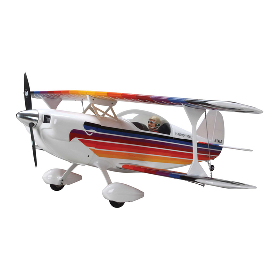
Scale: 28.7%
Length: 62.5 in [1585mm]
Wingspan: Top: 68.5 in [1740mm],
Bottom: 64.5 in [1640mm]
Combined Wing Area: 1436 sq in [92.6 dm
Weight: 16.5 - 18 lbs [6800 - 8160 g]
Wing Loading: 26 - 29 oz/sq ft [79 - 88 g/dm
Great Planes
®
Model Manufacturing Co. guarantees this kit to be free from defects in both material and workmanship at the date of
purchase. This warranty does not cover any component parts damaged by use or modification. In no case shall Great Planes' liability
exceed the original cost of the purchased kit. Further, Great Planes reserves the right to change or modify this warranty without notice.
In that Great Planes has no control over the final assembly or material used for final assembly, no liability shall be assumed nor
accepted for any damage resulting from the use by the user of the final user-assembled product. By the act of using the user-assembled
product, the user accepts all resulting liability.
If the buyer is not prepared to accept the liability associated with the use of this product, the buyer is advised to return this
kit immediately in new and unused condition to the place of purchase.
READ THROUGH THIS MANUAL BEFORE
STARTING CONSTRUCTION. IT CONTAINS
IMPORTANT WARNINGS AND INSTRUCTIONS
CONCERNING THE ASSEMBLY AND USE OF
THIS MODEL.
© Copyright 2003
INSTRUCTION MANUAL
2
]
2
]
WARRANTY
Radio: 4-channel, 8-9 servos
Engine: 1.6 - 2.2 cu in [26 - 35cc] two-stroke,
1.8 - 3.0 cu in [30 - 49cc] four-stroke,
2.0 - 3.2 cu in [32 - 52cc] gas
Champaign, Illinois
(217) 398-8970, Ext 5
airsupport@greatplanes.com
GPMZ0222 for GPMA1217 V1.0
Advertisement
Table of Contents

Related Manuals for GREAT PLANES Christen Eagle II


Summary of Contents for GREAT PLANES Christen Eagle II
-
Page 1: Instruction Manual
Further, Great Planes reserves the right to change or modify this warranty without notice. In that Great Planes has no control over the final assembly or material used for final assembly, no liability shall be assumed nor accepted for any damage resulting from the use by the user of the final user-assembled product. -
Page 2: Table Of Contents
For the latest technical updates or manual corrections to the Mount the Servos.............28 Great Planes Christen Eagle II ARF, visit the web site listed Mount the Tail Gear ............29 below and select the Great Planes Christen Eagle ARF. If there Assemble the Fuel Tank...........29... -
Page 3: Scale Competition
IMPORTANT SAFETY PRECAUTIONS end up with a well-built model that is straight and true. 1. Your Christen Eagle II should not be considered a toy, but If you have not flown this type of model before, we rather a sophisticated, working model that functions very recommend that you get the assistance of an experienced much like a full-size airplane. -
Page 4: Decisions You Must Make
This is a partial list of items required to finish the Great with the O.S. MAX FT-300 four-stroke twin. With this engine, Planes Christen Eagle II ARF that may require planning or the Eagle's vertical performance is virtually unlimited and it is decision making before starting to build. -
Page 5: Fuel Tank Setup
In addition to the items previously listed, following is a list of Following is a list of all the items required to convert the the rest of the items required to finish the Christen Eagle II stopper and fuel lines for use with gasoline: ARF. -
Page 6: Optional Supplies And Tools
Various small to medium-size C-clamps Sandpaper assortment Small, metal straightedge • The Christen Eagle II ARF is factory-covered with Top Fine-point felt-tip pen such as a Top Flite® Panel Line Flite MonoKote film. Following are the colors used and Pen (TOPQ2510) order numbers for 6' [1.8m] rolls. -
Page 7: Ordering Replacement Parts
ORDERING REPLACEMENT PARTS To order replacement parts for the Great Planes Christen Eagle II ARF, use the order numbers in the Replacement Parts List that follows. Replacement parts are available only as listed. Not all parts are available separately (an aileron cannot be purchased separately, but is only available with the wing kit). - Page 8 Kit Contents (Not Photographed) WASHERS: TAIL GEAR PARTS: PUSHRODS: Aluminum tail gear mount (4) 4-40 x 4-1/2" [115mm] pushrod (ailerons) (5) #4 lock washers (cowl ring) (13) #4 flat washers (5-cowl ring, 8-wing strut Tail gear wire (3) 4-40 x 5-3/4" [145mm] pushrod (elevators-2, mounting) 1-1/4"...
-
Page 9: Assemble The Wings
the wing and aileron. The best way is to glide the iron over the ASSEMBLE THE WINGS covering until the wrinkles disappear, then push down on the iron to bond the covering to the wood. If you come across a wrinkle that won’t go away, the balsa in that area may be Prepare the Wings bending inward. -
Page 10: Hinge The Ailerons
5. Cut the covering from the hole in the bottom of the 3. In order for the CA to get full penetration all the way into center section for the aileron servo wire. the hinge slots a strip of covering must be removed from each slot. -
Page 11: Join The Wings
Join the Wings Do the bottom wing first… 1. Round both ends of the 3/8" x 1-3/16" [10 x 30mm] hardwood wing dowels. 6. Adjust the aileron so there is a small gap between the trailing edge of the wing and the leading edge of the aileron—just enough to see light through or to slip a piece of paper through. - Page 12 3. Lay two or three paper towels on top of each other. Use 6. Tightly tape the wing together with several strips of scissors to cut them into smaller squares. These will come masking tape on the top and bottom. Use the small paper in handy throughout assembly.
-
Page 13: Hook Up The Ailerons
10. Prepare 1 oz. of 30-minute epoxy. The same as when 2. Connect a 12" [300mm] servo extension wire to the joining the bottom wing, thoroughly coat one side of the aileron servo. Slip a 1-1/2" [38mm] piece of heat shrink joiners and all mating surfaces of one side of the center tubing supplied with this kit over the connection, then panel and the adjoining outer panel with epoxy. -
Page 14: Assemble The Fuselage
8. IMPORTANT! The same as was done with the servo 10. Slide a silicone retainer over the clevis, then connect mounting screws, remove the screws holding the control the aileron to the servo with the pushrod. The clevis will be horn to the aileron and add a few drops of thin CA to harden adjusted and the nut will be tightened when setting up the the “threads”... - Page 15 bring it into alignment. If weight is not enough, remove the stab from the fuselage and lightly trim or sand the stab saddle as necessary until you can get the stab parallel with the wing. 5. Once the stab and wing align, center the trailing edge of the stab from side-to-side in the fuselage, taking accurate measurements.
- Page 16 in the photo. Swing the string over to the same position on the other end of the stab. Pivot the stab on the T-pin in the trailing edge and slide the tape along the string until the arrow aligns with both ends of the stab. 10.
-
Page 17: Mount The Engine
Mount the Engine 13. After the epoxy on the stab has hardened, slide the fin into position. Holding the rudder to the fin, make certain the top of the rudder aligns with the top of the fin and the bottom of the rudder aligns with the bottom of the fuselage. Place a weight over the aft end of the fuselage to hold it Also make sure the trailing edge of the fin is parallel with the down while mounting the engine (or skip ahead to page 28... -
Page 18: Engines 41Cc
1/4" [6.4mm] holes. Remove the template from the plywood (naphtha lighter fluid helps this process). 5. Using a Great Planes Dead Center Hole Locator or another suitable method, mark the location of the holes in the engine on the mount. -
Page 19: Fuji 50
5. Cut or drill clearance holes in the firewall for the heads of the bolts that hold the engine to the mount plate, then mount the plate to the firewall with four more 1/4-20 x 3/4" [19mm] bolts, washers and 1/4-20 blind nuts included with this kit. -
Page 20: Mount The Cowl
4. Cut the alignment pins to a length of 1/2" [13mm]. With the cowl ring fastened to the fuselage, push the alignment Note: The Christen Eagle II ARF features a unique cowl ring pins, rounded end first, into the cowl ring and F-1. - Page 21 8. Remove the prop and spinner. Look inside the cowl 10. Using the holes in the tabs as guides, drill 7/64" through the air inlets. Be certain you will be able to access the [2.8mm] holes through F-1. Remove the cowl ring. Enlarge five cowl mounting screws around the cowl ring with the the holes in F-1 only with a 9/64"...
- Page 22 14. Tack glue the cowl to the cowl ring by using the wood strip to apply eight to ten evenly spaced, 1/2" long “dabs” of epoxy to the cowl and cowl ring inside—the rest will be glued later. This is your chance to achieve perfect cowl alignment! View the model from all angles, making sure the cowl aligns with the spinner and there is adequate spacing between the cowl and spinner.
-
Page 23: Mount The Landing Gear
18. Mix up another thick batch of epoxy and MOUNT THE LANDING GEAR microballoons. Apply a small fillet all the way around the front of the cowl ring and the cowl. Reinstall the cowl, tighten the screws and stand the model up on end again. Allow the Fuelproof the Landing Gear Cutout epoxy to harden. - Page 24 How to “Bullet-Proof” Your Wheel Pants Here’s a way to add rigidity to the wheel pants and increase their service life. They still may not hold up to a crash, but they will survive the day-to-day rigors of bouncy landings and rough runways.
-
Page 25: Prepare The Landing Gear
7. Glue the plywood wheel pant doubler to the wheel pant brace inside each pant. The 3/16" [4.8mm] hole in the doubler must be centered over the 1/2" [13mm] hole in the pant (the E. Use your fingers or a wire to lift the epoxy-soaked wheel axles, cut to the correct length as shown on page 27, carbon fiber swatch from the plastic bag and place it inside could be used to align the holes). -
Page 26: Mount The Landing Gear Fairings
Perform the following four steps only if you will be mounting the optional flying wires on the wings. 4. Relieve the inside of the balsa cover where screw heads made their indentations. Set the cover aside. 5. Use RTV silicone or thin, double-sided foam mounting 3. -
Page 27: Mount The Wheel Pants
7. Trim the fairings where they meet the brackets. 1. Cut both 3/16" x 2" [4.8 x 50mm] wheel axles to a length of 1-3/4" [44mm]. File flat spots near the end of the axles, then use a 7/16" wrench and a 1/2" wrench to bolt the axles to the gear with 5/16-24 lock nuts. -
Page 28: Final Assembly
FINAL ASSEMBLY Mount the Servos Refer to these photos while mounting the servos and hooking up the pushrods. 4. Mark the two holes in both sides of the landing gear onto the pants. Note: Although there are molded-in indentations in both wheel pants for the landing gear, there is still room for adjustment so it is best to get it right by aligning the wheel pants in this way. -
Page 29: Mount The Tail Gear
securely tighten with a 1.5mm hex wrench. Add a few drops of oil to the wire where it enters the aluminum mount and on both sides of the tail wheel. 3. Enlarge the hole in the steering arm with a 3/32" [2.4mm] drill. - Page 30 brass tubing (not included). Cut the brass tubes to the correct length, then solder the barbs onto one end of the tubes. The long brass tube will be bent upward for the vent inside the tank. FRONT VIEW VENT LEFT SIDE RIGHT SIDE OF PLANE OF PLANE...
-
Page 31: Hook Up The Throttle
Refer to the following photos while hooking up the throttle. The setup shown is for the Fuji 50. 7. Insert the stopper and lines into the tank, but do not tighten the stopper. Use a felt-tip pen to write “top” on the top of the back of the tank so you won’t inadvertently install it upside-down. -
Page 32: Mount The Kill Switch (Gas Only)
the fueling line and the vent. A fuel line holder was made for 6. If using a glow engine, hook up the throttle using the the fueling line by drilling a 1/4" [6.4mm] hole through a 36" [910mm] wire pushrod. The threaded end of the pushrod basswood block (not included) and cutting a slot so the line is connected to a 2-56 ball link on the carburetor arm with a can be press-fit into the hole. -
Page 33: Finish The Cockpit
Finish the Cockpit Refer to this photo while finishing the cockpit. 1. Determine where and how you will be mounting the on/off ignition switch. Note: It is advisable to mount the switch on the top or side of the fuselage where it will be more readily accessible than it would be on the bottom of the fuselage where shown on the model in the photos. -
Page 34: Mount The Canopy
glue it inside the bottom of the pilot. Make a doubler for the screws out of plywood for the other side of the cockpit floor inside the fuselage. Drill the appropriate size holes for the screws, then glue and screw the pilot to the cockpit floor. Fabricate and install any other scale cockpit details desired. -
Page 35: Glue On The Belly Pan
5. Apply 30-minute epoxy to the bottom of the wing and Glue on the Belly Pan the belly pan where they contact each other—except for the front of the belly pan—this area will be glued down with medium CA. 6. Position the belly pan on the wing and bolt it down with the wing bolts. - Page 36 Do the top wing first. 3. Use #4 x 1/2" [13mm] screws to mount two each of the C3 and A3 metal brackets as shown. Note that the shorter surface of the C3 brackets contacts the wing. Also mount two B2 metal brackets for if installing flying wires. Note that the shorter part of the B2 brackets contacts the wing.
- Page 37 9. Use coarse sandpaper to smooth the molded-in parting line from both ends of both fiberglass wing struts where they contact the top and bottom wings. 6. Drill the holes in the bottom panel and mount the A1, C1 and B1 (for the optional flying wires) brackets as shown in the photo.
- Page 38 12. Use a fine-point felt-tip pen to mark a line behind the 17. Holding the top wing and left strut together, mark the strut brackets on both sides of the bottom wing 3/4" [19mm] holes in the top brackets onto the strut. It’s okay if pressure from the aileron hinge line.
-
Page 39: Mount The Flying Wires (Optional)
Mount the Flying Wires (Optional) 1. From clevis pin to clevis pin, measure the length of the wires supplied. The wires measuring 21-1/2" [545mm] are the front wing flying wires and go from the top wing down to the fuselage by the landing gear. The wires measuring 22-1/4" [565mm] are the rear wing flying wires and go from the bottom wing up to the top wing near the half-round cutout for the trailing edge over the cockpit. - Page 40 4. Mark the rear bracket on the other side of the fuselage and both front brackets on the middle of the stab leading edge the same way. 8. Turn the fuselage over. Connect the remaining four top tail wires to the brackets on the top of the stab. The same way the holes were marked in the bottom of the stab, mount four B4 brackets to the clevises on the ends of the top tail wires.
-
Page 41: Install The Aileron Extension Cord
2. Mount the on/off switch and charge jack. For our model a Great Planes Switch & Charge Jack Mounting Set (GPMM1000) was used so the battery pack could be easily charged and monitored from outside the fuselage without having to remove the wings. -
Page 42: Apply The Decals
1 on page 35 and below. Apply the Decals The recommended C.G. for the Christen Eagle II ARF is The decals may be cut from the sheet and applied directly 6-1/8" [156mm] back from the leading edge of the center to the model, or they may be applied “wet”... -
Page 43: Check The Control Directions
AMA number Use a Great Planes AccuThrow or a ruler to accurately on or inside your model. It is required at all AMA R/C club measure and set the control throw of each control surface as flying sites and AMA sanctioned flying events. -
Page 44: Charge The Batteries
We use a Top Flite Precision Magnetic Prop Balancer ™ operate engines. (TOPQ5700) in the workshop and keep a Great Planes Fingertip Prop Balancer (GPMQ5000) in our flight box. Use safety glasses when starting or running engines. Don’t forget to ream out your props to fit your engine before Do not run the engine in an area of loose gravel or sand;... -
Page 45: Ama Safety Code
Use a “chicken stick” or electric starter to start the engine. 3. I will perform my initial turn after takeoff away from the pit Do not use your fingers to flip the propeller. Make certain the or spectator areas and I will not thereafter fly over pit or glow plug clip or connector is secure so that it will not pop spectator areas, unless beyond my control. -
Page 46: Checklist
Section 6.0: RADIO REQUIREMENTS Control surfaces linkages are listed in order of preference: 6.1 All transmitters must be FCC type certified. 1. Cable system (pull-pull). A tiller bar is highly recommended along with necessary bracing. 6.2 FCC Technician or higher-class license required for 6 meter band operation only. -
Page 47: Flying
Top off the fuel, then check all fasteners FLYING and control linkages for peace of mind. The Christen Eagle II ARF is a great-flying model that flies Remember to takeoff into the wind. When ready, point the smoothly and predictably. It is, however, an aerobatic biplane... -
Page 48: Flight
One final note about flying your Christen Eagle. Have a goal Flight or flight plan in mind for every flight. The goal could be learning a new maneuver, perfecting known maneuvers, or For reassurance and to keep an eye on other traffic, it is a learning how the model behaves in certain conditions (such good idea to have an assistant on the flight line with you. -
Page 49: Engine Mount Templates
Fuji BT-50SA Engine Mounting Bolt Pattern 19/64" [7.6mm] Engine Bolt Holes Glow Engine Mounting Bolt Pattern... - Page 50 Align these lines with the lines on the firewall OTHER ITEMS AVAILABLE FROM GREAT PLANES Fuji BT-50SB Gasoline Engine A gasoline engine designed specifically for model airplanes, the BT-50SB has all of the performance features that Fuji engines are known for - with upgrades for effortless starting! The included Walbro carb has a butterfly choke valve that s easier to use than a slide-valve carb.
- Page 51 OTHER ITEMS AVAILABLE FROM GREAT PLANES Weight w/o Muffler: 32.6 oz Practical RPM Range: 1,800-10,000 BHP @ RPM: 3.7 @ 9,000 Stock # FUTJ85** 9CAF R148DF Servos (4) S3004 Tx NiCd 700mAh Rx NiCd 600mAh Band 50, 72 Modulation Stock #...
- Page 52 BUILDING NOTES Kit Purchased Date: _______________________ Date Construction Finished: _________________ Where Purchased:_________________________ Finished Weight: __________________________ Date Construction Started: __________________ Date of First Flight: ________________________ FLIGHT LOG...