GREAT PLANES Matt Chapman Cap 580 Instruction Manual
Hide thumbs
Also See for Matt Chapman Cap 580:
- Instruction manual (24 pages) ,
- Instruction manual (24 pages)
Table of Contents
Advertisement
Quick Links
Wingspan: 99.5 in [2525mm]
Wing Area: 1885 sq in [121.6 dm
Weight: 29-32 lb [13150-14520g]
Wing Loading: 35-39 oz/sq ft [107-119 g/dm
Length: 95 in [2415 mm]
Engine: 4.2-7.2 cu in [70-120cc]
Great Planes
®
Model Manufacturing Co. guarantees this kit to be free from defects in both material and workmanship at the date of
purchase. This warranty does not cover any component parts damaged by use or modification. In no case shall Great Planes' liability
exceed the original cost of the purchased kit. Further, Great Planes reserves the right to change or modify this warranty without notice.
In that Great Planes has no control over the final assembly or material used for final assembly, no liability shall be assumed nor
accepted for any damage resulting from the use by the user of the final user-assembled product. By the act of using the user-assembled
product, the user accepts all resulting liability.
If the buyer is not prepared to accept the liability associated with the use of this product, the buyer is advised to return this
kit immediately in new and unused condition to the place of purchase.
To make a warranty claim send the defective part or item to Hobby Services at the address below:
Include a letter stating your name, return shipping address, as much contact information as possible (daytime telephone number, fax
number, e-mail address), a detailed description of the problem and a photocopy of the purchase receipt. Upon receipt of the package
the problem will be evaluated as quickly as possible.
READ THROUGH THIS MANUAL BEFORE STARTING
CONSTRUCTION. IT CONTAINS IMPORTANT WARNINGS
AND INSTRUCTIONS CONCERNING THE ASSEMBLY
AND USE OF THIS MODEL.
© Copyright 2005
INSTRUCTION MANUAL
2
]
2
]
3002 N. Apollo Dr. Suite 1
Champaign IL 61822 USA
WARRANTY
Hobby Services
Champaign, Illinois
(217) 398-8970, Ext 5
airsupport@greatplanes.com
GPMZ0280 for GPMA1285 V1.0
Advertisement
Table of Contents

Related Manuals for GREAT PLANES Matt Chapman Cap 580


Summary of Contents for GREAT PLANES Matt Chapman Cap 580
-
Page 1: Instruction Manual
Further, Great Planes reserves the right to change or modify this warranty without notice. In that Great Planes has no control over the final assembly or material used for final assembly, no liability shall be assumed nor accepted for any damage resulting from the use by the user of the final user-assembled product. -
Page 2: Table Of Contents
Install the Rudder Servo(s)........13 the “Airplanes” link, then select the Great Planes 1/3-scale Install the Main Gear ..........14 Matt Chapman CAP 580 ARF. If there is new technical Mount the Engine............15 information or changes to this model a “tech notice” box will Install the Throttle Servo..........15... -
Page 3: Safety Precautions
If you would like photos of the full-size Great Planes 1/3- professionally designed and tested, and the engine range scale Matt Chapman CAP 580, or if you would like to study carefully selected for great performance. We strongly the photos to add more scale details, photo packs are... -
Page 4: Engine Recommendations
CA applicator tips (HCAR3780) The recommended engine size range for the Great Planes 1/3- CA debonder (GPMR6039) scale Matt Chapman CAP 580 is 4.2-7.2 cu in [80-120cc]. The Epoxy brushes (6, GPMR8060) DA100 provided fantastic power with unlimited vertical and the Mixing sticks (50, GPMR8055) weight balanced nicely. -
Page 5: Important Building Notes
LE = Leading Edge TE = Trailing Edge • The Great Planes 1/3-scale Matt Chapman CAP 580 ARF LG = Landing Gear is factory-covered with Top Flite MonoKote film. Should Ply = Plywood repairs ever be required, MonoKote can be patched with "... -
Page 6: Kit Contents
KIT CONTENTS Kit Contents (Photographed) 1 Cowl 8 Instrument Panel 2 Fuselage 9 Stab and Elevators 3 Canopy/Hatch 10 Stab Tubes 4 Aluminum Spinner 11 Rudder 5 Main Gear 12 Wings and Ailerons 6 Wheels 13 Wing Tube 7 Wheel Pants Kit Contents (Not Photographed) Brass Quick Connect Body (2) #4 Lock Washer (14) -
Page 7: Ordering Replacement Parts
To locate a hobby dealer, visit the Great Planes web site at www.greatplanes.com . Choose “Where to Buy” from the menu on the left side of the page. Follow the instructions provided on the page to locate a U.S., Canadian or International dealer. If a hobby shop is not available, replacement parts may also be ordered from Tower Hobbies at www.towerhobbies.com , or by... -
Page 8: Assemble The Stab
ASSEMBLE THE STAB Attach the Elevators 3. Place a drop of oil on the pivot point of each of the hinges. 1. Cut the covering from the five holes for the hinge points in the trailing edge of one of the stab halves and the leading edge of the elevator. -
Page 9: Prepare The Servo Arms
Head Cap Screw [SHCS] brass stand off and 4-40 lock nut. Prepare the Servo Arms Note: The number goes toward the servo arm. 5. Attach the ball links to the five other single-sided Note: The included aluminum servo arms are designed with servo arms. - Page 10 4. Drill a 9/64" [3.6 mm] hole through the elevator centered on the pivot washer. 8. Assemble the control horn parts as shown. 5. Cut the 4" [100mm] control horn bolt to a length of 9. Screw the reverse threaded end of the 2-1/2" 2-1/4"...
-
Page 11: Assemble The Wing
12. Remove the stock servo arm from the servo. Plug the servo into the receiver and turn the radio on. 13. Place the appropriate servo arm insert on the servo. The inserts have letters stamped on the bottom of them (A=Airtronics/JR, F=Futaba, H=Hitec). 3. -
Page 12: Assemble The Fuse
ASSEMBLE THE FUSE Install the Tail Gear 5. Mount the control horns and servo arms following the same steps used with the stab. 1. Grind flat spots on the tail gear wire for the set screws. Assemble the tail gear as shown in the photo with threadlocker. 2. -
Page 13: Attach The Rudder
Attach the Rudder Install the Rudder Servo(s) RUDDER SERVO OPTIONS: The large size of the rudder on the Giant CAP 580 requires a lot of servo torque. Our testing shows that less than 300 ounce inches of servo power results in rudder “blow back” during certain maneuvers. -
Page 14: Install The Main Gear
Install the Main Gear 1. Attach the axle to the main gear with the nylon lock nut. 2. Install a wheel collar with a 6-32 x 1/4" [6mm] SHCS, the wheel and the other wheel collar also with a 6-32 x 1/4" [6mm] SHCS. 3. -
Page 15: Mount The Engine
6. Mount the landing gear to the fuse with threadlocker, 3. Mount the engine to the firewall with 1/4-20 x 2-1/2" four 8-32 x 3/4" [19mm] SHCS, four #8 flat washers and four [64mm] bolts and the correct number of aluminum spacers #8 lock washers. - Page 16 1. Drill a 3/16" [4.8mm] hole through the firewall and 5. Cut a 1" [25mm] threaded section from one of the second former aligned with the throttle arm on engine. 2-56 x 4" [102mm] pushrods. Attach the nylon clevis to the white plastic pushrod using the threaded section.
-
Page 17: Install The Servo Operated Kill Switch
[2.4mm] wheel collars and two 1/2" [13mm] pieces of fuel line. Kill Switch (Not Included) For safety, Great Planes recommends the installation of both a servo operated kill switch and a manual kill switch. A Great Planes kill switch (GPMG2150, not included) is used in all of our gasoline-powered aircraft. -
Page 18: Assemble And Install The Fuel Tank
Assemble and Install the Fuel Tank 5. Mount the tank to the tank tray with two #64 rubber bands. 1. Assemble the stopper, brass tubes and steel stopper end plates as shown. 2. Solder the brass barbs to the ends of the brass tubes. Note: Get the tubes just hot enough for the solder to flow. -
Page 19: Final Assembly
so you can get it to fit over the engine. If you are using the DA100, only a small hole for the front of the left muffler and slots for the muffler tubes need to be cut. 6. Working one at a time, repeat steps 4 and 5 to install 3 bolts on each side of the cowl. -
Page 20: Finish The Radio Installation
Check the C.G. There are two wing locations on the plane. The reason for this is so that a range of engines can be used without the need for adding large amounts of weight to balance. 1. First, determine which wing mounting location you will use. -
Page 21: Attach The Canopy
Attach the Canopy Apply the Decals 1. Use scissors or a sharp hobby knife to cut the decals from the sheet. 2. Be certain the model is clean and free from oily fingerprints and dust. Prepare a dishpan or small bucket with a mixture of liquid dish soap and warm water—about one teaspoon of soap per gallon of water. -
Page 22: Set The Control Throws
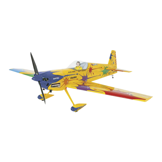
Great Planes 1/3-scale 3. If the tail drops, the model is “tail heavy” and the battery Matt Chapman CAP 580 ARF flies, you would like to pack and/or receiver must be shifted forward or weight must change the throws to suit your taste, that is fine. -
Page 23: Balance The Model Laterally
Follow the battery charging instructions that came with your added by using Great Planes (GPMQ4485) “stick-on” lead. A radio control system to charge the batteries. You should good place to add stick-on nose weight is to the firewall or the always charge your transmitter and receiver batteries the engine box itself (don’t attach weight to the cowl—it is not... -
Page 24: Engine Safety Precautions
ENGINE SAFETY PRECAUTIONS AMA SAFETY CODE ( EXCERPTS Read and abide by the following excerpts from the Academy Failure to follow these safety precautions may result of Model Aeronautics Safety Code. For the complete Safety in severe injury to yourself and others. Code refer to Model Aviation magazine, the AMA web site or the Code that came with your AMA license. - Page 25 This will also prevent accidental Since the Great Planes 1/3-scale Matt Chapman CAP 580 starting of the engine. This switch shall be readily available qualifies as a “giant scale”...
-
Page 26: Checklist
2. Check the C.G. according to the measurements • Generally, it is recommended that no attempt should be provided in the manual. made to fly a radio controlled model aircraft with a gasoline 3. Be certain the battery and receiver are securely engine in which the model aircraft weight would exceed 12 mounted in the fuse. -
Page 27: Takeoff
Take it easy with the Great Planes 1/3-scale Matt Chapman CAUTION (THIS APPLIES TO ALL R/C AIRPLANES): If, CAP 580 ARF for the first few flights, gradually getting while flying, you notice an alarming or unusual sound such as acquainted with it as you gain confidence. Adjust the trims to a low-pitched “buzz,”... - Page 28 BUILDING NOTES Kit Purchased Date: _______________________ Date Construction Finished: _________________ Where Purchased:_________________________ Finished Weight: __________________________ Date Construction Started: __________________ Date of First Flight: ________________________ FLIGHT LOG...
Need help?
Do you have a question about the Matt Chapman Cap 580 and is the answer not in the manual?
Questions and answers