GREAT PLANES Matt Chapman Cap 580 Instruction Manual
Hide thumbs
Also See for Matt Chapman Cap 580:
- Instruction manual (28 pages) ,
- Instruction manual (24 pages)
Table of Contents
Advertisement
Quick Links
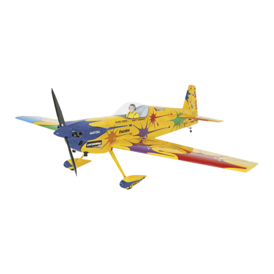
Wingspan: 55.5 in [1410mm]
Wing Area: 562 sq in [36 dm
Weight: 6.75-7.5 lb [3060-3400 g]
Wing Loading: 28-30 oz/sq ft [85-92 g/dm
Length: 52.5 in [1335mm]
Radio: 4-channel, five servos
Engine: .46-.61 cu in [7.5-10cc] two-stroke,
.52-.70 cu in [8.5-11.5cc] four-stroke
Great Planes
®
Model Manufacturing Co. guarantees this kit to be free from defects in both material and workmanship at the date of
purchase. This warranty does not cover any component parts damaged by use or modification. In no case shall Great Planes' liability
exceed the original cost of the purchased kit. Further, Great Planes reserves the right to change or modify this warranty without notice.
In that Great Planes has no control over the final assembly or material used for final assembly, no liability shall be assumed nor
accepted for any damage resulting from the use by the user of the final user-assembled product. By the act of using the user-assembled
product, the user accepts all resulting liability.
If the buyer is not prepared to accept the liability associated with the use of this product, the buyer is advised to return this
kit immediately in new and unused condition to the place of purchase.
To make a warranty claim send the defective part or item to Hobby Services at the address below:
Include a letter stating your name, return shipping address, as much contact information as possible (daytime telephone number, fax
number, e-mail address), a detailed description of the problem and a photocopy of the purchase receipt. Upon receipt of the package
the problem will be evaluated as quickly as possible.
READ THROUGH THIS MANUAL BEFORE STARTING
CONSTRUCTION. IT CONTAINS IMPORTANT WARNINGS
AND INSTRUCTIONS CONCERNING THE ASSEMBLY
AND USE OF THIS MODEL.
© Copyright 2004
INSTRUCTION MANUAL
2
]
2
]
3002 N. Apollo Dr. Suite 1
Champaign IL 61822 USA
WARRANTY
Hobby Services
Champaign, Illinois
(217) 398-8970, Ext 5
airsupport@greatplanes.com
GPMZ0250 for GPMA1280 V1.0
Advertisement
Table of Contents

Related Manuals for GREAT PLANES Matt Chapman Cap 580


Summary of Contents for GREAT PLANES Matt Chapman Cap 580
-
Page 1: Instruction Manual
Further, Great Planes reserves the right to change or modify this warranty without notice. In that Great Planes has no control over the final assembly or material used for final assembly, no liability shall be assumed nor accepted for any damage resulting from the use by the user of the final user-assembled product. -
Page 2: Table Of Contents
For the latest technical updates or manual corrections to the TABLE OF CONTENTS CAP 580 .40 -.70 ARF visit the Great Planes web site at www.greatplanes.com. Open the “Airplanes” link, then select INTRODUCTION ..............2 the CAP 580 ARF. If there is new technical information or AMA ...................2... -
Page 3: Additional Items Required
9. WARNING: The cowl and wheel pants included in this kit is the “short list” of the most important items required to build are made of fiberglass, the fibers of which may cause eye, the CAP 580 .40 - .70 ARF. Great Planes Pro ™ CA and skin and respiratory tract irritation. -
Page 4: Important Building Notes
• The CAP 580 is factory-covered with Top Flite ® MonoKote ® Hobbico Duster ™ Compressed Air (HCAR5500) film. Should repairs ever be required, MonoKote can be Masking Tape (TOPR8018) patched with additional MonoKote purchased separately. Threadlocker Thread Locking Cement (GPMR6060) MonoKote is packaged in six-foot rolls, but some hobby Denatured Alcohol (for epoxy clean up) shops also sell it by the foot. -
Page 5: Kit Contents
If any parts are missing or are not of acceptable quality, or if you need assistance with assembly, contact Product Support. When reporting defective or missing parts, use the part names exactly as they are written in the Kit Contents list. Great Planes Product Support: 3002 N Apollo Drive, Suite 1 Champaign, IL 61822 Telephone: (217) 398-8970, ext. -
Page 6: Ordering Replacement Parts
ORDERING REPLACEMENT PARTS Replacement parts for the Great Planes Cap 580 .40 - .70 ARF are available using the order numbers in the Replacement Parts List that follows. The fastest, most economical service can be provided by your hobby dealer or mail-order company. -
Page 7: Preparations
PREPARATIONS 1. If you have not done so already, remove the major parts of the kit from the box and inspect for damage. If any parts 1" are damaged or missing, contact Product Support at the [25mm] address or telephone number listed in the “Kit Inspection” section on page 5. -
Page 8: Install The Aileron Servos And Pushrods
Install the Aileron Servos and Pushrods 1. For the servo installation a Y-harness connector is required and is used to allow the aileron servos to plug into one slot in your receiver.You may have a computer radio that allows you to plug the servos into separate slots and mix them together through the radio transmitter. -
Page 9: Join The Wing
Join the Wing 3-3/8" [86mm] 3. Apply 30-minute epoxy to all sides of the wing joiner, the joiner pocket in both wing panels and the root rib of each wing panel. Insert the wing joiner, push the wing panels together and hold them in place with masking tape. Before the glue hardens, set the wing flat on your bench and measure the dihedral. -
Page 10: Assemble The Fuselage
ASSEMBLE THE FUSELAGE Install the Stab, Elevators and Rudder HOW TO CUT COVERING FROM BALSA 1. Test fit the stab into the opening in the back of the Use a soldering iron to cut the covering from the stab. The fuselage. - Page 11 4. Cut the covering from the center section of the stab, being careful not to cut into the wood structure. Use the same 9. Bend the wire 90 degrees. Once the wire is bent, cut technique used for cutting the covering for the wing bolt plate. the wire to extend 1-1/2"...
-
Page 12: Install The Landing Gear And Wheel Pants
3. File a flat spot on the end of the axles. (A high speed rotary tool works well for this also). 14. Mount the tail wheel onto the tail wheel wire. Secure 4. Install an aluminum spacer (it looks just like a wheel collar without the hole for the set screw) followed by a wheel it to the wire with a 3/32"... - Page 13 5. Position the engine in the mount so the distance from the front of the firewall to the front of the thrust washer measures 5-3/16" [132mm]. Mark the location of the engine on the mount. The Great Planes ® Dead Center ™...
-
Page 14: Install The Cowl
Install the Cowl 12. Locate a .074 x 17.5” [445mm] pushrod wire. Cut the threaded end from the wire. Insert the wire into the plastic tube you installed for the throttle. Install a brass screw lock connector into the throttle arm, locking it to the arm with a nylon retainer. Insert this wire into the screw lock connector and the plastic tube you installed for the throttle. -
Page 15: Install The Radio System
1/16" [1.6mm] drill bit, drilling through the elevator. Secure the 4. For this step you will find that a helper will be an asset. control horn to the aileron with two 2-56 x 5/8” [16mm] Position the cowl onto the fuselage, aligning the paint lines machine screws and the nylon mounting plate. - Page 16 with the hole in the servo arm. On that mark make a 90 degree bend. From the bend measure an additional 3/16" [4.8mm] and then cut off the excess pushrod wire. Install a nylon Faslink to the wire and servo arm. 11.
-
Page 17: Final Touches
4. Use a piece of soft balsa or something similar to Use a Great Planes AccuThrow (or a ruler) to accurately squeegee remaining water from under the decal. Apply the measure and set the control throw of each control surface as rest of the decals the same way. -
Page 18: Balance The Model (C.g.)
2. With the wing attached to the fuselage, all parts of the model installed (ready to fly) and an empty fuel tank, place the model upside-down on a Great Planes CG Machine, or More than any other factor, the C.G. (balance point) can lift it upside-down at the balance point you marked. -
Page 19: Balance The Model Laterally
™ name, address, telephone number and AMA number on or (TOPQ5700) in the workshop and keep a Great Planes inside your model. It is required at all AMA R/C club flying sites Fingertip Prop Balancer (GPMQ5000) in our flight box. -
Page 20: Engine Safety Precautions
General ENGINE SAFETY PRECAUTIONS 1. I will not fly my model aircraft in sanctioned events, air Failure to follow these safety precautions may result shows, or model flying demonstrations until it has been in severe injury to yourself and others. proven to be airworthy by having been previously, successfully flight tested. -
Page 21: Flying
4. Extend your receiver antenna and make sure it has a CAUTION (THIS APPLIES TO ALL R/C AIRPLANES): If, strain relief inside the fuselage to keep tension off the while flying, you notice an alarming or unusual sound solder joint inside the receiver. such as a low-pitched “buzz,”... -
Page 22: Flight
Level the attitude when the model reaches the runway threshold, modulating the throttle as necessary to maintain ALSO AVAILABLE FROM GREAT PLANES Futaba ® 4YF 4-Channel FM Radio FUTJ40** First in affordability and features. -
Page 23: Engine Mount Template
Stroke: 0.787 in (20mm) Recommended Props: 9.5x6, 10x6, 11x5 Output: 1.48 bhp @ 15,500 rpm Give your Great Planes Matt Chapman CAP 580 extra punch for impressive, airshow-worthy climbs, loops, and snaps! The G-51 mounts in the same space as a .40... - Page 24 BUILDING NOTES Kit Purchased Date: _______________________ Date Construction Finished: _________________ Where Purchased:_________________________ Finished Weight: __________________________ Date Construction Started: __________________ Date of First Flight: ________________________ FLIGHT LOG...
Need help?
Do you have a question about the Matt Chapman Cap 580 and is the answer not in the manual?
Questions and answers