Advertisement
Quick Links
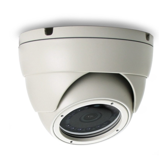
IR Dome Camera User Manual
The product image shown above may differ from the actual product.
Please use this camera with a DVR which supports HD video recording.
Please read the instructions thoroughly before using the product.
IR Dome Camera User Manual
The product image shown above may differ from the actual product.
Please use this camera with a DVR which supports HD video recording.
Please read the instructions thoroughly before using the product.
680Z
d104a_V1.3
680Z
d104a_V1.3
Advertisement

Related Manuals for Avtech IR Dome Camera


Summary of Contents for Avtech IR Dome Camera
- Page 1 680Z IR Dome Camera User Manual The product image shown above may differ from the actual product. Please use this camera with a DVR which supports HD video recording. Please read the instructions thoroughly before using the product. d104a_V1.3 680Z IR Dome Camera User Manual The product image shown above may differ from the actual product.
- Page 3 IMPORTANT SAFEGUARD CAUTION RISK OF ELECTRIC SHOCK CAUTION: To reduce the risk of electric shock, do not expose this apparatus to rain or moisture. Only operate this apparatus from the type of power source indicated on the label. The company shall not be liable for any damages arising out of any improper use, even if we have been advised of the possibility of such damages. The lightning flash with arrowhead symbol, within an equilateral triangle, is intended to alert the user to the presence of uninsulated “dangerous voltage”...
-
Page 5: Table Of Contents
TABLE OF CONTENTS FEATURES PACKAGE CONTENT DIMENSIONS* SPECIFICATIONS* INSTALLATION CONNECTION CAMERA PARAMETERS TABLE OF CONTENTS FEATURES PACKAGE CONTENT DIMENSIONS* SPECIFICATIONS* INSTALLATION CONNECTION CAMERA PARAMETERS... -
Page 7: Features
4. Day and night 24-hour surveillance with IR effective distance up to 15 meters 5. IP66 for weather-proof application 6. Camera parameters adjustable when used with HD CCTV DVR PACKAGE CONTENT IR dome camera User manual Camera case Wrench Screws & wall plugs FEATURES 1. -
Page 8: Dimensions
DIMENSIONS* *Dimensional Tolerance: ± 5mm DIMENSIONS* *Dimensional Tolerance: ± 5mm... -
Page 9: Specifications
SPECIFICATIONS* Pick-up Element 1/ 2.7” CMOS image sensor Number of Pixels 1930(H) x 1088(V) Video Frame Rate 1080P@30fps / 1080P@25fps Min. Illumination 0.1 Lux / F1.8, 0 Lux (IR LED ON) S/N Ratio More than 48dB (AGC OFF) Shutter Speed 1/30 (1/25) sec ~ 1/720000 (1/600000) sec Lens f3.6mm / F1.8... -
Page 10: Installation
INSTALLATION Step1: Disassemble the camera case into three parts as illustrated in Figure 1. Base Part 1 Part 2 Figure 1 Step2: Locate where you want to install this camera (wall or ceiling), and drill holes on the wall or ceiling for securing the bracket and routing the cables (if necessary). - Page 11 Step3: Attach the bracket to the wall (or ceiling), and make sure the cables are routed and arranged properly in the bracket, as shown in Figure 2. Step4: Secure the bracket to the wall (or ceiling), as shown in Figure 4. Figure 2 Figure 3 Step3: Attach the bracket to the wall (or ceiling), and make sure the cables are routed and arranged...
- Page 12 Step5: Slightly adjust the camera lens to where it’s supposed to face, and replace Part 1 and Part 2 back, as shown in Figure 4 and Figure 5. Step6: Hold the camera lens and Part 1, and rotate only Part 2 clockwise, as shown in Figure 5. Figure 4 Figure 5 Step7: Power on your camera, and check the viewing angle on the PC.
-
Page 13: Connection
CONNECTION 1. DC12V Input Terminal Connect the power terminal of the camera to a DC 12V regulated power supply. Note: Please use the correct power adaptor, DC12V (regulated), to operate this unit. The power tolerance of this unit is DC12V ± 10%. Over maximum DC 12V power input will damage this unit. -
Page 14: Camera Parameters
CAMERA PARAMETERS This camera series has its own configuration menu, and either of the two methods below is available to access the menu based on the camera model you have. Note: The methods below are available only when the camera is used with our brand’s HD CCTV DVR. - Page 15 ADVANCED CONFIG CAMERA DETECTION MENU SETUP ALERT NETWORK DISPLAY RECORD DEVICES F.W. 1007 DCCS DEVICE XXXXX NOTIFY CONNECTION When the camera menu is entered, you’ll see the keys on the bottom right corner to move between and change those configurations. ...
- Page 16 MENU DESCRIPTION DAY / MODE Use the external light sensor we added in the NIGHT camera to detect the surrounding light condition and switch to color or B/W mode. If you’re not satisfying with the mode switch time, you can go to D TO N / N TO D to manually adjust the sensitivity.
- Page 17 MENU DESCRIPTION Set the sensitivity for the day & night mode from night DAY / N TO D 1 ~ 63 to day. NIGHT The higher the value, the more sensitivity the mode is switched when the light condition is changed. Note: This function is not available when AUTO and COLOR is selected.
- Page 18 MENU DESCRIPTION MODE (PUSH) It’s used for the environment surrounded largely by a particular color, such as blue, causing color confusion. Aim the camera to a white place, and select (PUSH) to memory this white. Then, aim the camera to where it’s supposed to face. HOLD It’s used to force the camera memorizing the current white balance setting and remain the same...
- Page 19 MENU DESCRIPTION BRIGHT 0 ~ 255 Set the level of brightness to adjust the brightness of the image. (automatic exposure) The more the value, the brighter the image. SHUTTER AUTO Automatically adjust the shutter speed for exposure based on the current environment. 1/25 Manually choose the shutter speed you need for exposure.
- Page 20 MENU DESCRIPTION FLICKER OFF / 50HZ / Enable this function to fix the flicker situation. 60HZ (automatic exposure) 1 ~ 5 Set the level of Auto Gain Control to detect and enhance the image signals when the light condition is poor. The higher the value, the stronger the signals will be enhanced, and the more noise the image will get.
- Page 21 MENU DESCRIPTION SPECIAL PRIVACY Extend / narrow the current area from the left side. ZONE Extend / narrow the current area from the right side. Extend / narrow the current area from the top. Extend / narrow the current area from the bottom. MOTION* MOTION Enable (ON) / disable (OFF) motion detection.
- Page 22 MENU DESCRIPTION SPECIAL HLC (high light compensation) is used to suppress strong backlight for clearer images. A grey mask will be covered on the source of the strong light. Choose ON and click (ENTER) to select the areas for this function. The screen will be divided into 16 areas.
- Page 23 MENU DESCRIPTION EFFECT COLOR 0 ~ 255 Set the level of color saturation. GAIN The more the value, the more saturated the color will be, but the more noise the image will get. COLOR HUE 0 ~ 71 Set the level of hue. SHARPNESS 0 ~ 255 Set the level of sharpness to enhance the clarity...
- Page 24 MENU DESCRIPTION EFFECT MIRROR OFF / ON Enable to turn the images horizontally based on your installation situation when necessary. FLIP OFF / ON Enable to flip the image 180° when necessary. SYSTEM CAMERA ID 0 ~ 255 Set the camera ID. ID DISP.
Need help?
Do you have a question about the IR Dome Camera and is the answer not in the manual?
Questions and answers