Table of Contents
Advertisement
Quick Links
Federal Communications Commission (FCC) Statement
This equipment has been tested and found to comply with the limits for a Class B digital
device, pursuant to Part 15 of FCC Rules. These limits are designed to provide reasonable
protection against harmful interference in a residential installation. This equipment
generates, uses and can radiate radio frequency energy and, if not installed and used in
accordance with instructions contained in this manual, may cause harmful interference
to radio and television communications. However, there is no guarantee that interference
will not occur in a particular installation.
If this equipment does cause harmful interference to radio or television reception, which
can be determined by turning the equipment off and on, the user is encouraged to try to
correct the interference by one or more of the following measures:
-
REORIENT OR RELOCATE THE RECEIVING ANTENNA
-
INCREASE THE SEPARATION BETWEEN THE EQUIPMENT AND THE RECEIVER
-
CONNECT THE EQUIPMENT INTO AN OUTLET ON A CIRCUIT DIFFERENT FROM
THAT OF THE RECEIVER
-
CONSULT THE DEALER OR AN EXPERIENCED AUDIO/TELEVISION TECHNICIAN
NOTE: Connecting this device to peripheral devices that do not comply with Class B
requirements, or using an unshielded peripheral data cable, could also result in
harmful interference to radio or television reception.
The user is cautioned that any changes or modifications not expressly approved
by the party responsible for compliance could void the user's authority to operate
this equipment.
To ensure that the use of this product does not contribute to interference, it is
necessary to use shielded I/O cables.
Copyright
This manual is copyrighted with all rights reserved. No portion of this manual may be
copied or reproduced by any means.
While every precaution has been taken in the preparation of this manual, no responsibility
for errors or omissions is assumed. Neither is any liability assumed for damages resulting
from the use of the information contained herein.
Trademarks
All brand names, logos and registered trademarks mentioned are property of their
respective owners.
Electronic Emission Notices
SAPPHIRE PURE PERFORMANCE II
1
Advertisement
Table of Contents

Related Manuals for Sapphire Audio PP-I7RS400 PURE PERFORMANCE II


Summary of Contents for Sapphire Audio PP-I7RS400 PURE PERFORMANCE II
-
Page 1: Electronic Emission Notices
Electronic Emission Notices Federal Communications Commission (FCC) Statement This equipment has been tested and found to comply with the limits for a Class B digital device, pursuant to Part 15 of FCC Rules. These limits are designed to provide reasonable protection against harmful interference in a residential installation. -
Page 2: Table Of Contents
TABLE OF CONTENTS HARDWARE CONFIGURATION ..............4 Key Features ....................4 MOTHERBOARD LAYOUT ................7 REAR PANEL ....................8 AUDIO CONFIGURATION ................10 SPEAKER CONFIGURATION ................ 10 Method 1: 2/4/6 Channel audio output on back panel only ....10 Method 2: Using S-Bracket connectors ..........12 CONNECTORS ..................... - Page 3 SLOTS ......................27 CPU INSTALLATION ..................28 MEMORY CONFIGURATIONS ..............32 DDR DIMM Sockets Location ..............32 Install DDR DIMMs ................. 32 Memory Configurations ................. 33 BIOS SETUP ....................34 Starting Setup ..................34 Main Menu ....................35 Standard CMOS Features ..............36 Advanced BIOS Features ...............
-
Page 4: Hardware Configuration
HARDWARE CONFIGURATION Key Features Chipset • ATI® RS400+SB400 Chipset. Processor • Supports Intel® Celeron® , Pentium® 4 processors in the LGA775 -pin package (with 0.8V~1.6V voltage). • Supports 64-bit PSB (Processor System Bus) frequency of 400MHz/ 533MHz/800MHz (100MHz/133MHz/200MHz bus clock). VRM 10.0 (Voltage Regulator Modules) on Board •... -
Page 5: Onboard Vga
Onboard I/O • Onboard two PCI fast IDE ports supporting up to 4 ATA, ATA2 , Ultra ATA33/66/100/133 IDE HDDs, CD-ROMs, ZIP drives and LS-120 drives as boot drive. • One ECP/EPP parallel port. • One 16550 Compatible UART serial ports.(Via a header) •... -
Page 6: Expansion Slots
PCI Express Graphics Interface • One 16-lane (x16 port) PCI Express port intended for Graphics Attach, Fully compliant to the PCI Express Base Specification revision 1.0a. • A base PCI Express frequency of 2.5GB/s only. • PCI Express supports and Enhanced Addressing Mechanism. PCI Express x1 Port •... -
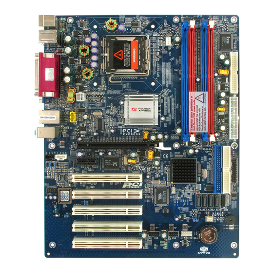
Page 7: Motherboard Layout
MOTHERBOARD LAYOUT The following diagrams show the relative positions of the jumpers, connectors, major components and memory banks on the Sapphire motherboard. LGA775 Socket NOTE Be sure to check the cable orientation in order to match the colored strip to the pin1 end of the connector. -
Page 8: Rear Panel
REAR PANEL The back panel provides the following connectors: PS/2 Mouse Connector The Sapphire motherboard provides a standard PS/2 mouse mini DIN ® connector for attaching a PS/2 mouse.You can plug a PS/2 mouse directly ® ® into this connector. PS/2 Keyboard Connector The Sapphire motherboard provides a standard PS/2 keyboard mini DIN... -
Page 9: Spdif Connector
VIA VT6307 IEEE 1394 Connector The Sapphire motherboard provides a IEEE 1394 Connector and allows you to connect a IEEE 1394 device directly to the connector. TV Out Connector connect a 15-pin The Sapphire motherboard provides a Video out port to analog video monitor. -
Page 10: Audio Configuration
AUDIO CONFIGURATION After installing the audio driver, you can select 2/4/6 channel surround audio output in software utility and then connect surround speakers to appropriate audio ports. There are two ways to obtain 2/4/6 channel audio output: 2/4/6 channel audio output of back panel only. All surround speakers connect to audio connector. - Page 11 In the audio software, please double click the “AC97 Audio configuration” icon from the window tray on the bottom right to launch the Audio Wizard. The “AC97 Audio Configuration” will appear. Click on the Speaker Configuration tab to select the audio mode. A.
-
Page 12: Method 2: Using S-Bracket Connectors
Method 2: Using S-BRACKET connectors: S-Bracket (The S-Bracket is showed in page 15) is an optional accessory. It gives access to analog and digital audio output by integrating both SPDIF and analog LINE OUT connectors. To use the S-Bracket, you should select correct setting in the software utility. - Page 13 6-Channel Analog Audio Output Back Panel S-Bracket (Front channels) Description: Connect two speakers to back panel Line Out connector and four speakers to both Line Out connectors of S-Bracket, or six speakers to the connector of S-Bracket. If you want to use Line In and MIC function at the same time, please click the Rear Speaker Out and Center/Subwoofer Speaker Out buttons.
-
Page 14: Connectors
CONNECTORS The Sapphire motherboard provides connectors to connect to FDD, IDE HDD, USB Ports and CPU/System FAN etc. Floppy Disk Drive Connector - CN3 The Sapphire motherboard provides a standard floppy disk drive connector that supports 360K, 720K, 1.2M, 1.44M and 2.88M floppy disk types. IDE Connectors - CN1, CN2 The Sapphire motherboard has a 32-bit Enhanced PCI IDE and Ultra DMA 33/ 66/100/133 controller that provides PIO mode 0~4, Bus Master, and Ultra DMA... -
Page 15: Six Channel Audio Output Connector - J19
Six Channel Audio Output Connector - J19 The Sapphire motherboard provides six channel output(FL/FR,RL/RR,CEN/ LEF) connector, that allows you to use the 6 channel audio output features at the same time. SIGNAL DESCRIPTION SOUT-L Audio left surrounding output SOUT-R Audio right surrounding output Ground Ground CET-OUT... -
Page 16: Tv Out Header - J3
TV Out Header - J3 The Sapphire motherboard provides TV Out header. J3 - Pin Definition Assignment COMP/B TV Out cable PP-I7RS400 User’s Manual... -
Page 17: Ieee1394 Connector - J23
IEEE 1394 Connector - J23 The Sapphire motherboard provides a 1394 pin header that allow you to connect IEEE 1394 ports. J23 - Pin Definition SIGNAL TPA+ TPA- Ground Ground TPB+ TPB- Cable power Cable power Key (no pin) Ground IEEE 1394 Cable (optional) SAPPHIRE PURE PERFORMANCE II... -
Page 18: Chassis Alarm Lead - Jp12
Chassis Alarm Lead: JP12(optional) This lead is for a chassis designed with intrusion detection feature.this requires an external detection mechanism such as a chassis intrusion sensor or microswitch.When you remove any chassis component,the sensor triggers and sends a high-level signal to this lead to record a chassis intrusion event. JP12 JP12 - Pin Definition Assignment... -
Page 19: Fan Power Connectors - Cpufan1, Sysfan1
Fan Power Headers - CPUFAN1, SYSFAN1 The CPUFAN1 (processor fan), SYSFAN1 (system fan) support system cooling fan with +12V. It supports three-pin head connector. SYSFAN1 Power LEDs - D55, D54 The green LED lights when the system is in the power-on state. The red LED lights whenever AC mains power is attached, irrespective of whether the system is power-on or power-off or standby mode. -
Page 20: Cd-In Header - J18
CD-IN Header - J18 This header allows for connection from the CD-ROM Drive. AUX-IN Header - J20 This header allows for connection from the Audio Device. J18 - Pin Definition Assignment CD-L CD-R J20 - Pin Definition Assignment AUX-L AUX-R PP-I7RS400 User’s Manual... -
Page 21: Front Panel Audio Header - Fp-S1
Front Panel Audio Header - FP-S1 This Sapphire motherboard supports front panel microphone and speaker out ports. If your computer case has these ports,connect them to FP-S1. FP-S1 FP-S1 - Pin Definition Assignment POWER Front Audio(R) Rear Audio(R) Reserved Key(No pin) Front Audio(L) Rear Audio(L) Note:... -
Page 22: Usb Headers - Fp-U1, Fp-U2
USB Headers - FP-U1, FP-U2 This Sapphire motherboard has eight USB ports. Some computer cases have a special module that mounts USB ports at the front of the case. If you have this kind of case, use auxiliary USB connector FP-U1, FP-U2 to connect the front mounted ports to the Sapphire mainboard. -
Page 23: Front Panel Header - Fp1
Front Panel Header - FP1 The Sapphire motherboard provides a front panel connection to the front panel switches and LEDs. FP1 is compliant with the Front Panel I/O Connectivity Design Guide. KEYLOCK SPEAKER IRRX IRTX RESET PWR_SW PW_LED- HDD_LED- PW_LED+ HDD_LED+ SAPPHIRE PURE PERFORMANCE II... -
Page 24: Serial Ata Hard Disk Connectors - Sata1/Sata2/Sata3/Sata4
Serial ATA Hard Disk Connectors - SATA1/SATA2/SATA3/SATA4 The Sapphire motherboard has four SATA connectors. Each supports generation SATA data rates of 150 MB/s. Both connectors are fully compliant with Serial ATA 1.0 specifications. Each SATA connector can connect to one hard disk device. Please refer to SATA Raid setup (Page 38) for detail software installation procedure. - Page 25 Serial ATA Cable Connect one end of the SATA cable to the Sapphire motherboard and connect the other end to the SATA Hard Disk. Please do not fold the serial ATA cable in a 90-degree angle, which will cause the loss of data during the transmission. Serial ATA Hard Disk Devices Power Cable (optional) SAPPHIRE PURE PERFORMANCE II...
-
Page 26: Jumper Setting
JUMPER SETTING The Sapphire motherboard provides jumpers enabling configuration of the hardware. Clear CMOS Jumper - JP9 If you want to clear the system configuration, use the JP9(Clear CMOS Jumper) to clear data. Selection 1-2* Normal* CMOS Clear Onboard AC97 Sound Select - JP2 Function 1-2* AC97 Sound Enable*... -
Page 27: Slots
SLOTS The Sapphire motherboard provides one PCI-E x16 slot, one PCI-E x1 slot and five 32-bit PCI bus slots. PCI-E x16 Slot PCI-E x1 Slot PCI Slots PCI Express x16 Graphics Interface • One 16-lane (x16 port) PCI Express port intended for external graphics. -
Page 28: Cpu Installation
CPU INSTALLATION Please refer to the following steps to install the CPU. 1.Please turn off the power and unplug the power cord before installing the CPU. Use index finger and thumb to raise the metal lever so it is separated from the bottom steel shell grip hook. - Page 29 4.Use index finger and thumb to press down the metal lever.The cap will be pushed up by the CPU. This may also be done by removing the lid beforehand. 5.Press the metal lever so it is secured in the bottom steel shell grip hook.
- Page 30 6. It is recommended that the CPU heatsink should be approved by Intel Corporation. Choose the orientation of the thermal solution for optimal wire routing to the fan header on the Sapphire motherboard. Position the thermal solution over the processor. Ensure the fan wiring is positioned to prevent wire pinching between the heatsink and the processor, or between the heatsink clip and the socket.
- Page 31 9. Gently rotate the cap clockwise 1/4 turn to fasten the heatsink onto the Sapphire motherboard. 10. Lastly, attach the fan wire connector to the 4 pin fan header connector Sapphire motherboard labeled CPU FAN. SAPPHIRE PURE PERFORMANCE II...
-
Page 32: Memory Configurations
MEMORY CONFIGURATIONS 1.DDR DIMM Sockets Location Please refer to the following figure for the location of the DDR DIMM Sockets. 2.Install DDR DIMMs Please follow the below mentioned steps to install DDR DIMMs. 1. Hold the DDR DIMM module by the edges and remove it from its antistatic package. -
Page 33: Memory Configurations
3. Memory Configurations Please refer to the following recommended memory configurations in Table1. Recommended Memory Configurations Mode/(DIMM Type) Case Sockets - DDR1 DDR2 DDR3 DDR4 Single-channel/ Populated ---- ---- ---- ---- Populated ---- ---- ---- ---- Populated ---- ---- ---- ---- Populated Populated Populated ----... -
Page 34: Bios Setup
BIOS SETUP About the Setup Utility The computer uses the latest Award BIOS with support for Windows Plug and Play. The CMOS chip on the motherboard contains the ROM setup instructions for configuring the motherboard BIOS. The BIOS (Basic Input and Output System) Setup Utility displays the system’s configuration status and provides you with options to set system parameters. -
Page 35: Main Menu
Main Menu Once you enter the Award BIOS CMOS Setup Utility, the Main Menu will appear on the screen. It allows you to select from various setup functions and two exit choices. Use the arrow keys to select among the items and press <Enter> to accept and enter the sub- menu. -
Page 36: Standard Cmos Features
Load Fail-Safe The BIOS defaults have been set by Sapphire and represent Defaults settings which provide the minimum requirements for your system to operate. Load Optimized The chipset defaults are settings which provide for maximum Defaults system performance. Sapphire has assigned these values to provide optimized performance. -
Page 37: Advanced Bios Features
Date The date format is <day-of-the-week> <month> <day> <year>. Time The time format is <hour> <minute> <second> displayed in 24-hour system. Primary and Your computer has two IDE channels: primary and secondary. Secondary And each channel can be installed with one or two devices Master, Slave (master and slave). -
Page 38: Set Supervisor/User Password
Set Supervisor/User Password When this function is selected, the following message appears at the center of the screen to assist you in creating a password. ENTER PASSWORD Type the password, up to eight characters, and press <Enter>. The password typed now will clear any previously entered password from CMOS memory. You will be asked to confirm the password. -
Page 39: Bios Update Procedure
BIOS Update Procedure A program AWDFLASH.EXE is included in the utility diskette or CD (X:\Utility\ AWDFLASH.EXE). The user is recommended to follow the procedure below to update the flash BIOS. (X: your CD driver letter). 1. Create a DOS-bootable floppy diskette. Copy the new BIOS file (just obtained or downloaded) and the utility program AWDFLASH.EXE to the diskette. -
Page 40: Sata Raid Setup
SATA RAID SETUP Creating and deleting RAID sets is a function found in the RAID utility. During bootup, the following message will appear, pausing for a few seconds to allow the user to enter the RAID utility: Press Ctrl+S or F4 to enter RAID utility An easy-to-use screen will appear with the following choices: Create RAID Set Delete RAID Set Rebuild RAID Set Resolve Conflicts Below this will be a list of drives currently installed on the system. -
Page 41: Resolving Conflict
Resolving Conflicts When a RAID set is created, the metadata is written to the disk includes drive connection information (Primary Channel, Secondary Channel). If, after a disk failure, the replacement disk was previously part of a RAID set (or used in another system), it may have conflicting metadata, specifically in reference to the drive connection information. -
Page 42: Appendix
APPENDIX Note to User: The bundled driver CD attached an Auto-Run feature for all the drivers that the Sapphire motherboard needs. Please select the drivers that you want to install and click the button on the installation panel. PP-I7RS400 User’s Manual... - Page 43 SAPPHIRE PURE PERFORMANCE II...
- Page 44 PP-I7RS400 User’s Manual FC1117A8...
Need help?
Do you have a question about the PP-I7RS400 PURE PERFORMANCE II and is the answer not in the manual?
Questions and answers