Table of Contents
Advertisement
Advertisement
Table of Contents

Related Manuals for Sapphire Audio Pure Platinum Z77


Summary of Contents for Sapphire Audio Pure Platinum Z77
- Page 1 User’s Manual Sapphire Pure Platinum Z77/Z77K Intel Z77 / LGA1155 Mainboard TRADEMARK All products and company names are trademarks or registered trademarks of their respective holders. These specifications are subject to change without notice. Manual Revision 1.0 March 23, 2012...
- Page 2 Federal Communications Commission (FCC) Statement This device has been tested and found to comply with the limits for a Class B digital device, pursuant to Part 15 of FCC Rules. These limits are designed to provide reasonable protection against harmful interference in a residential installation.
-
Page 3: Table Of Contents
Table of Contents Chapter 1 Introduction .............. 1 1-1 Mainboard Specifications ............1 1-2 Package Contents ..............4 1-3 Mainboard Layout ..............5 Chapter 2 Installation .............. 10 2-1 Before You Begin ..............10 2-2 Installing the I/O Shield ............10 2-3 Securing to the Chassis ............ - Page 4 3-3 Main Menu ................27 3-4 Performance Menu ..............28 CPU Configuration ..............29 Memory Configuration .............. 31 Voltage Configuration ............... 33 3-5 Advanced Menu ............... 34 ACPI Settings ................35 S5 RTC Wake Settings ............. 36 CPU Configuration ..............37 CPU Information ...............
-
Page 5: Chapter 1 Introduction
Chapter 1 Introduction 1‐1 Mainboard Specifications ® Supports Intel Core i7/i5/i3 series processor in LGA1155 package ® Supports Intel Turbo Boost technology, Hyper-Threading technology Chipset ® Intel Z77 chipset Graphics ® Intel HD graphic Four independent displays supporting concurrent display of either two combination of HDMI, DVI, VGA and Display Port Port Supported resolution... -
Page 6: Onboard Audio
SATA Ports Two SATA3 ports with 6Gb/s data transfer rate and four SATA2 ports with 3Gb/s data transfer rate ® Support Intel Rapid Start Technology with RAID 0, 1, 10 and 5 ® Supports Intel Smart Response Technology ... - Page 7 2 x USB 3.0 ports 6 Audio jacks Internal I/O Connectors 1 x 24-pin ATX power connector 1 x 8-pin ATX 12V power connector 1 x 4-pin power connector 2 x SATA3 connectors ...
-
Page 8: Package Contents
Form Factor ATX form factor of 305mm x 245mm Operating systems: Supports Windows Vista and Windows 7 1‐2 Package Contents Your Sapphire mainboard comes with the following accessories. 1. Mainboard 2. I/O Shield 3. Quick Installation Guide 4. Driver DVD 5. -
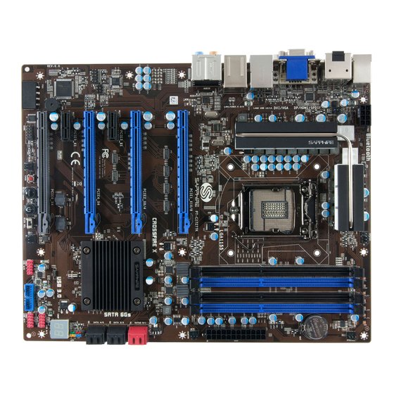
Page 9: Mainboard Layout
1‐3 Mainboard Layout The following figure shows the location of components on the mainboard. See following page for description. Note: Picture is for reference only, actual board may be slightly different. ~ 5 ~ ... - Page 10 Item Component description 1 CPU Socket 1155 2 Intel Z77 Chip 3 DDR3 DIMM Slots 1‐4 4 PCI‐E 3.0 x16 Slots *3 5 PCI‐E 2.0 x16 Slots *1 6 PCI‐E 2.0 x1 Slot *2 7 24‐Pin ATX Power Connector 8 8‐pin ATX_12V Power Connector 9 4‐pin Power Connector 10 SATA3 Connectors *2 11 SATA2 Connectors *4 12 Front Panel Header 13 USB 2.0 Header *6 14 USB 3.0 Header *2 15 Power Button 16 Reset Button 17 Clear CMOS Button 18 ...
- Page 11 I/O Back Panel The I/O back panel for this mainboard is shown below. When installing the mainboard into the computer case, use the bundled I/O shield to protect this back panel. PS/2 Keyboard/Mouse Port This connector is used for a keyboard or mouse. You can plug a PS/2 keyboard or mouse directly into this connector.
- Page 12 digital interconnection between the computer and its display device. Connect a monitor that supports DVI-D connection to this port. The DVI-D port does not support analogue VGA monitors using a passive DVI to VGA adapter. Dual Display Configurations: This mainboard provides four ports for video output: VGA, DVI-D, HDMI and Display port.
-
Page 13: Audio Ports
11. Audio ports This mainboard provides 2, 6 or 8 channel audio. It is easy to differentiate between the audio functions by referring to the color of the jacks. Ports 2 channel 6 channel 8 channel Blue Line-In Line-In Line-In Lime Line-Out... -
Page 14: Chapter 2 Installation
Chapter 2 Installation 2‐1 Before You Begin Please take note of all precautions before you install anything on to the mainboard or change any of the mainboard settings. Turn off the power to your system and discharge your body’s static electric charge by touching a grounded surface—for example, the metal surface of the power supply—before performing any hardware procedure. -
Page 15: Installing The Cpu And Cooler
2‐4 Installing the CPU and Cooler Follow the steps below to install the CPU & cooler correctly. 1. Open the socket lever by pushing the lever down and away from the socket. Remove the protective socket cover from the socket. Do not touch the socket contacts. Do not touch the socket contacts to avoid damaging. -
Page 16: Installing System Memory
2‐5 Installing System Memory This mainboard has four 240-pin DIMM sockets for DDR3 memory. These slots support 1GB, 2GB, 4GB and 8GB DDR3 DIMMs up to max. 32GB. Make sure that you install memory modules of the same type and density in the different channel DIMM slots for Dual-Channel mode. -
Page 17: Installing Expansion Cards
2‐6 Installing Expansion Cards The mainboard provides three PCI Express 3.0 x16 slots, one PCI Express 2.0 x16 slot and two PCI Express 2.0 x1 slots. Note: The PCI-E Gen3 function will be available when using PCIe 3.0 compliant devices. PCIE1_X16/8 PCI‐E3.0 x16 slot (with x16/x8 link, Blue) PCIE2_X8/4 PCI‐E3.0 x16 slot (with x8/x4 link, Blue) ... - Page 18 Installing a PCI Express card: Place the card in an available PCI Express slot and press down on the card until it is completely seated in the slot. If the card is not seated properly, it could cause a short across the pins. Secure the card’s metal bracket to the back panel of the chassis with a screw.
-
Page 19: Connecting Cables
2‐7 Connecting Cables This section takes you through all the necessary connections on the mainboard. Connecting Power Supply Cables 24-pin ATX Power PW1 is the main power supply connector. Make sure that the power supply cable pins are properly aligned with the connector on the mainboard. Firmly plug the power supply cable into the connector and make sure it is secure. -
Page 20: Connecting Serial Ata (Sata) Cables
Connecting Serial ATA (SATA) Cables SATA cables support the Serial ATA protocol. Each cable can be used to connect one SATA drive to the mainboard. The S1 to S3 connectors are controlled by the Intel Z77 chip and support RAID 0, 1, 10, 5 functions. Red coloured connector (S1) works at speeds of up to 6G/s. -
Page 21: Connecting To The Internal Headers And Connectors
Connecting to the Internal Headers and Connectors Front Panel Header The front panel header on this motherboard is used to connect the front panel switches and LEDs. PWR_LED Attach the front panel power LED cable to these two pins of the connector. The Power LED indicates the system’s status. System Status Power LED indicates The LED is on... -
Page 22: Usb2.0 Headers
USB2.0 Headers This mainboard contains four (4) USB 2.0 ports that are exposed on the rear panel of the chassis. This mainboard also contains three 10-pin onboard header connectors that can be used to connect to six (6) external USB 2.0 devices. Refer to the following steps: 1. -
Page 23: Cfpa Header
CFPA Header This header allows you to connect the front panel audio. The audio connector supports HD audio standard. S/PDIF Header This header is used to connect S/PDIF (Sony & Philips Digital Interconnect Format) interface for digital audio transmission. Serial Port Header The Serial port header (COM1) can provide one serial port via an optional COM port cable. -
Page 24: Fan Headers
Fan Headers There are six fan headers (CPUFAN, SYSFAN, SYSFAN1, PWRFAN, CHAFAN, AUXFAN) on the motherboard. Three of these fans (CPUFAN, PWRFAN, CHAFAN) can be speed detected/controlled and displayed in the Hardware Health Configuration section of the CMOS Setup. The fans are automatically turned off after the system enters S3, S4 or S5 mode. -
Page 25: Diagnostics Led
2‐8 Diagnostics LED This mainboard provides a two-digit POST code to show why the system may be failing to boot. It is useful during a troubleshooting situation. This Debug LED will also display the current CPU temperature after the system has fully booted into the operating system. -
Page 26: Onboard Buttons
2‐10 Onboard Buttons These onboard buttons include Clear CMOS, RESET and POWER, which allow you to easily clear the CMOS, reset the system and turn on/off the system. Clear CMOS Button The mainboard uses the CMOS RAM to store some of the system configuration. The CMOS can be cleared by pressing the Clear CMOS button. -
Page 27: Dual Bios Switch
2‐11 Dual BIOS Switch Recover BIOS: This mainboard includes dual onboard BIOS, (Primary and Secondary BIOS), When the primary BIOS is corrupted or has failed, the system will automatically switch to secondary BIOS to boot to ensure normal system operation. Please refer to the following steps: 1. -
Page 28: Flash Bios
Flash BIOS: If the primary (secondary) BIOS is corrupted or outdated, you can use the USB pen drive or AMI Windows flash utility to do flashing BIOS process to recover the primary (secondary) BIOS. Flash primary BIOS: Make sure the BIOS select switch is at “P”... -
Page 29: Chapter 3 Configuring The Bios
Chapter 3 Configuring the BIOS This chapter provides information on the BIOS Setup program and allows you to configure the system for optimum use. 3‐1 Select Boot Device Select Boot Device Menu allows you to set the first boot device without entering BIOS Setup. - Page 30 upon the bottom of the display during Power On Self Test (POST). Press F1 to continue, DEL to enter Setup. Pressing Del takes you to the BIOS Setup Utility. Note1: It is strongly recommended that you do not change the default BIOS settings.
-
Page 31: Main Menu
3‐3 Main Menu When entering the BIOS Setup Utility, the main menu screen appears. This main menu includes the system overview and displays the basic system configuration, such as BIOS information, memory size and system date/time. Set the Date. Use BIOS Information Tab to switch BIOS Vendor American Megatrends between Data Core Version ... -
Page 32: Performance Menu
3‐4 Performance Menu The Performance menu allows you to specify your settings for CPU, memory, voltage control and overclocking. Press <Enter> to display the configuration options. Graphics Core Ratio Limit 23 Graphics Core Ratio Limit Graphics Voltage (1/256) 0 CPU Configuration Memory Configuration Voltage Configuration 1.152 100.00 1.512 3511 1.000 ... -
Page 33: Cpu Configuration
CPU Configuration Host Clock Override Host Clock Override (1/100 MHz) 10000 Enhanced Intel SpeedStep Technology [Enabled] CPU C3 Report [Enabled] CPU C6 Report [Enabled] CPU C7 Report [Enabled] Turbo Mode [Enabled] Internal PLL Overvoltage [Disabled] Adjust By All Core [Disabled] 1 Core Ratio Limit 39 2 Core Ratio Limit 39 3 Core Ratio Limit 37 4 Core Ratio Limit 37 1.152 100.00 1.512 3511 1.000 16384 12.140 1600 Host Clock Override(1/100 MHz) Selects the value for Host Clock Override. - Page 34 Turbo Mode Enables the processor cores to run faster than marked frequency in specification condition. Options: Enabled, Disabled. Internal PLL Overvoltage This feature is only support on K-SKU CPUs for overclocking, enable this function will cause the S3 resume failure. Options: Enabled, Disabled.
-
Page 35: Memory Configuration
Memory Configuration The selection of Memory SPD Type [Standard] Performance Memory Memory Base Clock [133MHz] Profiles which impacts Memory Frequency [1600MHz (133*12)] memory sizing CAS# Latency (tCL) 9 behavior. RAS# to CAS# Delay(tRCD) 9 Row Precharge Time(tRP) 9 RAS# Active Time(tRAS) 28 Write Recovery Time(tWR) 12 Row Refresh Cycle Time(tRFC) 128 Write to Read Delay(tWTR) 6 Active to Active Delay(tRRD) 5 Read CAS# Precharge(tRTP) 6 Four Active Windows Delay(tFAW) 24 NMode Support [Auto] 1.152 100.00 1.512 ... - Page 36 CAS# Latency (tCL) Set the CAS latency time. Options: Auto(9), 5 ~ 15. RAS# to CAS# Delay (tRCD) Set the RAS to CAS Delay time for Read/Write commands to the same bank. Options: Auto(9), 4 ~ 15. Row Precharge Time (tRP) Set the Row Precharge time.
-
Page 37: Voltage Configuration
Voltage Configuration Voltage Configuration CPU Loadline CPU Loadline [100%] CPU Vcore [Auto] DIMM Voltage [Auto] CPU VSA/VTT [Auto] CPU PLL VCore [Auto] PCH VCore [Auto] 1.152 100.00 1.512 3511 1.000 16384 12.140 1600 CPU Loadline Loadline Control function is a safety measure to protect the CPU. Options: 100%, 75%, 50%, 25%, Disabled. -
Page 38: Advanced Menu
Allows you to adjust the Intel PCH VCore Voltage. Options: Auto, 1.050V ~2.625V in 0.025 increments. 3‐5 Advanced Menu The Advanced menu items allow you to change the settings for the CPU, USB and other system devices. Press <Enter> to display the configuration options. Legacy OpROM Support Enables or disable ... -
Page 39: Acpi Settings
ACPI Settings Enables or Disables ACPI Settings system ability to Hibernate (OS/S4 Enable Hibernation [Enabled] Sleep Sate). This ACPI Sleep State [S3 (Suspend to RAM)] option may be not S3 Video Repost [Disabled] effective with some ERP Function [Disabled] Restore AC Power Loss [Power Off] 1.152 100.00 1.512 3511 1.000 16384 12.140 1600 Enable Hibernation Enables system ability to Hibernate (OS/S4 Sleep Sate). This option may be not effective with some OS. -
Page 40: S5 Rtc Wake Settings
Restore on AC Power Loss Enables your computer to automatically restart or return to its last operating status after power returns from a power failure. Options: Power off, Power on, Last State. S5 RTC Wake Settings Enable or Disable Wake systems with Fixed Time [Disbled] System wake on ... -
Page 41: Cpu Configuration
CPU Configuration CPU Configuration CPU Configuration Intel(R) Core(TM) i7‐3770K CPU @ 3.50GHz CPU Information Hyper‐threading [Enabled] Active Processor Cores [All] Limit CPUID Maximum [Disabled] Execute Disable Bit [Enabled] Intel Virtualization Technology [Enabled] 1.152 100.00 1.512 3511 1.000 16384 12.140 1600 Hyper-threading This item enables the Intel Hyper-Threading technology. Options: Enabled, Disabled. -
Page 42: Cpu Information
Options: Enabled, Disabled. CPU Information Displays the CPU related information. CPU Information Intel(R) Core(TM) i7‐3770K CPU @ 3.50GHz CPU Signature 306a9 Microcode Patch 8 Max CPU Speed 3500 MHz Min CPU Speed 1600 MHz CPU Speed 3500 MHz Processor Cores 4 Intel HT Technology Supported Intel VT‐X Technology Supported Intel VT‐X Technology Not Supported 64‐bit Supported L1 Data Cache 32 KB x 4 L1 Code Cache 32 KB x 4 ... -
Page 43: Sata Configuration
SATA Configuration SATA Controller(s) [Enabled] Enable or disable SATA Mode Selection [AHCI] SATA Device. Serial ATA Port 0 [Enabled] Hot Plug [Disable] Serial ATA Port 1 [Enabled] Hot Plug [Disable] Serial ATA Port 2 [Enabled] Hot Plug [Disable] Serial ATA Port 3 [Enabled] Hot Plug [Disable] Serial ATA Port 4 [Enabled] Hot Plug [Disable] Serial ATA Port 5 [Enabled] Hot Plug [Disable] 1.152 100.00 1.512 3511 1.000 ... -
Page 44: Usb Configuration
USB Configuration Enable/Disable USB Configuration USB3.0 (XHCI) Controller Support. USB Devices: 1 Keyboard, 1 Mouse USB3.0 Support [Enabled] XHCI Hand‐off [Enabled] EHCI Hand‐off [Enabled] USB Hardware delays and time‐outs: USB transfer time‐out [1 sec] Device reset time‐out [10 sec] Device power‐up delay [Auto] 1.152 100.00 1.512 3511 1.000 16384 12.140 1600 USB3.0 Support Enables USB3.0 (XHCI) controller support. Options: Enabled, Disabled. -
Page 45: Super Io Configuration
Device power-up delay Maximum time the device will take before it properly reports itself to the Host controller. ‘Auto’ uses default values; for a Root port it is 100ms, for a Hub port the delay is taken from Hub descriptor. Options: Auto, Manual. -
Page 46: H/W Monitor
H/W Monitor PC Health Status Smart Fan Configuration CPU Temperature : +22 C VREG Temperature : +45 C System Temperature : +29 C CPU Fan Speed : 1567 RPM Power Fan Speed : N/A Chassis Fan Speed : N/A VCC3V : +3.200 V CPU VCore : +1.152 V CPU VTT : +0.992 V PCH : +1.032 V VDIMM : +1.512 V VCC : +4.960 V +12V : +12.032 V VSB3V : +3.328 V VBAT : +3.392 V 1.152 100.00 1.512 ... -
Page 47: Smart Fan Configuration
Smart Fan Configuration SmartFan Configuration CPU Fan Type [PWM FAN (4 pin)] CPU Fan Mode Setting [SmartFan] Temperature Limit of Highest 060 Temperature Limit of Lowest 030 Fan Highest setting 100 Fan Lowest setting 050 Power Fan Mode Setting [SmartFan] Temperature Limit of Highest 060 Temperature Limit of Lowest 030 Fan Highest setting 100 Fan Lowest setting 050 Chassis Fan Mode Setting [SmartFan] Temperature Limit of Highest 060 Temperature Limit of Lowest 030 Fan Highest setting 100 Fan Lowest setting CPU Fan Type Allows you to select the CPU Fan type. Options: PWM FAN (4 pin), Linear FAN (3 pin) CPU Fan Mode Setting This item controls the speed of the various fans on the motherboard. -
Page 48: Onboard Device Configuration
Onboard Device Configuration Onboard LAN1 (Realtek) [Enabled] Control the Onboard LAN1 Onboard LAN2 (Killer) [Enabled] Azaila HD Audio [Enabled] C80P Show CPU Temperature [Enabled] PS2 Port Type [Keyboard] 1.152 100.00 1.512 3511 1.000 16384 12.140 1600 Onboard LAN1 (Realtek) Enables the onboard Giga Lan 1 function by Realtek for LAN. Options: Enabled, Disabled Onboard LAN2 (Killer) (Optional) Enables the onboard Giga Lan 2 function by Killer for LAN. -
Page 49: Chipset Menu
3‐6 Chipset Menu The chipset menu items allow you to change the advanced chipset settings. Press <Enter> to display the sub-menu. Select which of Primary Display [Auto] IGFX/PEG/PCI Internal Graphics [Auto] Graphics device Aperture Size [256MB] should be Primary DVMT Pre‐Allocated [64M] Display or select SG for Switchable Gfx. DVMT Total Gfx Mem [256M] ... - Page 50 320MB, 352MB, 384MB, 416MB, 448MB, 480MB, 512MB, 1024MB. DVMT Total Gfx Mem Select DVMT 5.0 total graphics memory size used by the internal graphics device. Options: 128MB, 256MB, MAX. ~ 46 ~ ...
-
Page 51: Boot Menu
3‐7 Boot Menu The Boot menu is used to configure the boot settings and the boot priority. Number of seconds to Boot Configuration wait for setup Setup Prompt Timeout 1 activation key. Bootup NumLock State [On] 65535(0xFFFF) means indefinite waiting. Boot Option Priorities Boot Option #1 [P2: ST3250318AS] Boot Option #2 [P4: PIONEER DVD‐RW...] CD/DVD ROM Drive BBS Priorities Hard Drive BBS Priorities ... -
Page 52: Security Menu
3‐8 Security Menu The Security menu allows you to change the system security settings. Password Description Set setup Administrator Password. If ONLY the Administrator’s password is set, then this only limits access to Setup and is only asked for when entering Setup. If ONLY the User’s password is set, then this is a power on password and must be entered to boot or enter setup. In Setup the user will have Administrator rights. The password must be in the following range: Minimum length 3 Maximum length 20 Administrator Password User Password 1.152 100.00 1.512 3511 1.000 16384 12.140 1600 Administrator Password This function is used to set, change or delete the Administrator password. -
Page 53: Save & Exit Menu
3‐9 Save & Exit Menu The Save & Exit menu allows you to load the optimal default values for BIOS, and save or discard your changes to the BIOS items. Save Changes and Reset Reset the system Discard Changes and Reset after saving the changes. Restore Defaults Save as User Defaults Restore User Defaults Boot Override P2: DVDRW SATA 24X24X12X P4: WDC WD5000AAKX‐001CA0 ... - Page 54 Boot Override This group of functions includes a list, each of them corresponding to one device within the boot order. Select a drive to immediately boot that device regardless of the current boot order. S_BIOS Flash Utility This utility allows you to update the system BIOS in embedded BIOS. Please refer to "4-4 S_BIOS Flash Utility"...
-
Page 55: Chapter 4 Driver Installation
Chapter 4 Driver Installation After the operating system has been installed, you need to install drivers for this mainboard. The support DVD that came with the motherboard contains necessary drivers and useful utilities that enhance the motherboard features. 4‐1 Driver Install Insert the bundled driver DVD into your optical drive and the main menu... -
Page 56: Trixx Utility
4‐2 TRIXX Utility TRIXX is a simple and easy-to-use utility that allows users to adjust system settings for overclocking in a Windows environment. The TRIXX utility includes three configurations for frequency, voltage and hardware monitoring. To install TRIXX Utility, run it from the Sapphire Utility page from the bundled DVD. -
Page 57: Hardware Monitor Gadget
4‐3 Hardware monitor gadget This Hardware monitor gadget directly appears in windows screen after TriXX installation is completed. It can be used to help keep track of temperatures of CPU, System and fan speed of CPU, System and voltages of CPU, System. ... -
Page 58: S_Bios Flash Utility
4‐4 S_BIOS Flash Utility This mainboard provides a BIOS update tool. The S_BIOS allows you to update the system BIOS without having to enter MS-DOS or Windows environment. Embedded in the BIOS, the S_BIOS is simple and easy-to-use utility to flash BIOS. - Page 59 Setp3: To Update BIOS form Drive, select the BIOS update file and press <OK> to start update. If the BIOS file stored in USB device, please must first insert USB device before turning on the system and make sure the BIOS update file matches your mainboard model.
- Page 60 Setp4: The update BIOS processing screen appears. Setp5: The BIOS update is completed. Please press any key to restart the system. ~ 56 ~ ...
- Page 61 Setp6: Save BIOS to Drive, allows you to save the current BIOS file. If the BIOS file stored in USB device, please must first insert USB device before turning on the system. Setp7: To Save BIOS to Drive, Select the stored location and press <OK> to start saving BIOS file.
- Page 62 Setp8: After saving BIOS file is completed. Select <Ese> to return “Exit” tab of BIOS setup. ~ 58 ~ ...
-
Page 63: Chapter 5 Post Code
Chapter 5 POST Code This chapter provides the Aptio POST Codes List for the mainboard during the BIOS pre-boot process. The POST Codes are displayed on the Debug LED readout located directly onboard the mainboard. Please refer to following “boot phases”, which may apply to various status code &... - Page 64 05 OEM initialization before microcode loading 06 Microcode loading 07 AP initialization after microcode loading 08 North Bridge initialization after microcode loading 09 South Bridge initialization after microcode loading 0A OEM initialization after microcode loading 0B Cache initialization SEC Error Codes 0C – 0D Reserved for future AMI SEC error codes 0E Microcode not found 0F Microcode not loaded PEI Phase Status Code Description Progress Codes 10 PEI Core is started 11 Pre‐memory CPU initialization is started 12– 14 Pre‐memory CPU initialization (CPU module specific) 15 Pre‐memory North Bridge initialization is started 16 Pre‐Memory North Bridge initialization (North Bridge module specific) 17 Pre‐Memory North Bridge initialization (North Bridge module specific) ...
- Page 65 3C Post‐Memory South Bridge initialization (South Bridge module specific) 3D Post‐Memory South Bridge initialization (South Bridge module specific) 3E Post‐Memory South Bridge initialization (South Bridge module specific) 3F‐4E OEM post memory initialization codes 4F DXE IPL is started PEI Error Codes 50 Memory initialization error. Invalid memory type or incompatible memory speed 51 Memory initialization error. SPD reading has failed 52 Memory initialization error. Invalid memory size or memory modules do not match. 53 Memory initialization error. No usable memory detected 54 Unspecified memory initialization error. 55 Memory not installed 56 Invalid CPU type or Speed 57 CPU mismatch 58 CPU self test failed or possible CPU cache error 59 CPU micro‐code is not found or micro‐code update is failed 5A Internal CPU error 5B reset PPI is not available 5C‐5F ...
- Page 66 DXE Phase Status Code Description 60 DXE Core is started 61 NVRAM initialization 62 Installation of the South Bridge Runtime Services 63 CPU DXE initialization is started 64 CPU DXE initialization (CPU module specific) 65 CPU DXE initialization (CPU module specific) 66 CPU DXE initialization (CPU module specific) 67 CPU DXE initialization (CPU module specific) 68 PCI host bridge initialization 69 North Bridge DXE initialization is started 6A North Bridge DXE SMM initialization is started 6B North Bridge DXE initialization (North Bridge module specific) 6C North Bridge DXE initialization (North Bridge module specific) 6D North Bridge DXE initialization (North Bridge module specific) 6E North Bridge DXE initialization (North Bridge module specific) 6F North Bridge DXE initialization (North Bridge module specific) 70 South Bridge DXE initialization is started 71 ...
- Page 67 A1 IDE Reset A2 IDE Detect A3 IDE Enable A4 SCSI initialization is started A5 SCSI Reset A6 SCSI Detect A7 SCSI Enable A8 Setup Verifying Password A9 Start of Setup AA Reserved for ASL (see ASL Status Codes section below) AB Setup Input Wait AC Reserved for ASL (see ASL Status Codes section below) AD Ready To Boot event AE Legacy Boot event AF Exit Boot Services event B0 Runtime Set Virtual Address MAP Begin B1 Runtime Set Virtual Address MAP End B2 Legacy Option ROM Initialization B3 System Reset ...
Need help?
Do you have a question about the Pure Platinum Z77 and is the answer not in the manual?
Questions and answers