Table of Contents
Advertisement
User's Manual
Sapphire Pure Platinum H67
Sapphire Pure Platinum H61
Intel H67/ H61 LGA1155 Mainboard
TRADEMARK
All products and company names are trademarks or registered
trademarks of their respective holders.
These specifications are subject to change without notice.
Manual Revision 1.1
November 03, 2011
Advertisement
Table of Contents

Related Manuals for Sapphire Audio Pure Platinum H67


Summary of Contents for Sapphire Audio Pure Platinum H67
- Page 1 User’s Manual Sapphire Pure Platinum H67 Sapphire Pure Platinum H61 Intel H67/ H61 LGA1155 Mainboard TRADEMARK All products and company names are trademarks or registered trademarks of their respective holders. These specifications are subject to change without notice. Manual Revision 1.1...
- Page 2 Federal Communications Commission (FCC) Statement This device has been tested and found to comply with the limits for a Class B digital device, pursuant to Part 15 of FCC Rules. These limits are designed to provide reasonable protection against harmful interference in a residential installation.
-
Page 3: Table Of Contents
Table of Contents Chapter 1 Introduction ..............1 1-1 Mainboard Specifications ............1 1-2 Package Contents ..............4 1-3 Mainboard Layout ..............5 Chapter 2 Installation ..............10 2-1 Before You Begin ..............10 2-2 Installing the I/O Shield ............10 2-3 Securing to the Chassis ............ - Page 4 CPU/GPU Configuration ............23 Memory Configuration ............24 Voltage Configuration ............26 3-5 Advanced Menu ..............27 PCI Subsystem Settings ............. 28 ACPI Settings ..............29 CPU Configuration .............. 30 SATA Configuration ............. 31 USB Configuration .............. 32 Super IO Configuration ............33 H/W Monitor ................
-
Page 5: Chapter 1 Introduction
Chapter 1 Introduction 1-1 Mainboard Specifications ® Supports Intel Core i7/i5/i3 processor in the LGA1155 package Chipset ® Intel H67/H61 Express chipset Graphics ® Intel HD graphic Shared Memory of max. 1024MB Four independent displays supporting concurrent display of either two combination of HDMI, DVI, VGA and Display Port Port Supported resolution... -
Page 6: Onboard Audio
SATA Ports On H67 Model: - Two SATA3 ports with 6Gb/s data transfer rate - Two SATA2 ports with 3Gb/s data transfer rate ® - Supports Intel Rapid Storage Technology with RAID 0, 1, 10 and 5 - Supports AHCI (Advanced Host Controller Interface) On H61 Model: - Four SATA2 ports with 3Gb/s data transfer rate Onboard LAN... -
Page 7: Operating Systems
1 x DVI-D port 1 x Bluetooth 4 x USB 2.0 ports 6 audio jacks Internal I/O Connectors 1 x 24-pin ATX power connector 1 x 4-pin ATX 12V power connector 2 x SATA2 connectors for H67 model or 4 x SATA2 connectors for H61 model 2 x SATA3 connectors for H67 model only 4 x USB2.0 headers 1 x Front Panel header... -
Page 8: Package Contents
1-2 Package Contents Your Sapphire mainboard comes with the following accessories. 1. Mainboard 2. Quick Installation Guide 3. Driver DVD 4. I/O Shield 5. SATA Data Cable *2 ~ 4 ~... -
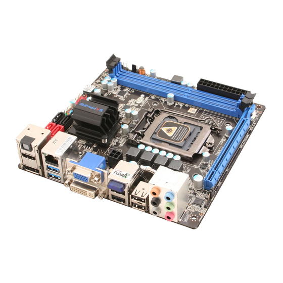
Page 9: Mainboard Layout
1-3 Mainboard Layout The following figure shows the location of components on the mainboard. See following page for description. Component on front of mainboard: Component on back of mainboard: ~ 5 ~... - Page 10 Item Component description CPU Socket 1155 Intel H67/H61 single Chip DDR3 DIMM Slots 1-2 PCI-E 2.0 x16 Slot 24-Pin ATX Power Connector 4-pin ATX_12V Power Connector Mainboard Battery SATA3 Connectors *2 (For H67 model) SATA2 Connectors *2 (For H61 model) SATA2 Connectors *2 Front Panel Header USB 2.0 Header *4...
- Page 11 I/O Back Panel The I/O back panel for this mainboard is shown below. When installing the mainboard into the computer case, use the bundled I/O shield to protect this back panel. Optical S/PDIF-Out This SPDIF (Sony & Philips Digital Interconnect Format) connector is used for digital audio transmission to external speakers/amplifier through an optical fiber cable.
- Page 12 USB 3.0 ports (two) USB 3.0 ports are backwardly compatible with USB 2.0 devices. Supports data transfer rates up to 4.8Gb/s (SuperSpeed). VGA Port The VGA female port provides connection to analogue VGA monitors. DVI-D Port The DVI-D (Digital Visual Interface-Digital) port provides a high-speed digital interconnection between the computer and its display device.
-
Page 13: Audio Ports
10. Audio Ports This mainboard provides 2, 6 or 8 channel audio. It is easy to differentiate between the audio functions by referring to the color of the jacks. Ports 2 channel 6 channel 8 channel Blue Line-In Line-In Line-In Lime Line-Out Front Stereo-Out... -
Page 14: Chapter 2 Installation
Chapter 2 Installation 2-1 Before You Begin Please take note of all precautions before you install anything on to the mainboard or change any of the mainboard settings. Turn off the power to your system and discharge your body’s static electric charge by touching a grounded surface—for example, the metal surface of the power supply—before performing any hardware procedure. -
Page 15: Installing The Cpu And Fan Heatsink
2-4 Installing the CPU and Fan Heatsink To install the CPU: 1. Open the socket lever by pushing the lever down and away from the socket. Remove the protective socket cover from the socket. Do not touch the socket contacts. Note: ... -
Page 16: Installing System Memory
2-5 Installing System Memory This mainboard has two 240-pin DIMM sockets for DDR3 memory. Supports 1GB, 2GB and 4GB DDR3 DIMMs up to max. 8GB Supports 1.5v DDR3-1066/1333 DIMMs with dual channel architecture. Memory configurations To use 1 DIMM: Install into either DIMM slot 1 or slot 2. To use 2 DIMMs: Install into DIMM slot 1 and DIMM slot 2. -
Page 17: Installing Expansion Cards
2-6 Installing Expansion Cards The mainboard provides one PCI Express 2.0 x16 slot and one Mini PCI-E slot. PCI-E2.0 x16 slot Mini PCIE slot (with x1 link) It’s located on the back side of mainboard. PCI-E Slot The design of this motherboard supports PCI-E Express x16 card complying with the PCI Express specification. -
Page 18: Connecting Cables
2-7 Connecting Cables This section takes you through all the necessary connections on the mainboard. Connecting Power Supply Cables 24-pin ATX Power PW1 is the main power supply connector. Make sure that the power supply cable pins are properly aligned with the connector on the mainboard. Firmly plug the power supply cable into the connector and make sure it is secure. -
Page 19: Connecting Serial Ata (Sata) Cables
Connecting Serial ATA (SATA) Cables Use SATA cables support Serial ATA protocol. Each cable can be used to connect one internal SATA drive to the mainboard. H67 model: The black coloured connectors (S3 and S4) are SATA 2.0 compliant and operate at speeds up to 3 Gb/s. -
Page 20: Connecting To The Internal Headers And Connectors
Connecting to the Internal Headers and Connectors Front Panel Header The front panel header on this motherboard is used to connect the front panel switches and LEDs. PWR_LED Attach the front panel power LED cable to these two pins of the connector. The Power LED indicates the system’s status. -
Page 21: Usb2.0 Headers
USB2.0 Headers This mainboard contains four (4) USB 2.0 ports that are exposed on the rear panel of the chassis. This mainboard also contains two 10-pin onboard header connectors that can be used to connect to four (4) external USB 2.0 devices. Refer to the following steps: 1. -
Page 22: Fan Headers
Fan Headers There are two fan headers (CPUFAN, PWRFAN) on the motherboard. They can be speed detected/controlled and displayed in the Hardware Monitor Configuration section of the CMOS Setup. The fans are automatically turned off after the system enters S3, S4 or S5 mode CPUFAN PWRFAN Note:... -
Page 23: Jumper Settings
2-8 Jumper Settings If the CMOS data becomes corrupted or you forgot the supervisor or user password, clear the CMOS data to reconfigure the system back to the default values stored in the ROM BIOS. To clear CMOS data, please follow the steps below. -
Page 24: Chapter 3 Configuring The Bios
Chapter 3 Configuring the BIOS This chapter provides information on the BIOS Setup program and allows you to configure the system for optimum use. 3-1 Select Boot Device Select Boot Device Menu allows you to set the first boot device without entering BIOS Setup. - Page 25 Note2: The BIOS options in this manual are for reference only. BIOS screens in manuals are usually the first BIOS version when the board is released and may be different from your purchased motherboard. Users are welcome to download the latest BIOS version from our official website ControlKeys Please check the following table for the function description of each Controlkey.
-
Page 26: Main Menu
3-3 Main Menu When entering the Aptio Setup Utility, the main menu screen appears. This main menu includes the system overview and displays the basic system configuration, such as BIOS information, memory size and system date/time. Aptio Setup Utility - Copyright (C) 2011 American Megatrends, Inc. Main Performance Advanced... -
Page 27: Performance Menu
3-4 Performance Menu The Performance menu allows you to specify your settings for CPU, memory, voltage control and overclocking. Press <Enter> to display the configuration options. Aptio Setup Utility - Copyright (C) 2011 American Megatrends, Inc. Main Advanced Chipset Boot Security Save &... -
Page 28: Memory Configuration
Graphics Core Ratio Limit Allows you to set a core ratio limit for graphics. Graphics Voltage Allows you to adjust the on board graphics voltage. Options: +0.000V ~+1.000V in 0.004V increments. CPU C6 Report Allows you to enable or disable CPU C6(ACPI C3) report to OS. Options: Enabled, Disabled. - Page 29 RAS# to CAS# Delay(tRCD) Set the RAS to CAS Delay time for Read/Write commands to the same bank. Options: 3 ~ 15. Row Precharge Time(tRP) Set the Row Precharge time. This is the Precharge-to-Active or Auto-to-Refresh of the same bank. Options: 3 ~ 15.
-
Page 30: Voltage Configuration
Voltage Configuration Aptio Setup Utility - Copyright (C) 2011 American Megatrends, Inc. Performance Voltage Configuration CPU Vcore CPU Vcore [+0mV] DIMM Voltage [Auto] DIMM DQA Voltage [Auto] DIMM DQB Voltage [Auto] CPU VTT [Auto] : Select Screen Select Item Enter: Select +/-: Change Opt. -
Page 31: Advanced Menu
3-5 Advanced Menu The Advanced menu items allow you to change the settings for the CPU, USB and other system devices. Press <Enter> to display the configuration options. Aptio Setup Utility - Copyright (C) 2011 American Megatrends, Inc. Main Performance Chipset Boot Security... -
Page 32: Pci Subsystem Settings
PCI Subsystem Settings Aptio Setup Utility - Copyright (C) 2011 American Megatrends, Inc. Advanced PCI Bus Driver Version V 2.03.00 Value to be programmed into PCI Latency Timer Register. PCI Common Settings PCI Latency Timer [32 PCI Bus Clocks] VGA Palette Snoop [Disabled] PCI Express Device Settings Relaxed Ordering... -
Page 33: Acpi Settings
Options: Auto, 128 Bytes, 256 Bytes, 512 Bytes, 1024 Bytes, 2048 Bytes, 4096 Bytes. Maximum Read Request Sets the Maximum Read Request of PCI Express Device or allows the System BIOS to select the value. Options: Auto, 128 Bytes, 256 Bytes, 512 Bytes, 1024 Bytes, 2048 Bytes, 4096 Bytes. -
Page 34: Cpu Configuration
CPU Configuration Aptio Setup Utility - Copyright (C) 2011 American Megatrends, Inc. Advanced CPU Configuration Number of cores to enable in Intel (R) Core (TM) i5-2400 CPU @ 3.10GHz each processor package. EMT64 Supported Max Processor Speed 3100 MHz Min Processor Speed 1600MHz Processor Speed 3100MHz... -
Page 35: Sata Configuration
capabilities provided by Intel Virtualization Technology. Options: Enabled, Disabled. Local X2API This item enables Local X2APIC function. Some OSes do not support this. Options: Enabled, Disabled. SATA Configuration Aptio Setup Utility - Copyright (C) 2011 American Megatrends, Inc. Advanced SATA Configuration (1)IDE Mode. -
Page 36: Usb Configuration
Staggered Spin-up Enables the AHCI supports Staggered Spin-up function. Options: Enabled, Disabled. External SATA Port Enables the external SATA port support. Options: Enabled, Disabled. Hot Plug Enables the SATA port hot plug support. Options: Enabled, Disabled. USB Configuration Aptio Setup Utility - Copyright (C) 2011 American Megatrends, Inc. Advanced USB Configuration Enables Legacy USB support;... -
Page 37: Super Io Configuration
EHCI Hand-off This is a workaround for OSes without EHCI hand-off support. The XHCI ownership change should be claimed by EHCI driver. Options: Enabled, Disabled. Part 60/64 Emulation Enables I/O port 60h/64h emulation support. This should be enabled for the complete USB keyboard legacy support for non-USB aware OSes. -
Page 38: H/W Monitor
Restore on AC Power Loss Enables your computer to automatically restart or return to its last operating status after power returns from a power failure. Options: Power off, Power on, Last State. EuP Function Enables the EuP (Energy Using Products) function, allows BIOS to switch off some power at S5 state to get system ready for the EuP requirement to reduce power consumption. -
Page 39: Onboard Device
CPU Fan Mode Setting This item controls the speed of the various fans on the motherboard. SmartFan: When you want the speed of the fans automatically controlled based on temperature. Manual Mode 1: To set the fan speed to a constant rate, the speed from 0% to 100%. -
Page 40: Chipset Menu
3-6 Chipset Menu The chipset menu items allow you to change the advanced chipset settings. Press <Enter> to display the sub-menu. Aptio Setup Utility - Copyright (C) 2011 American Megatrends, Inc. Main Performance Advanced Boot Boot Security Save & Exit Chipset North Bridge Parameters. - Page 41 Memory Slot 0/1 Displays the memory size of each individual slot. VT-d Allows you enable the chipset VT-d technology. Options: Enabled, Disabled. Initiate Graphic Adapter Select which graphics controller to use as the primary boot device. Options: PEG/IGD, IGD/PEG. Note: to install VIRTU, use IDG/PEG setting. IGD Memory Allows you select share memory size of internal graphics device.
-
Page 42: South Bridge
South Bridge Aptio Setup Utility - Copyright (C) 2011 American Megatrends, Inc. Chipset Enabled/Disabled the High SB Chipset Configuration Precision Event Timer. High Precision Event Timer Configuration High Precision Timer [Enabled] : Select Screen Select Item Enter: Select +/-: Change Opt. -
Page 43: Boot Menu
3-7 Boot Menu The Boot menu is used to configure the boot settings and the boot priority. Aptio Setup Utility - Copyright (C) 2011 American Megatrends, Inc. Main Performance Advanced Chipset Boot Security Save & Exit Boot Boot Configuration Number of seconds to wait for Setup Prompt Timeout setup activation key. - Page 44 Keep Current: To keep the current video mode. This will suppress option ROM messages. Option ROMs requiring interactive inputs may not work properly in this mode. Interrupt 19 Capture Allows specify if legacy PCI option ROMs are allowed to capture software interrupt 19h.
-
Page 45: Security Menu
3-8 Security Menu The Security menu allows you to change the system security settings. Aptio Setup Utility - Copyright (C) 2011 American Megatrends, Inc. Main Performance Advanced Chipset Boot Save & Exit Security Password Description Set setup Administrator Password. If ONLY the Administrator’s password is set, then this only limits access to Setup and is only asked for when entering Setup. -
Page 46: Save & Exit Menu
3-9 Save & Exit Menu The Save & Exit menu allows you to load the optimal default values for BIOS, and save or discard your changes to the BIOS items. Aptio Setup Utility - Copyright (C) 2011 American Megatrends, Inc. Main Advanced Chipset... - Page 47 Save as User Defaults This is used to save all current settings as user default. The current setup state can later be restored using Restore User Defaults. Restore User Defaults This is used to restore all tokens to settings previously stored by Save as User Defaults.
-
Page 48: Chapter 4 Device Driver Installation
Chapter 4 Device Driver Installation After the operating system has been installed, you need to install drivers for this mainboard. The support DVD that came with the motherboard contains necessary drivers and useful utilities that enhance the motherboard features. 4-1 Driver Install Insert the bundled driver DVD into your optical drive and the main menu will be... -
Page 49: Trixx Utility
4-2 TRIXX Utility TRIXX is a simple and easy-to-use utility that allows users to adjust system settings for overclocking in a Windows environment. The TRIXX utility includes three configurations for frequency, voltage and hardware monitoring. To install TRIXX Utility, run it from the Sapphire Utility page from the bundled DVD.
Need help?
Do you have a question about the Pure Platinum H67 and is the answer not in the manual?
Questions and answers