Table of Contents
Advertisement
Quick Installation Guide
Sapphire Pure Innovation 760G
PI-AM3RS760G2
AMD 760G/ Socket AM3 Series Mainboard
TRADEMARK
All products and company names are trademarks or registered trademarks of their
respective holders.
These specifications are subject to change without notice.
Manual Revision 1.0
October, 2010
Advertisement
Table of Contents

Related Manuals for Sapphire Audio Pure Innovation 760G


Summary of Contents for Sapphire Audio Pure Innovation 760G
- Page 1 Quick Installation Guide Sapphire Pure Innovation 760G PI-AM3RS760G2 AMD 760G/ Socket AM3 Series Mainboard TRADEMARK All products and company names are trademarks or registered trademarks of their respective holders. These specifications are subject to change without notice. Manual Revision 1.0 October, 2010 ...
- Page 2 Federal Communications Commission (FCC) Statement This device has been tested and found to comply with the limits for a Class B digital device, pursuant to Part 15 of FCC Rules. These limits are designed to provide reasonable protection against harmful interference in a residential installation. This equipment generates, uses and can radiate radio frequency energy and, if not installed and used in accordance with instructions contained in this manual, may cause harmful interference to radio and television communications.
- Page 3 Environmental Safety Considerations Avoid locations where it is dusty, humid or may suffer from extreme temperatures. Do not place the product in any area where it may become wet. The suitable ambient operating temperature is between 0 to 40 degrees centigrade. Dramatic changes in temperature may lead to malfunction due to constant thermal expansion and contraction from the solder spots that connect components to the PCB.
-
Page 4: Table Of Contents
TABLE OF CONTENTS Chapter 1 Introduction ..................1 1-1 Specification ........................ 1 1-2 Mainboard Layout ....................... 2 Chapter 2 Installation ..................3 2-1 Before You Begin ......................3 2-2 Installing the I/O Shield ....................3 2-3 Securing to the Chassis ....................3 2-4 Installing CPU and FAN sink .................. -
Page 5: Chapter 1 Introduction
Chapter 1 Introduction 11 Specification Spec. Description Design Micro ATX form factor, Size:24.5cm*20.0cm AMD 760G North Bridge Chipset Chipset AMD SB710 South Bridge Chipset Supports AMD Phenom™ II / Athlon™ II / Sempron™ 100 Series CPU’s in AM3 CPU Socket Socket Supports HT 3.0 Integrated ATI Radeon HD 3000 (Microsoft DX 10 Support) -
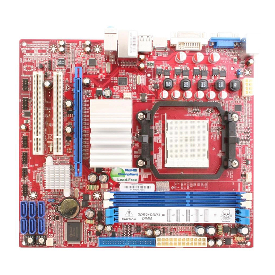
Page 6: Mainboard Layout
12 Mainboard Layout Rear I/O and layout for Pure Innovation 760G (PI-AM3RS760G2) Line-IN RJ-45 LAN Line-OUT PS/2 Mouse VGA Connector PS/2 Keyboard MIC-IN DVI Connector USB Connector KB/USB Power On (JP1) CPU FAN PS2 KB ATX 12V Power Connector /MS Port Connector ATX Power Conn. -
Page 7: Chapter 2 Installation
Chapter 2 Installation 21 Before You Begin Turn off the power to your system and discharge your body’s static electric charge by touching a grounded surface—for example, the metal surface of the power supply—before performing any hardware procedure. 22 Installing the I/O Shield Install the I/O shield before installing the mainboard in the chassis. Place the shield inside the chassis. -
Page 8: Installing System Memory
25 Installing System Memory This mainboard has two 240-pin DIMM slots for DDR3 memory. These slots support 1GB, 2GB and 4GB DDR3 DIMMs. Make sure that you install memory modules of the same type and density in the correct DIMM sockets for Dual-Channel mode. There must be at least one memory bank populated to ensure normal operation and always insert the memory module into DIMM slot 1 first. -
Page 9: Installing Expansion Cards
26 Installing Expansion cards The mainboard provides one PCI Express x16 slot and two PCI slots. PCI-E x16 Slot by 16-lane 32-bit PCI Slots PCI-E Slots To install a PCI Express card: 1. Place the card in an available PCI Express slot and press down on the card until it is completely seated in the slot. -
Page 10: Connectors
27 Connectors (1) Power Connector (24-pin block): ATXPWR1 ATXPWR1 is the main power supply ROW1 ROW2 connector. Make sure that the ROW1 ROW2 ROW1 ROW2 power supply cable and pins are 3.3V 3.3V properly aligned with the connector 3.3V -12V on the mainboard. Firmly plug the Soft Power On power supply cable into the connector and make sure it is... - Page 11 (3) PS/2 Mouse & PS/2 Keyboard Connector: KB These connectors are for a PS/2 keyboard and PS/2 Mouse. (4) USB Port connector: CN5/ UL1 for USB These are 4-pin connectors that connect USB devices to the system. (5) LAN Port connector: UL1 for RJ-45 LAN A standard RJ45 connector for network access supporting 10M/100 Mbps data transfer rate.
-
Page 12: Headers
(8) Serial-ATAII Port connector: SATA1,SATA 2,SATA3, SATA4, SATA5, SATA6 These allow connection of Serial ATA2 hard / optical disks to the mainboard using the Serial ATA2 IDE cables provided. (9) D-Sub 15-pin Connector: VGA 15-pin D_Sub VGA connector for attaching display devices such as CRT and LCD monitors. - Page 13 (2) USB Port Headers (9-pin): USB1/USB2 These headers are used for connecting the additional USB ports. By attaching an optional USB port cable, you can provide two additional USB ports on the back panel. P in 1 U SB P ort H eaders (3) Speaker connector: SPEAK1 This 4-pin connector connects to the case-mounted speaker.
- Page 14 (8) FAN Headers: SYSFAN1 (3-pin), SYSFAN2 (3-pin), CPUFAN (4-pin) These connectors support cooling fans up to 350mA (4.2 Watts). Depending on the fan manufacturer, the wire and plug may be different. The red wire should be positive, while the black should be ground. Connect the fan’s plug to the board taking into consideration the polarity of connector.
-
Page 15: Jumper Setting
29 Jumper Setting (1) Keyboard/USB function Enabled/Disabled: JP1 1-2 Closed KB/USB Power ON Disable (Default) 2-3 Closed KB/USB Power ON Enabled Keyboard/Mouse & USB Power On Setting (2) CMOS RAM Clear (3-pin): JBAT A battery must be used to retain the mainboard configuration in CMOS RAM. Connecting pins 1 and 2 of JBAT is the normal position, storing the CMOS data. -
Page 16: Chapter 3 Configuring The Bios
Chapter 3 Configuring the BIOS This chapter provides information on the BIOS Setup program and allows you to configure the system for optimum use. 31 Enter BIOS Setup The BIOS is the communication bridge between hardware and software. Correctly setting the BIOS parameters is critical to maintain optimal system performance. Use the following procedure to change BIOS settings. -
Page 17: Main Menu
32 Main Menu When entering the BIOS SETUP UTILITY, the main menu screen appears. The Main Menu allows you to select from 14 setup functions and 2 exit choices. Use arrow keys to select among the items and press <Enter> to accept or enter the sub-menu. CMOS Setup Utility – Copyright (C) 1985‐2005, American Megatrends, Inc. ... -
Page 18: Standard Cmos Features
Load Optimal Defaults Use this menu to load the BIOS default values these are setting for optimal performances system operations for performance use. Load Failsafe Defaults This menu uses a minimal performance setting, but the system would run in a stable way. -
Page 19: Advanced Bios Features
34 Advanced BIOS Features Use this menu to set the Advanced Features available on your system. CMOS Setup Utility – Copyright (C) 1985‐2005, American Megatrends, Inc. Advanced BIOS Features Advanced Settings Help Item WARNIG: Setting wrong values in below sections may cause system to walfunction. CPU Configuration Press Enter Hard Disk Drives Press Enter CD/DVD Drives Press Enter Quick Boot Enabled 1st Boot Device SATA:3M‐WDC WD3200A 2nd Boot Device CD/DVD:SS‐PHILIPS S Bootup Num‐Lock ON ACPI APIC support Enabled MPS Revision ... -
Page 20: Advanced Chipset Features
35 Advanced Chipset Features The Advanced Chipset Features Setup option is used to change the values of the chipset registers. These registers control most of the system options in the computer. CMOS Setup Utility – Copyright (C) 1985‐2005, American Megatrends, Inc. Advanced Chipset Features Help Item Memory Configuration Press Enter Internal Graphics Configuration Press Enter PCI Express Configuration ... -
Page 21: Internal Graphics Configuration
36 Internal Graphics Configuration CMOS Setup Utility – Copyright (C) 1985‐2005, American Megatrends, Inc. Internal Graphics Configuration Help Item Internal Graphics Configuration Option Internal Graphics Mode UMA Disabled UMA Frame Buffer Size Auto GFX Engine Clock Override Disabled Surround View Disabled FB Location Above 4G : Move Enter: Select +/‐/ : Value F10: Save ESC: Exit F1: General Help F5: Previous Values ... -
Page 22: Power Management Features
37 Power Management Features The Power Management Setup allows you to configure your system to most effectively save energy saving while operating in a manner consistent with your own style of computer use. CMOS Setup Utility – Copyright (C) 1985‐2005, American Megatrends, Inc. Power Management Features Power Management Features Help Item Enable/Disable SMI Power Management/APM Enabled based power Suspend Time Out ... -
Page 23: Miscellaneous Controls
38 Miscellaneous Controls Use this menu to specify your settings for Miscellaneous Control. CMOS Setup Utility – Copyright (C) 1985‐2005, American Megatrends, Inc. Miscellaneous Control Advanced PCI/PnP Setting Help Item Options WARNING: Setting wrong values in below sections may cause system to malfunction Clear NVRAM during System Boot Clear NVRAM No Plug & Play O/S No PCI LATENCY Timer 64 Allocate IRQ to PCI VGA Yes Palette Snooping Disabled PCI IDE Bus Master Disabled IRQ Resources Press Enter : Move Enter: Select +/‐/ : Value F10: Save ESC: Exit F1: General Help F5: Previous Values ... -
Page 24: Pc Health Status
39 PC Health Status This section shows the Status of you CPU, Fan, and Warning for overall system status. This is only available if there is Hardware Monitor onboard. CMOS Setup Utility – Copyright (C) 1985‐2005, American Megatrends, Inc. PC Health Status Advanced PCI/PnP Setting Help Item CPU Temperature :34℃/93℉ System Temperature :28℃/82℉ CPUFAN Speed : 3068 RPM ... -
Page 25: Thermal Throttling Function
310 Thermal Throttling Function The selection is set for activating the active CPU Thermal Protection by flexible CPU loading adjustment in the range of temperature you define. CMOS Setup Utility – Copyright (C) 1985‐2005, American Megatrends, Inc. Thermal Throttling Function CPU Thermal Throttling Disabled Help Item Option Disabled Enabled : Move Enter: Select +/‐/ : Value F10: Save ESC: Exit F1: General Help F5: Previous Values ... -
Page 26: Password Setting
CPU/HT Reference Clock Use this item to set CPU/HT Reference Clock. The optional setting range is: 190~400 MHz. PCI E Reference Clock Allows you to select PCIE reference clock. The enabled setting is 100. SB Reference Clock Allows you to select SB reference clock. The enabled setting is 100. Processor Voltage Allows you to select processor voltage. -
Page 27: Load Defaults
To change a Supervisor Password, following the same steps above to change your password. Change User Password To set a User Password: 1. In the password box, key in a password number, then press <Enter>. 2. Confirm the password when prompted. 3. -
Page 28: Changes And Exit
314 Changes and Exit Save Changes and Exit Ensures the values you selected are saved to the CMOS RAM. When you select this option, a confirmation window appears. Discard Changes and Exit Abandon all CMOS value changes and exit setup. When you select this option, a confirmation window appears. - 24 -... -
Page 29: Chapter 4 Driver Installation
Chapter 4 Driver Installation After the operating system has been installed, you need to install drivers for this mainboard. The support CD that came with the motherboard contains necessary drivers and useful utilities that enhance the motherboard features. <Main Page> Insert the bundled driver CD into your optical drive and the main menu will be displayed on your PC...
Need help?
Do you have a question about the Pure Innovation 760G and is the answer not in the manual?
Questions and answers