Table of Contents
Advertisement
Advertisement
Table of Contents

Related Manuals for Sapphire Audio Pure Black 990FX


Summary of Contents for Sapphire Audio Pure Black 990FX
- Page 1 User’s Manual Sapphire Pure Black 990FX AMD 990FX/SB950 for AM3b Socket Mainboard TRADEMARK All products and company names are trademarks or registered trademarks of their respective holders. These specifications are subject to change without notice. Manual Revision 1.0 September 23, 2011...
- Page 2 Federal Communications Commission (FCC) Statement This device has been tested and found to comply with the limits for a Class B digital device, pursuant to Part 15 of FCC Rules. These limits are designed to provide reasonable protection against harmful interference in a residential installation.
-
Page 3: Table Of Contents
Table of Contents Chapter 1 Introduction ..............1 1-1 Mainboard Specifications ............1 1-2 Package Contents ..............4 1-3 Mainboard Layout ..............5 Chapter 2 Installation ............... 9 2-1 Before You Begin ..............9 2-2 Installing the I/O Shield ............9 2-3 Securing to the Chassis ............ - Page 4 Frequency Configuration ............29 Voltage Configuration ............30 3-5 Advanced Menu ..............32 PCI Subsystem Settings ............33 PCI Express Settings ............. 34 ACPI Settings ................ 36 S5 RTC Wake Settings ............37 CPU Configuration ..............38 CPU Information ..............39 Onboard Device ..............
-
Page 5: Chapter 1 Introduction
Chapter 1 Introduction 1-1 Mainboard Specifications ® Supports AMD Phenom™II /Athlon™II /Sempron™ 100 Series processor in ® the AMD socket AM3+(AM3b) Supports HyperTransport™ 3.0 and data transfer rate up to 5.2 GT/s ® AMD Cool ’n’ Quiet™ technology Chipset ®... - Page 6 From two Marvell 9172 controller: - Controller for front: Two SATA3 ports with 6Gb/s data transfer rate with RAID 0 and 1 - Controller for Rear: Two SATA3 ports including one eSATA port - Supports AHCI (Advanced Host Controller Interface) Onboard LAN ...
- Page 7 2 x USB 3.0 ports 6 audio jacks Internal I/O Connectors 1 x 24-pin ATX power connector 1 x 8-pin ATX 12V power connector 1 x 4-pin Molex power connector 9 x SATA3 connectors (six from AMD SB950 and three from Marvell controller) ...
-
Page 8: Package Contents
1-2 Package Contents Your Sapphire mainboard comes with the following accessories. 1. Mainboard 2. I/O Shield 3. Quick Installation Guide 4. Driver CD 5. USB3.0 Front Panel Cable 6. SATA Data Cable *6 (Optional) ~ 4 ~... -
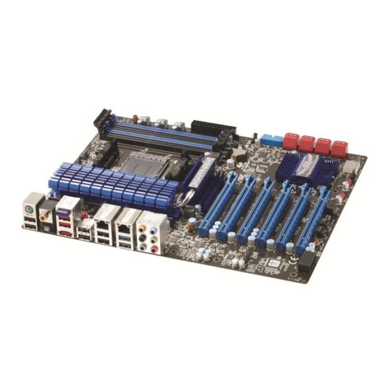
Page 9: Mainboard Layout
1-3 Mainboard Layout The following figure shows the location of components on the mainboard. See following page for description. ~ 5 ~... - Page 10 Item Component description AMD CPU Socket AM3b AMD RD990FX Chip AMD SB950 Chip DDR3 DIMM Slots 1-4 PCI-E 2.0 x16 Slot *6 24-Pin ATX Power Connector 8-pin ATX_12V Power Connector 4-pin Power Connector USB 3.0 Header *2 SATA3 Connectors *9 Front Panel Header USB 2.0 Header *4 PC Speaker...
- Page 11 I/O Back Panel The I/O back panel for this mainboard is shown below. When installing the mainboard into the computer case, use the bundled I/O shield to protect this back panel. PS/2 Keyboard/Mouse Port This connector is used for a keyboard or mouse. You can plug a PS/2 keyboard or mouse directly into this connector.
- Page 12 Dual LAN Ports with LEDs The mainboard provides two standard RJ-45 jacks for connecting to a Local Area Network (LAN). Two LEDs are built into the RJ-45 LAN connector. These LEDs indicate the status of the LAN. LED Color LED state Indicates LAN link is not established Green...
-
Page 13: Chapter 2 Installation
Chapter 2 Installation 2-1 Before You Begin Please take note of all precautions before you install anything on to the mainboard or change any of the mainboard settings. Turn off the power to your system and discharge your body’s static electric charge by touching a grounded surface—for example, the metal surface of the power supply—before performing any hardware procedure. -
Page 14: Installing The Cpu And Fan Heatsink
2-4 Installing the CPU and Fan Heatsink Follow the steps below to install the CPU & cooler correctly. 1. Open the socket lever and rise to a 90 degree angle. 2. Align the CPU pin one (small triangle marking) and gently insert the CPU into the socket then close the socket lever. -
Page 15: Installing System Memory
2-5 Installing System Memory This mainboard has four 240-pin DIMM sockets for DDR3 memory. These slots support 1GB, 2GB and 4GB DDR3 DIMMs up to max. 16GB Make sure that you install memory modules of the same type and density in different channel DIMM slots for Dual-Channel mode. -
Page 16: Installing Expansion Cards
2-6 Installing Expansion Cards The mainboard provides six PCI Express 2.0 x16 slots that complying with the PCI Express specifications. PCIE1_X16/8 PCI-E2.0 x16 slot (with x16/x8 link) PCIE2_X4 PCI-E2.0 x16 slot (with x4 link) PCIE3_X16/8 PCI-E2.0 x16 slot (with x16/x8 link) PCIE4_ X8 PCI-E2.0 x16 slot (with x8 link) PCIE5_X8... -
Page 17: Connecting Cables
To install a PCI Express card: Place the card in an available PCI Express slot and press down on the card until it is completely seated in the slot. If the card is not seated properly, it could cause a short across the pins. Secure the card’s metal bracket to the chassis back panel with a screw. -
Page 18: Connecting Serial Ata (Sata) Cables
Connecting Serial ATA (SATA) Cables SATA cables support the Serial ATA protocol. Each cable can be used to connect one SATA drive to the mainboard. The S1 to S3 connectors are controlled by the AMD SB950 chip and work at speeds of up to 6 Gb/s and support RAID 0, 1, 10, 5 function. -
Page 19: Connecting To The Internal Headers And Connectors
Connecting to the Internal Headers and Connectors Front Panel Header The front panel header on this motherboard is used to connect the front panel switches and LEDs. PWR_LED Attach the front panel power LED cable to these two pins of the connector. The Power LED indicates the system’s status. -
Page 20: Usb2.0 Headers
USB2.0 Headers This mainboard contains four (4) USB 2.0 ports that are exposed on the rear panel of the chassis. This mainboard also contains four 10-pin onboard header connectors that can be used to connect to eight (8) external USB 2.0 devices. Refer to the following steps: 1. -
Page 21: Cfpa Header
CFPA Header This header allows you to connect the front panel audio. The audio connector supports HD audio standard. S/PDIF Header This header is used to connect S/PDIF (Sony & Philips Digital Interconnect Format) interface for digital audio transmission. ~ 17 ~... - Page 22 Fan Headers There are Five fan headers (CPUFAN, SYSFAN, SYSFAN1, PWRFAN, CHAFAN) on the motherboard. Three of these fans (CPUFAN, PWRFAN, CHAFAN) can be speed detected/controlled and displayed in the Hardware Health Configuration section of the CMOS Setup. The fans are automatically turned off after the system enters S3, S4 or S5 mode.
-
Page 23: Diagnostics Led
2-8 Diagnostics LED This mainboard provides a two-digit POST code to show why the system may be failing to boot. It is useful during a troubleshooting situation. This Debug LED will also display the current CPU temperature after the system has fully booted into the operating system. -
Page 24: Onboard Buttons
2-10 Onboard Buttons These onboard buttons include Clear CMOS, RESET and POWER, which allow you to easily clear the CMOS, reset the system and turn on/off the system. Clear CMOS Button The mainboard uses the CMOS RAM to store some of the system configuration. The CMOS can be cleared by pressing the Clear CMOS button. -
Page 25: Dual Bios Switch
2-11 Dual BIOS Switch This mainboard includes dual onboard BIOS, (Primary and Secondary BIOS), When the primary BIOS is corrupted or has failed, you can use the secondary BIOS to take over on the next system boot to ensure normal system operation. ... -
Page 26: Chapter 3 Configuring The Bios
Chapter 3 Configuring the BIOS This chapter provides information on the BIOS Setup program and allows you to configure the system for optimum use. 3-1 Select Boot Device Select Boot Device Menu allows you to set the first boot device without entering BIOS Setup. - Page 27 upon the bottom of the display during Power On Self Test (POST). Press F1 to continue, DEL to enter Setup. Pressing Del takes you to the BIOS Setup Utility. Note1: It is strongly recommended that you do not change the default BIOS settings.
-
Page 28: Main Menu
3-3 Main Menu When entering the BIOS Setup Utility, the main menu screen appears. This main menu includes the system overview and displays the basic system configuration, such as BIOS information, memory size and system date/time. Set the Date. Use BIOS Information Tab to switch BIOS Vendor... -
Page 29: Performance Menu
Access Level This item is used to limit the user access level. 3-4 Performance Menu The Performance menu allows you to specify your settings for CPU, memory, voltage control and overclocking. Press <Enter> to display the configuration options. Performance Settings Memory Configuration Memory Configuration Frequency Configuration... -
Page 30: Memory Configuration
Memory Configuration Memory Multiplier [Auto] Allows you to select Memory SPD Profile [Auto] the memory CAS# Latency (tCL) multiplier. RAS# to CAS# Delay(tRCD) Row Precharge Time(tRP) RAS# Active Time(tRAS) Active to Active/Refresh Delay (tRC) Write Recovery Time(tWR) Write to Read Delay(tWTR) Active to Active Delay(tRRD) Read CAS# Precharge(tRTP) Four Active Windows Delay(tFAW) - Page 31 RAS# Active Time(tRAS) Set the minimum RAS# active time. Options: Auto(24), 15 ~ 30. Active to Active/Refresh Delay (tRC) Set the Row Cycle Time. Options: Auto(33), 11 ~ 42. Write Recovery Time(tWR) Set the internal Write to Read recovery time. Options: Auto(10), 5 ~ 12.
-
Page 32: Memory Strength Settings
Memory Strength Settings CKE Drive Strength [Auto] CS/ODT Drive Strength [Auto] ADDR/CMD Drive Strength [Auto] MEMCLK Drive Strength [Auto] Data Drive Strength [Auto] DQS Drive Strength [Auto] Processor ODT [Auto] CKE Drive Strength Select the memory Clock Enable signal strength Options: Auto, 1.0X, 1.25X, 1.5X, 2.0X CS/ODT Drive Strength Select the memory modules bank signals strength... -
Page 33: Frequency Configuration
Frequency Configuration Set CPU Frequency Frequency Configuration Ranges: 200 - 400 CPU Frequency (MHz) CPU Ratio [Auto] CPU_NB Frequency [Auto] HT Link Frequency [Auto] 1.352 3027 1.479 1.104 8192 1332 11.880 CPU Frequency (MHz) This item allows you to select the CPU frequency (in MHz). Options: 200 ~ 400. -
Page 34: Voltage Configuration
Voltage Configuration Voltage Configuration CPU Vcore [Auto] CPU_NB [Auto] CPU_NB HT Link [1.200V] CPU VDDR [1.200V] VDIMM [1.500V] NB Voltage [1.100V] SB FC [1.800V] SB Vcore [1.100V] DIMM DQ Voltage [+0mV] DIMM CA Voltage [+0mV] PWM Frequency [150Khz] 1.352 3027 1.479 8192 1.104... - Page 35 NB Voltage Allows you to adjust the North Bridge voltage. Options: 1.100V ~1.400V in 0.010V SB FC Allows you to adjust the South Bridge FC voltage. Options: 1.800V ~ 3.375V in 0.025V SB VCore Allows you to adjust the South Bridge VCore voltage. Options: 1.100V ~ 1.800V in 0.025V DIMM DQ Voltage Allows you to adjust the DQ Voltage of DIMM Slot voltage.
-
Page 36: Advanced Menu
3-5 Advanced Menu The Advanced menu items allow you to change the settings for the CPU, USB and other system devices. Press <Enter> to display the configuration options. Enables or disable Legacy OpROM Support Boot option for Launch PXE OpROM [Disabled] legacy network Launch Storage OpROM... -
Page 37: Pci Subsystem Settings
PCI Subsystem Settings In case of multiple PCI Bus Driver Version V 2.04.00 Option ROMs (Legacy and EFI Compatible), PCI Option ROM Handling specifies what PCI PCI ROM Priority [EFI Compatible ROM] Option ROM to launch. PCI 64bit Resources Handling Above 4G Decoding [Disabled] PCI Express Settings... -
Page 38: Pci Express Settings
PCI Express Settings PCI Express Device Settings Relaxed Ordering [Disabled] Extended Tag [Disabled] No Snoop [Enabled] Maximum Payload [Auto] Maximum Read Request [Auto] PCI Express Link Settings ASPM Support [Disabled] WARNING: Enabling ASPM may cause some PCI-E devices to fail Extended Synch [Disabled] Link Training Retry... - Page 39 ASPM Support Sets the ASPM level, select ‚Force L0‛ can force all links to L0 state. Options: Disabled, Auto, Force L0. Extended Synch If select ‚Enabled‛, allows generation of Extended Synchronization patterns. Options: Enabled, Disabled. Link Training Retry Defines number of Retry attempts software will take to retrain the link if previous training attempt was unsuccessful.
-
Page 40: Acpi Settings
ACPI Settings ACPI Settings Enable ACPI Auto Configuration [Disabled] Enable Hibernation [Enabled] ACPI Sleep State [S3 (Suspend to RAM)] Lock Legacy Resources [Disabled] 1.352 3027 1.479 8192 1.104 11.880 1332 Enable ACPI Auto Configuration Enables BIOS ACPI auto configuration. Options: Enabled, Disabled. Enable Hibernation Enables system ability to Hibernate (OS/S4 Sleep Sate). -
Page 41: S5 Rtc Wake Settings
S5 RTC Wake Settings Enable or disable Wake system with Fixed Time [Disabled] system wake on alarm event. When Wake system with Dynamic Time [Disabled] enabled, system will wake on the hr:min:sec specified. 1.352 3027 1.479 1.104 8192 1332 11.880 Wake system with Fixed Time Enable or disable system wake on alarm event. -
Page 42: Cpu Configuration
CPU Configuration Disabled for CPU Configuration Windows XP Limit CPUID Maximum [Disabled] AMD Cool’n’Quiet Technology [Enabled] [Disabled] [Enabled] ACPI SRAT table [Enabled] Turbo Core [Auto] Unlock Core [Disabled] Unlock Leveling Mode [Automatic mode] CPU Information 1.352 3027 1.479 1.104 8192 11.880 1332 Limit CPUID Maximum... -
Page 43: Cpu Information
Turbo Core Enables the processor cores to run faster than marked frequency in specification condition. Options: Enabled, Disabled. Unlock Core This item is used to unlock the CPU core. This depends on the CPU ability and characteristic. Options: Enabled, Disabled. Core Leveling Mode Use this item to select the number of cores to enable in each processor package. -
Page 44: Onboard Device
Onboard Device Enable or Disabled Onboard Device control Bluetooth Bluetooth [Enabled] Marvell Gigabit LAN 0 [Enabled] Marvell Gigabit LAN 1 [Enabled] Asmedia USB3.0 Controller [Enabled] Asmedia USB3.0 Controller (BP) [Enabled] Marvell SATA3 Controller [Enabled] SATA 6/7 AHCI/RAID Mode [AHCI] Marvell SATA3 Controller (BP) [Enabled] HD Audio Azalia Device [Enabled]... -
Page 45: Ide Configuration
RAID Mode: Create a RAID 0 and 1 configuration AHCI Mode: Use the AHCI (Advanced Host Controller Interface) to enable advanced SATA features for improved performance with NCQ and Hot-plug features Marvell SATA3 Controller (BP) Enables the onboard Marvell SATA3 controller of back panel. Options: Enabled, Disabled. -
Page 46: Usb Configuration
USB Configuration Enables Legacy USB USB Configuration support; AUTO option disables legacy support USB Devices: if no USB devices are 1 Keyboard, 1 Mouse connected, DISABLED option will keep USB Legacy USB Support [Enabled] devices available only USB3.0 Support [Enabled] for EFI application. -
Page 47: Super Io Configuration
USB transfer time-out The time-out value for control, bulk, and interrupt transfers. Options: 1 sec, 5 sec, 10 sec, 20 sec. Device reset time-out Sets USB mass storage devices start unit command time-out. Options: 10 sec, 20 sec, 30 sec, 40 sec. Device power-up delay Maximum time the device will take before it properly reports itself to the Host controller. -
Page 48: H/W Monitor
EuP Function Enables the EuP (Energy Using Products) function, allows BIOS to switch off some power at S5 state to get system ready for the EuP requirement to reduce power consumption. Options: Enabled, Disabled. H/W Monitor PC Health Status PWM Fan (4 pin) CPU Temperature : +49 C Linear Fan (3 pin) -
Page 49: Smart Fan Configuration
Smart Fan Configuration CPU Fan Type [PWM FAN (4 pin)] CPU Fan Mode Setting [SmartFan] Temperature Limit of Highest Temperature Limit of Lowest Fan Highest setting Fan Lowest setting Power Fan Mode Setting [SmartFan] Temperature Limit of Highest Temperature Limit of Lowest Fan Highest setting Fan Lowest setting Chassis Fan Mode Setting... -
Page 50: Chipset Menu
3-6 Chipset Menu The chipset menu items allow you to change the advanced chipset settings. Press <Enter> to display the sub-menu. North Bridge North Bridge Parameters South Bridge 1.352 3027 1.479 1.104 8192 1332 11.880 ~ 46 ~... -
Page 51: North Bridge
North Bridge IOMMU is supported North Bridge Configuration on LINUX based system to convert IOMMU Mode [Disabled] 32bit I/O to 64bit Memory Configuration MMIO. Memory Information Total Memory: 8192 MB (DDR3) DIMM Slot1 Information 1.352 3027 1.479 8192 1.104 11.880 1332 IOMMU Mode IOMMU is supported on LINUX based system to convert 32bit I/O to 64bit... -
Page 52: Memory Configuration
Memory Configuration Memory Configuration Bank interleaving [Auto] Channel interleaving [Auto] Memory Hole Remapping [Auto] Bank Interleaving Bank Interleaving is an important parameter for improving overclocking capability of memory. It allows system to access multiple banks simultaneously. Options: Auto, Disabled. Channel Interleaving Enables or disables memory channel interleaving. -
Page 53: South Bridge
South Bridge SB CIM Version 1.1.1.1 Options for SATA Configuration SB SATA Configuration SB USB Configuration 1.352 3027 1.479 8192 1.104 11.880 1332 SB SATA Configuration OnChip SATA Channel [Enabled] OnChip SATA Type [AHCI] SATA IDE Combined Mode [Disabled] OnChip SATA Channel Enables onboard SATA Channel. -
Page 54: Sb Usb Configuration
IDE Mode: Use the SATA hard disk drivers as Parallel ATA storage devices. RAID Mode: Create a RAID 0, 1, 0+1, 5 configuration AHCI Mode: Use the AHCI (Advanced Host Controller Interface) to enable advanced SATA features for improved performance with NCQ and Hot-plug features SATA IDE Combined Mode Enables SATA and IDE Combined mode. -
Page 55: Boot Menu
3-7 Boot Menu The Boot menu is used to configure the boot settings and the boot priority. Number of seconds to Boot Configuration wait for setup Setup Prompt Timeout activation key. Bootup NumLock State [On] 65535(0xFFFF) means indefinite waiting. Quiet Boot [Disabled] Fast Boot [Disabled]... - Page 56 GateA20 Active This feature determines how Gate A20 is used to address memory above 1MB. Upon Request: GA20 can be disabled using BIOS services. Always: Do not allow disabling GA20. Option ROM Message Sets display mode for Option ROM. Force BIOS: To force to a BIOS-compatible output. This will show the option ROM messages.
-
Page 57: Security Menu
3-8 Security Menu The Security menu allows you to change the system security settings. Password Description Set setup Administrator Password. If ONLY the Administrator’s password is set, then this only limits access to Setup and is only asked for when entering Setup. If ONLY the User’s password is set, then this is a power on password and must be entered to boot or enter setup. -
Page 58: Save & Exit Menu
3-9 Save & Exit Menu The Save & Exit menu allows you to load the optimal default values for BIOS, and save or discard your changes to the BIOS items. Save Changes and Exit Exit system setup Discard Changes and Exit after saving the Save Changes and Reset changes. - Page 59 Discard Changes Allows you to discard the selections you made. Restore Defaults The restore defaults are the factory settings of this motherboard. Save as User Defaults This is used to save all current settings as user default. The current setup state can later be restored using Restore User Defaults.
-
Page 60: Chapter 4 Driver Installation
Chapter 4 Driver Installation After the operating system has been installed, you need to install drivers for this mainboard. The support DVD that came with the motherboard contains necessary drivers and useful utilities that enhance the motherboard features. 4-1 Driver Install Insert the bundled driver DVD into your optical drive and the main menu... -
Page 61: Trixx Utility
4-2 TRIXX Utility TRIXX is a simple and easy-to-use utility that allows users to adjust system settings for overclocking in a Windows environment. The TRIXX utility includes three configurations for frequency, voltage and hardware monitoring. To install TRIXX Utility, run it from the Sapphire Utility page from the bundled DVD. -
Page 62: Hardware Monitor Gadget
4-3 Hardware monitor gadget This Hardware monitor gadget directly appears in windows screen after TriXX installation is completed. It can be used to help keep track of temperatures of CPU, System and fan speed of CPU, System and voltages of CPU, System. Displays hardware monitor temperature. -
Page 63: S_Bios Flash Utility
4-4 S_BIOS Flash Utility This mainboard provides a BIOS update tool. The S_BIOS allows you to update the system BIOS without having to enter MS-DOS or Windows environment. Embedded in the BIOS, the S_BIOS is simple and easy-to-use utility to flash BIOS. - Page 64 Setp3: For Update BIOS form Drive, Select the BIOS update file and press <OK> to start update. If the BIOS file stored in USB device, please must first insert USB device before turning on the system and make sure the BIOS update file matches your mainboard model.
- Page 65 Setp6: For Save BIOS to Drive, allows you to save the current BIOS file. If the BIOS file stored in USB device, please must first insert USB device before turning on the system. Setp7: To Save BIOS to Drive, Select the stored location and press <OK> to start saving BIOS file.
-
Page 66: Chapter 5 Post Code
Chapter 5 POST Code This chapter provides the Aptio POST Codes List for the mainboard during the BIOS pre-boot process. The POST Codes are displayed on the Debug LED readout located directly onboard the mainboard. Please refer to following ‚boot phases‛, which may apply to various status code &... - Page 67 OEM initialization before microcode loading Microcode loading AP initialization after microcode loading North Bridge initialization after microcode loading South Bridge initialization after microcode loading OEM initialization after microcode loading Cache initialization SEC Error Codes 0C – 0D Reserved for future AMI SEC error codes Microcode not found Microcode not loaded ...
- Page 68 Post-Memory South Bridge initialization (South Bridge module specific) Post-Memory South Bridge initialization (South Bridge module specific) Post-Memory South Bridge initialization (South Bridge module specific) 3F-4E OEM post memory initialization codes DXE IPL is started PEI Error Codes Memory initialization error. Invalid memory type or incompatible memory speed Memory initialization error.
- Page 69 DXE Phase Status Code Description DXE Core is started NVRAM initialization Installation of the South Bridge Runtime Services CPU DXE initialization is started CPU DXE initialization (CPU module specific) CPU DXE initialization (CPU module specific) CPU DXE initialization (CPU module specific) CPU DXE initialization (CPU module specific) PCI host bridge initialization North Bridge DXE initialization is started...
- Page 70 IDE Reset IDE Detect IDE Enable SCSI initialization is started SCSI Reset SCSI Detect SCSI Enable Setup Verifying Password Start of Setup Reserved for ASL (see ASL Status Codes section below) Setup Input Wait Reserved for ASL (see ASL Status Codes section below) Ready To Boot event Legacy Boot event Exit Boot Services event...
Need help?
Do you have a question about the Pure Black 990FX and is the answer not in the manual?
Questions and answers