Table of Contents
Advertisement
Federal Communications Commission (FCC) Statement
This equipment has been tested and found to comply with the limits for a Class B digital
device, pursuant to Part 15 of FCC Rules. These limits are designed to provide reasonable
protection against harmful interference in a residential installation. This equipment
generates, uses and can radiate radio frequency energy and, if not installed and used in
accordance with instructions contained in this manual, may cause harmful interference
to radio and television communications. However, there is no guarantee that interference
will not occur in a particular installation.
If this equipment does cause harmful interference to radio or television reception, which
can be determined by turning the equipment off and on, the user is encouraged to try to
correct the interference by one or more of the following measures:
- REORIENT OR RELOCATE THE RECEIVING ANTENNA
- INCREASE THE SEPARATION BETWEEN THE EQUIPMENT AND THE RECEIVER
- CONNECT THE EQUIPMENT INTO AN OUTLET ON A CIRCUIT DIFFERENT FROM
THAT OF THE RECEIVER
- CONSULT THE DEALER OR AN EXPERIENCED AUDIO/TELEVISION TECHNICIAN
NOTE: Connecting this device to peripheral devices that do not comply with Class B
requirements, or using an unshielded peripheral data cable, could also result in
harmful interference to radio or television reception.
The user is cautioned that any changes or modifications not expressly approved
by the party responsible for compliance could void the user‟s authority to operate
this equipment.
To ensure that the use of this product does not contribute to interference, it is
necessary to use shielded I/O cables.
Copyright
This manual is copyrighted with all rights reserved. No portion of this manual may be
copied or reproduced by any means.
While every precaution has been taken in the preparation of this manual, no responsibility
for errors or omissions is assumed. Neither is any liability assumed for damages resulting
from the use of the information contained herein.
Trademarks
All brand names, logos and registered trademarks mentioned are property of their
respective owners.
Electronic Emission Notices
Advertisement
Table of Contents

Related Manuals for Sapphire Audio PE-AM2RS690V2


Summary of Contents for Sapphire Audio PE-AM2RS690V2
-
Page 1: Electronic Emission Notices
Electronic Emission Notices Federal Communications Commission (FCC) Statement This equipment has been tested and found to comply with the limits for a Class B digital device, pursuant to Part 15 of FCC Rules. These limits are designed to provide reasonable protection against harmful interference in a residential installation. -
Page 2: Table Of Contents
Cable for Serial ATA II Rear External I/O Shield Sapphire PE-AM2RS690V2 Motherboard User‟s Manual Environmental Protection Announcement Do not dispose this electronic device into the trash while discarding. To minimize pollution and ensure environment protection of mother earth, please recycle. -
Page 3: Features Of Motherboard
Features of motherboard The AMD 690V Series motherboards are based on the latest AMD 690V Chipset and SB600 chipset which supports the new generation innovative 64-bit AMD Socket AM2 dual core multi-tasking Socket AM2 Athlon64 X2 processors and dual core AMD Phenom™ processors. -
Page 4: Special Design Of Motherboard
Special Features of Motherboard CPU Smart Fan---( The Noise Management System ( ) ) Only support 4-pin CPU cooler It‟s never been a good idea to gain the performance of your system by sacrificing its acoustics. CPU Smart Fan Noise Management System is the answer to control the noise level needed for now-a-day‟s high performance computing system. -
Page 5: Specification
Specification Spec Description Design Micro ATX form factor 4 layers PCB size: 24.4 cm*21.0cm or 24.4*19.3cm Chipset AMD 690V Chipset and AMD SB600 Chipset Support 64bit AMD AM2 940-Pin package utilizes Flip-Chip Pin Grid Array package compatible processor CPU Socket AM2 ... -
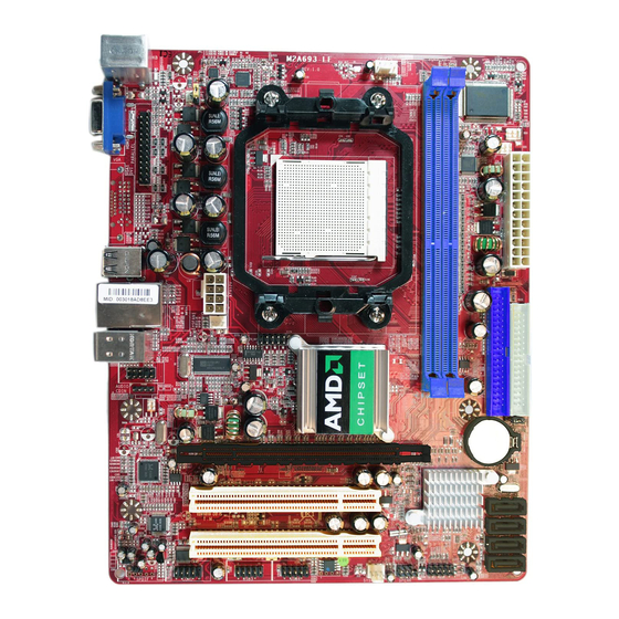
Page 6: Motherboard Layout
Motherboard Layout Keyboard/USB Power CPU Socket AM2 CPU FAN (JP1) AMD Phenom™ Ready PS2 KB/Mouse Port I/O Controller Chip Optional VGA DDR2 Socket x 2 Parallel ATX Power Conn. Connector Optional DVI USB Port ATX 12V Power Connector ATA 133 IDE RJ45 Over Conn. -
Page 7: Hardware Installation
Hardware Installation Install Socket AM2 / AM2 + Supported AMD Processor This motherboard provides a 940-pin surface mount, Zero Insertion Force (ZIF) socket, referred to as the mPGA940 socket supports AMD Athlon64 processor in the 940 Pin package utilizes Flip-Chip Pin Grid Array package technology. The CPU that comes with the motherboard should have a cooling FAN attached to prevent overheating. - Page 8 Recommend DIMM Module Combination One DIMM Module ----Plug in DIMM1 Two DIMM Modules---Plug in DIMM1 and DIMM2 or DIMM3 and DIMM4 for Dual channel function of 4-DIMM Design motherboard and Plug in DIMM1 and DIMM2 for Dual channel function of 2-DIMM Design motherboard. Four DIMM Modules---Plug in DIMM1/DIMM2/DIMM3/DIMM4.
-
Page 9: Expansion Cards
Expansion Cards The motherboards offer one PCI-Express x16 graphics slot of 4Gbyte/sec data transfer rate at each relative direction which gets 3.5 times of bandwidth more than AGP 8X and it‟s up to a peak concurrent bandwidth of 8Gbyte/sec at full speed to guarantee the ultimate GPU computing performance. -
Page 10: Connectors
Connectors, Headers & Jumpers Setting Connectors Power Connector (24-pinblock) ROW1 ROW2 ATXPWR1 ROW1 ROW2 ROW1 ROW2 ATX Power Supply connector: This is a 3.3V 3.3V new defined 24-pins connector that 3.3V -12V usually comes with ATX case. The ATX Soft Power On Power Supply allows using soft power on momentary switch that connect from the front panel switch to 2-pins Power On... - Page 11 PS/2 Line-IN 10/100 LAN Mouse Line-OUT MIC-IN PS/2 USB1 Keyboard (7) Floppy drive Connector (34-pin block): FDD1 This connector supports the provided floppy drive ribbon cable. After connecting the single plug end to motherboard, connect the two plugs at other end to the floppy drives. (8) Primary IDE Connector (40-pin block): IDE1 Pin 1 This connector connects to the next set of Master and Slave...
- Page 12 (10) D-Sub 15-pin Connector: VGA VGA is the 15-pin D-Subminiature female connector; it is for the display devices, such as the CRT monitor, LCD monitor and so on. (11) DVI: Digital Visual Interface (Optional) This interface standard designed to maximize the visual quality of digital display devices such as flat panel LCD computer displays and digital projectors.
-
Page 13: Headers
Headers (1) Line-Out/MIC Header for Front Panel (9-pin): AUDIO1 These headers connect to Front Panel Line-out, MIC connector with cable. Without install the cable, this header default setting is 5-6 short, 9-10 short. When you install the cable you have take off these jumpers. AUDIO AUDIO Pin 1... - Page 14 This 2-pin connector connects to the case-mounted power switch to power ON/OFF the system. (8) FAN Power Headers: SYSFAN1, SYSFAN2 (3-pin), CPUFAN (4-pin) These connectors support cooling fans of 350mA (4.2 Watts) or less, depending on the fan manufacturer, the wire and plug may be different. The red wire should be positive, while the black should be ground.
-
Page 15: Bios & Setup
BIOS & SETUP BIOS Setup Utility About the Phoenix-Award BIOS Setup Utility The motherboard uses the latest Award BIOS with support for Windows Plug and Play. The CMOS chip on the motherboard contains the ROM setup instructions for configuring the motherboard BIOS. The BIOS ( Basin Input and Output System ) Setup Utility displays the system‟s configuration status and provides you with options to set system parameters. -
Page 16: Setup Sata Raid
Main Menu Once you enter the Award BIOS CMOS Setup Utility, the Main Menu will appear one the screen. The Main Menu allows you to select from various setup functions and two exit choices. Use the arrow keys to select among the items and press <Enter> to accept and enter the sub-menu. Phoenix –... - Page 17 RAID AHCI ™ BIOS Version 2.5.1540.18 © 2004-2005 ATI Technology , Inc. All rights reserved. No Array is defined… Press <Ctrl-F> to enter FastBuild ™ Utility… 2. Press the Ctrl-F keys to display the FastBuild Utility Main Menu (below). FastBuild ™ Utility © 2004-2005 ATI Technology, Inc. Main Menu Viov Drive Assignments.…..[1] Define LD…….…..………..[2]...
- Page 18 FastBuild ™ Utility © 2004-2005 ATI Technology, Inc. Define LD Menu LD No RAID Mode Total Drv LD 1 RAID 1 Stripe Block: NA Fast Init: OFF Gigabyte Boundary: ON Cache Mode: Write Back Drive Assignments Channel ID Drive Model Capacity (MB) Assignment Mas ST380013AS...
- Page 19 8. Press Ctrl-Y to save your logical drive configuration. You have the option of using all of the disk drive capacity for one logical drive or allocating a portion to a second logical drive. Press Ctrl-Y to modify Array Capacity or press any other Key to use Maximum Capacity … Choose one of the following actions: ...
- Page 20 Two Logical Drives Continued from Create Logical Drive Step 8, above. 1. Press Ctrl-Y to allocate a portion of the disk drives to the first logical drives. FastBuild ™ Utility © 2004-2005 ATI Technology, Inc. Define LD Menu LD No RAID Mode Total Drv LD 1...
- Page 21 FastBuild ™ Utility © 2004-2005 ATI Technology, Inc. Define LD Menu LD No RAID Mode Total Drv LD 1 RAID 1 Stripe Block: NA Fast Init: OFF Gigabyte Boundary: ON Cache Mode: Write Back Drive Assignments Channel ID Drive Model Capacity (MB) Assignment Mas ST380013AS...
-
Page 22: Bios/Flash Update Procedure
BIOS/FLASH Update Procedure Before updating the BIOS, users have to “Disable” the “Flash Part Write Protect” selection in “PnP / PCI Configurations” of BIOS SETUP. Otherwise the system the will not allow you to upgrade BIOS by Award Flash Utility. STEP 1.
Need help?
Do you have a question about the PE-AM2RS690V2 and is the answer not in the manual?
Questions and answers