Table of Contents
Advertisement
Advertisement
Table of Contents

Related Manuals for Sapphire Audio Pure Fusion Mini E350


Summary of Contents for Sapphire Audio Pure Fusion Mini E350
- Page 1 User’s Manual Sapphire Pure Fusion Mini E350 AMD Dual Core E350 Series Mainboard TRADEMARK All products and company names are trademarks or registered trademarks of their respective holders. These specifications are subject to change without notice. Manual Revision 1.1 February 11, 2011...
- Page 2 E350 Mainboard Federal Communications Commission (FCC) Statement This device has been tested and found to comply with the limits for a Class B digital device, pursuant to Part 15 of FCC Rules. These limits are designed to provide reasonable protection against harmful interference in a residential installation.
-
Page 3: Table Of Contents
E350 Mainboard Table of Contents Chapter 1 Introduction ............... 1 1-1 Mainboard Specifications ....................................3 1-2 Package Contents ..................4 1-3 Mainboard Layout Chapter 2 Installation ................8 ..................8 2-1 Before You Begin ................8 2-2 Installing the I/O Shield ................ - Page 4 E350 Mainboard ................. 21 CPU Configuration .................. 22 IDE Configuration ................. 23 USB Configuration ................24 Super IO Configuration ..................25 H/W Monitor ..................26 Onboard Device ..................27 3-4 Chipset Menu ................... 27 North Bridge ...
-
Page 5: Chapter 1 Introduction
IPC-E350M1 Mainboard Chapter 1 Introduction 1-1 Mainboard Specifications ® Dual Core Processor E350 with AMD Radeon HD6310 Graphics Chip ® Hudson-M1 (A50M) Chip Graphics ATI Radeon HD6310 GPU Three independent displays supporting concurrent display of either two combination of HDMI, DVI and D-Sub... -
Page 6: Onboard Audio
E350 Mainboard Onboard LAN One Gigabit Ethernet from Marvell 88E8057 Gigabit controller Bluetooth ® Atheros AR3011 is a highly integrated, all-CMOS, single chip with Bluetooth 2.1 + EDR supported Onboard Audio Supports 8-channel High-Definition audio and optical output S/PDIF Supports Jack-detection function Expansion Slots One PCI-Express 2.0 x16 connector, supports x4 bandwidth, for VGA card use... -
Page 7: Package Contents
E350 Mainboard 1-2 Package Contents Your Sapphire Pure Mini E350 mainboard comes with the following accessories. 1. Mainboard 2. Quick Installation Guide 3. Driver CD 4. I/O Shield 5. SATA Data Cable *2 ~ 3 ~... -
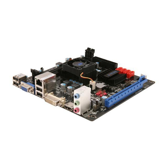
Page 8: Mainboard Layout
E350 Mainboard 1-3 Mainboard Layout The following figure shows the location of components on the mainboard. See following page for description. ~ 4 ~... - Page 9 E350 Mainboard Item Component description AMD E350 APU AMD Hudson-M1 (A50M) Chip DDR3 SO-DIMM Slots 1-2 PCI-E x16 Slot (supports x4 bandwidth) Mini PCI-E Slot 24-Pin ATX Power Connector 4-pin ATX_12V Power Connector Mainboard Battery PC Speaker SATA III Connectors *5 Front Panel Header USB2.0 Header *4...
- Page 10 E350 Mainboard I/O Back Panel The I/O back panel for this mainboard is shown below. When installing the mainboard into the computer case, use the bundled I/O shield to protect this back panel. USB 2.0 Ports (Four) The mainboard provides an OHCI (Open Host Controller Interface) Universal Serial Bus root for attaching USB devices such as a keyboard, mouse or other USB-compatible devices.
- Page 11 E350 Mainboard USB 3.0 ports (Two) USB 3.0 ports are backwardly compatible with USB 2.0 devices. Supports data transfer rates up to 4.8Gb/s (SuperSpeed). D-Sub Port The D-Sub female port provides connection to analogue VGA monitors. DVI-D Port The DVI-D (Digital Visual Interface-Digital) port provides a high-speed digital interconnection between the computer and its display device.
-
Page 12: Chapter 2 Installation
E350 Mainboard Chapter 2 Installation 2-1 Before You Begin Please take note of all precautions before you install anything on to the mainboard or change any of the mainboard settings. Turn off the power to your system and discharge your body’s static electric charge by touching a grounded surface—for example, the metal surface of the... -
Page 13: Installing System Memory
E350 Mainboard 2-4 Installing System Memory This mainboard has two 204-pin SO-DIMM sockets for DDR3 memory. Supports 1GB, 2GB and 4GB DDR3 SO-DIMMs. Supports 1.5v DDR3-1066/800 SO-DIMMs with single channel architecture Memory configurations: To use 1 DIMM: Install into either DIMM slot 1 or slot 2. -
Page 14: Installing Expansion Cards
E350 Mainboard 2-5 Installing Expansion Cards The mainboard provides one PCI Express 2.0 x16 slot and one mini PCI-E slot. Mini PCI-E slot (with x1 link, Black) PCI-E2.0 x16 slot (with x4 link, Blue) PCI-E Slot The design of this motherboard supports PCI-E Express x16 card complying with the PCI Express specification. -
Page 15: Connecting Cables
E350 Mainboard 2-6 Connecting Cables This section takes you through all the necessary connections on the mainboard. Connecting Power Supply Cables 24-pin ATX Power PW2 is the main power supply connector. Make sure that the power supply cable and pins are properly aligned with the connector on the mainboard. Firmly plug the power supply cable into the connector and make sure it is secure. -
Page 16: Connecting To The Internal Headers And Connectors
E350 Mainboard Connecting to the Internal Headers and Connectors Front Panel Header The front panel header on this motherboard is one connector used to connect the front panel switches and LEDs. PWR_LED Attach the front panel power LED cable to these two pins of the connector. -
Page 17: Usb Header
E350 Mainboard USB Header This mainboard contains four (4) USB 2.0 ports that are exposed on the rear panel of the chassis. This mainboard also contains two 10-pin internal header connectors onboard that can be used to connect an optional external bracket containing four (4) USB 2.0 ports. -
Page 18: Com1 (Serial Port Header)
E350 Mainboard COM1 (Serial Port Header) The COM header can provide one serial port via an optional COM port cable. Fan Header There are two fan headers (CPUFAN, PWRFAN) on the motherboard. They can be speed detected/controlled and displayed in the Hardware Health Configuration section of the CMOS Setup. -
Page 19: Jumper Settings
E350 Mainboard 2-7 Jumper Settings If the CMOS data becomes corrupted or you forgot the supervisor or user password, clear the CMOS data to reconfigure the system back to the default values stored in the ROM BIOS. To clear CMOS data, please follow the steps below. -
Page 20: Chapter 3 Configuring The Bios
E350 Mainboard Chapter 3 Configuring the BIOS This chapter provides information on the BIOS Setup program and allows you to configure the system for optimum use. 3-1 Enter BIOS Setup The BIOS is the communication bridge between hardware and software. -
Page 21: Main Menu
E350 Mainboard 3-2 Main Menu When entering the Aptio Setup Utility, the main menu screen appears. This main menu includes the system overview and displays the basic system configuration, such as BIOS information, memory size and system date/time. Aptio Setup Utility - Copyright (C) 2010 American Megatrends, Inc. -
Page 22: Advanced Menu
E350 Mainboard 3-3 Advanced Menu The Advanced menu items allow you to change the settings for the CPU, USB and other system devices. Press <Enter> to display the configuration options. Aptio Setup Utility - Copyright (C) 2010 American Megatrends, Inc. -
Page 23: Pci Subsystem Settings
E350 Mainboard PCI Subsystem Settings Aptio Setup Utility - Copyright (C) 2010 American Megatrends, Inc. Advanced Enables or Disables PCI Express PCI Express Device Settings Device Relaxed ordering. Relaxed Ordering [Disabled] Extended Tag [Disabled] No Snoop [Enabled] Maximum Payload [Auto]... -
Page 24: Acpi Settings
E350 Mainboard ASPM Support Sets the ASPM level, select “Force L0” can force all links to L0 state. Options: Disabled, Auto, Force L0. Extended Synch If select “Enabled”, allows generation of Extended Synchronization patterns. Options: Enabled, Disabled. ACPI Settings Aptio Setup Utility - Copyright (C) 2010 American Megatrends, Inc. -
Page 25: Cpu Configuration
E350 Mainboard CPU Configuration Aptio Setup Utility - Copyright (C) 2010 American Megatrends, Inc. Advanced CPU Configuration Disabled for Windows XP. Limit CPUID Maximum [Disabled] PSS Support [Enabled] PSTATE Adjustment [PState 0] PPC Adjustment [PState 0] NX Mode [Enabled] SVM Mode... -
Page 26: Ide Configuration
E350 Mainboard C6 Mode Allows you to select C6 State for Nehalem processor. Options: Enabled, Disabled. Node 0 Information Displays the Node 0 Information. IDE Configuration Aptio Setup Utility - Copyright (C) 2010 American Megatrends, Inc. Advanced IDE Configuration SATA Port0... -
Page 27: Usb Configuration
E350 Mainboard USB Configuration Aptio Setup Utility - Copyright (C) 2010 American Megatrends, Inc. Advanced USB Configuration Enables Legacy USB support; AUTO option disables legacy USB Devices: support if no USB devices are 1 Keyboard, 1 Mouse connected, DISABLED option... -
Page 28: Super Io Configuration
E350 Mainboard USB transfer time-out The time-out value for control, bulk, and interrupt transfers. Options: 1 sec, 5 sec, 10 sec, 20 sec. Device reset time-out Sets USB mass storage devices start unit command time-out. Options: 10 sec, 20 sec, 30 sec, 40 sec. -
Page 29: H/W Monitor
E350 Mainboard H/W Monitor Aptio Setup Utility - Copyright (C) 2010 American Megatrends, Inc. Advanced PC Health Status Fan Mode Setting. CPU Temperature : +45 C System Temperature : +27 C CPU Fan Speed : 8021 RPM System Fan Speed... -
Page 30: Onboard Device
E350 Mainboard Onboard Device Aptio Setup Utility - Copyright (C) 2010 American Megatrends, Inc. Advanced Bluetooth [Enabled] Marvell 88E8057 Gigabit Lan [Enabled] NEC USB 3.0 Controller [Enabled] MiniPCIE Slot [Enabled] HD Audio Azalia Device [Enabled] : Select Screen Select Item... -
Page 31: Chipset Menu
E350 Mainboard 3-4 Chipset Menu The chipset menu items allow you to change the advanced chipset settings. Press <Enter> to display the sub-menu. Aptio Setup Utility - Copyright (C) 2010 American Megatrends, Inc. Main Advanced Boot Boot Security Save & Exit... - Page 32 E350 Mainboard IOMMU Mode IOMMU is supported on LINUX based system to convert 32bit I/O to 64bit MMIO. Options: Disabled, 32MB, 64MB, 128MB, 256MB, 512MB, 1GB, 2GB. Memory Clock Allows you to select different memory clock. Options: Auto, 400MHz, 533MHz.
-
Page 33: South Bridge
E350 Mainboard South Bridge Aptio Setup Utility - Copyright (C) 2010 American Megatrends, Inc. Security Chipset SB CIM Version : 1.1.0.5 Options for SATA Configuration SB SATA Configuration SB USB Configuration : Select Screen Select Item Enter: Select +/-: Change Opt. -
Page 34: Amd Power Express Configuration
E350 Mainboard AMD Power Express Configuration Aptio Setup Utility - Copyright (C) 2010 American Megatrends, Inc. Security Chipset Enable one of the special AMD AMD Power Express Configuration graphics features (if supported) such as PowerXpress: Discrete Gfx Special Graphics Features... -
Page 35: Boot Menu
E350 Mainboard 3-5 Boot Menu The Boot menu is used to configure the boot settings and the boot priority. Aptio Setup Utility - Copyright (C) 2010 American Megatrends, Inc. Main Advanced Chipset Boot Security Save & Exit Boot Boot Configuration... -
Page 36: Security Menu
E350 Mainboard Interrupt 19 Capture Allows specify if legacy PCI option ROMs are allowed to capture software interrupt 19h. Options: Enabled, Disabled. Boot Option #1/#2 These options are used to form the boot order and are dynamically generated. 3-6 Security Menu The Security menu allows you to change the system security settings. -
Page 37: Save & Exit Menu
E350 Mainboard 3-7 Save & Exit Menu The Save & Exit menu allows you to load the optimal default values for BIOS, and save or discard your changes to the BIOS items. Aptio Setup Utility - Copyright (C) 2010 American Megatrends, Inc. - Page 38 E350 Mainboard Save as User Defaults This is used to save all current settings as user default. The current setup state can later be restored using Restore User Defaults. Restore User Defaults This is used to restore all tokens to settings previously stored by Save as User Defaults.
-
Page 39: Chapter 4 Driver Installation
E350 Mainboard Chapter 4 Driver Installation After the operating system has been installed, you need to install drivers for this mainboard. The support CD that came with the motherboard contains necessary drivers and useful utilities that enhance the motherboard features. -
Page 40: Chapter 5 Post Code
E350 Mainboard Chapter 5 POST Code This chapter provides the Aptio POST Codes List for the mainboard during the BIOS pre-boot process. The POST Codes are displayed on the Debug LED readout located directly onboard the mainboard. Please refer to following “boot phases”, which may apply to various status code &... -
Page 41: Pei Phase
E350 Mainboard OEM initialization before microcode loading Microcode loading AP initialization after microcode loading North Bridge initialization after microcode loading South Bridge initialization after microcode loading OEM initialization after microcode loading Cache initialization SEC Error Codes 0C – 0D Reserved for future AMI SEC error codes... - Page 42 E350 Mainboard Post-Memory South Bridge initialization is started Post-Memory South Bridge initialization (South Bridge module specific) Post-Memory South Bridge initialization (South Bridge module specific) Post-Memory South Bridge initialization (South Bridge module specific) 3F-4E OEM post memory initialization codes DXE IPL is started PEI Error Codes Memory initialization error.
-
Page 43: Dxe Phase
E350 Mainboard DXE Phase Status Code Description DXE Core is started NVRAM initialization Installation of the South Bridge Runtime Services CPU DXE initialization is started CPU DXE initialization (CPU module specific) CPU DXE initialization (CPU module specific) CPU DXE initialization (CPU module specific) - Page 44 E350 Mainboard IDE initialization is started IDE Reset IDE Detect IDE Enable SCSI initialization is started SCSI Reset SCSI Detect SCSI Enable Setup Verifying Password Start of Setup Reserved for ASL (see ASL Status Codes section below) Setup Input Wait...
Need help?
Do you have a question about the Pure Fusion Mini E350 and is the answer not in the manual?
Questions and answers