Table of Contents
Advertisement
Federal Communications Commission (FCC) Statement
This equipment has been tested and found to comply with the limits for a Class B digital
device, pursuant to Part 15 of FCC Rules. These limits are designed to provide reasonable
protection against harmful interference in a residential installation. This equipment
generates, uses and can radiate radio frequency energy and, if not installed and used in
accordance with instructions contained in this manual, may cause harmful interference
to radio and television communications. However, there is no guarantee that interference
will not occur in a particular installation.
If this equipment does cause harmful interference to radio or television reception, which
can be determined by turning the equipment off and on, the user is encouraged to try to
correct the interference by one or more of the following measures:
- REORIENT OR RELOCATE THE RECEIVING ANTENNA
- INCREASE THE SEPARATION BETWEEN THE EQUIPMENT AND THE
RECEIVER
- CONNECT THE EQUIPMENT INTO AN OUTLET ON A CIRCUIT DIFFERENT
FROM THAT OF THE RECEIVER
- CONSULT THE DEALER OR AN EXPERIENCED AUDIO/TELEVISION
TECHNICIAN
NOTE: Connecting this device to peripheral devices that do not comply with Class B
requirements, or using an unshielded peripheral data cable, could also result in
harmful interference to radio or television reception.
The user is cautioned that any changes or modifications not expressly approved
by the party responsible for compliance could void the user's authority to operate
this equipment.
To ensure that the use of this product does not contribute to interference, it is
necessary to use shielded I/O cables.
Copyright
This manual is copyrighted with all rights reserved. No portion of this manual may be
copied or reproduced by any means.
While every precaution has been taken in the preparation of this manual, no responsibility
for errors or omissions is assumed. Neither is any liability assumed for damages resulting
from the use of the information contained herein.
Trademarks
All brand names, logos and registered trademarks mentioned are property of their
respective owners.
Electronic Emission Notices
1
Advertisement
Table of Contents

Related Manuals for Sapphire Audio PC-AM2RX780


Summary of Contents for Sapphire Audio PC-AM2RX780
-
Page 1: Electronic Emission Notices
Electronic Emission Notices Federal Communications Commission (FCC) Statement This equipment has been tested and found to comply with the limits for a Class B digital device, pursuant to Part 15 of FCC Rules. These limits are designed to provide reasonable protection against harmful interference in a residential installation. -
Page 2: Table Of Contents
Sapphire PC-AM2RX780 Motherboard Cable for ATA 133 IDE Sapphire Driver CD for Motherboard and Utilities Cable for Serial ATA II Sappphire PC-AM2RX780 Motherboard User’s Manual Rear External I/O Shield PCI-E X16 slot Switch Card Environmental Protection Announcement Do not dispose this electronic device into the trash while discarding. To minimize pollution... -
Page 3: Features Of Motherboard
Features of motherboard The AMD 770 Series motherboards are based on the latest AMD 770 Chipset and the SB600 chipset which supports the new generation innovative 64-bit AMD Socket AM2+ dual core multi-tasking Socket AM2+ Athlon64 X2 processors. With an integrated low-latency high-bandwidth DDRII memory controller and a highly-scalable Hyper Transport technology-based system bus up to HTT 3.0 . -
Page 4: Special Features Of Motherboard
Special Features of Motherboard CPU Thermal Throttling Technology ---(The CPU Overheat Protection Technology) To prevent the increasing heat from damage of CPU or accidental shutdown while at high workload, the CPU Thermal Throttling Technology will force CPU to enter partially idle mode from 87.5% to 12.5% according to preset CPU operating temperature in BIOS (from 40 ℃... -
Page 5: Specification
Specification Spec Description ∗ Design ATX form factor 4 layers PCB size: 30.5cm*22.0cm Chipset AMD 770 North Bridge Chipset AMD SB600 South Bridge Chipset ∗ Support 64bit AMD Athlon64 940-Pin package utilizes Flip-Chip Pin Grid Array package processor ∗ Support for future AMD Athlon64 940-pin Dual –Core CPU Socket AM2+ Athlon 64x2 processor, Athlon 64 &... -
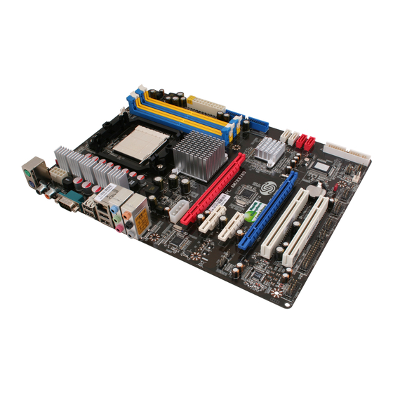
Page 6: Layout Diagram & Jumper Setting
Layout Diagram & Jumper Setting RJ45 LAN Line-IN USB1 Surrback Coaxial In/Out Line-OUT PS/2 Mouse CEN/LFE PS/2 Keyboard Surround MIC-IN COM Connector KB/MS Power On Jumper(JP1) ATX 12V Power Connector CPU FAN PS2 KB/Mouse Port Coaxial In/Out CPU Socket AM2+ DDR2 Socket x 4 COM Connector USB Port... -
Page 7: Expansion Sockets
Jumpers Jumper Name Description Page JBAT CMOS RAM Clear 3-pin Block Keyboard/USB Power On Enabled/Disabled 3-pin Block Connectors Connector Name Description Page ATX Power Connector 24-pin Block P.13 ATXPWR ATX12V ATX 12V Power Connector 8-pin Block P.13 PS2 KB/MS PS/2 Mouse & PS/2 Keyboard Connector 6-pin Female P.14 UL1for USB... -
Page 8: Hardware Installation
Hardware Installation Hardware installation Steps Before using your computer, you had better complete the following steps: 1. Check motherboard jumper setting 2. Install CPU and Fan 3. Install System Memory (DIMM) 4. Install Expansion cards 5. Connect IDE and Front Panel /Back Panel cable 6. -
Page 9: Install Cpu
(2) Keyboard function Enabled/Disabled: JP1 Install CPU About AMD Athlon64 Socket AM2 CPU This motherboard provides a 940-pin surface mount, Zero Insertion Force (ZIF) socket, referred to as the mPGA940 socket supports AMD Athlon64 processor in the 940 Pin package utilizes Flip-Chip Pin Grid Array package technology. -
Page 10: Install Memory
Install Memory This motherboard provides four 240-pin DDR2 DUAL INLINE MEMORY MODULES (DIMM) sockets for DDR2 memory expansion available from minimum memory volume of 128MB to maximum memory volume of 4.0GB DDR SDRAM. Valid Memory Configurations Bank 240-Pin DIMM Total Memory Bank 0, 1 (DIMM1) DDR2 533/DDR2 667/DDR2 800 128MB∼2.0GB Bank 2, 3 (DIMM2) DDR2 533/DDR2 667/DDR2 800... -
Page 11: Expansion Cards
Expansion Cards WARNING! Turn off your power when adding or removing expansion cards or other system components. Failure to do so may cause severe damage to both your motherboard and expansion cards. Procedure For Expansion Card Installation 1. Read the documentation for your expansion card and make any necessary hardware or software setting for your expansion card such as jumpers. -
Page 12: Pci Express Slot
IMPORTANT! If using PCI cards on shared slots, make sure that the drivers support “Shared IRQ” or that the cards don’t need IRQ assignments. Conflicts will arise between the two PCI groups that will make the system unstable or cards inoperable. PCI Express Slot Two PCI-Express2.0 x16 graphics slot offers 8Gbyte/sec data transfer rate at each relative direction. -
Page 13: Connectors
Connectors, Headers & Jumper Setting Connectors Power Connector (24-pin block) : ATXPWR ATX Power Supply connector. This is a new defined 24-pins connector that usually comes with ATX case. The ATX Power Supply allows to use soft power on momentary switch that connect from the front panel switch to 2-pins Power On jumper pole on the motherboard. - Page 14 (3) PS/2 Mouse & PS/2 Keyboard Connector: KB The connectors are for PS/2 keyboard and PS/2 Mouse. (4) USB Port connector: USB4 The connectors are 4-pin connectors that connect USB devices to the system board. (5) LAN Port connector: UL1 This connector is standard RJ45 connector for Network The USBLAN1 support 10M/100Mb/1000Mb s data transfer rate Audio Line-In, Lin-Out, MIC Connector : CN2,CN3...
-
Page 15: Headers
IDE1 Pin 1 Primary IDE Connector • Two hard disks can be connected to each connector. The first HDD is referred to as the “Master” and the second HDD is referred to as the “Slave”. • For performance issues, we strongly suggest you don’t install a CD-ROM or DVD-ROM drive on the same IDE channel as a hard disk. - Page 16 These headers are used for connecting the additional USB port plug. By attaching an option USB cable, your can be provided with two additional USB plugs affixed to the back panel. USB3 USB2 USB1 Pin 1 Pin 1 Pin 1 USB Port Headers (3) Speaker connector: SPEAK This 4-pin connector connects to the case-mounted speaker.
- Page 17 CPUFAN SYSFAN1 SYSFAN2 FAN Power Headers (9) CD Audio-In Headers (4-pin) : CDIN CDIN are the connectors for CD-Audio Input signal. Please connect it to CD-ROM CD-Audio output connector. C DIN CD Audio-In Headers (10) IR infrared module Headers (5-pin) : IR This connector supports the optional wireless transmitting and receiving infrared module.
- Page 18 Pin 1 PARALLEL Header (13) HDMI-SPDIF The SPDIF output is capable of providing digital audio to external speakers or compressed AC3 data to an external Dolby digital decoder. Use this feature only when your stereo system has digital input function. Use SPDIF IN feature only when your device has digital output function.
-
Page 19: Starting Up Your Computer
Starting Up Your Computer 1. After all connection are made, close your computer case cover. 2. Be sure all the switch are off, and check that the power supply input voltage is set to proper position, usually in-put voltage is 220V∼240V or 110V∼120V depending on your country’s voltage used. -
Page 20: Useful Setup
Useful Setup BIOS Setup The BIOS is a program located on a Flash Memory on the motherboard. This program is a bridge between motherboard and operating system. When you start the computer, the BIOS program gain control. The BIOS first operates an auto-diagnostic test called POST (power on self test) for all the necessary hardware, it detects the entire hardware device and configures the parameters of the hardware synchronization. -
Page 21: The Main Menu
The Main Menu Once you enter Award ® BIOS CMOS Setup Utility, the Main Menu (Figure 3-1) will appear on the screen. The Main Menu allows you to select from fourteen setup functions and two exit choices. Use arrow keys to select among the items and press <Enter> to accept or enter the sub-menu. -
Page 22: Standard Cmos Features
Password Setting This entry for setting Supervisor password and User password Save & Exit Setup Save CMOS value changes to CMOS and exit setup. Exit Without Saving Abandon all CMOS value changes and exit setup. Standard CMOS Features The items in Standard CMOS Setup Menu are divided into several categories. Each category includes no, one or more than one setup items. -
Page 23: Advanced Bios Features
If you select Manual, related information is asked to be entered to the following items. Enter the information directly from the keyboard. This information should be provided in the documentation from your hard disk vendor or the system manufacturer. If the controller of HDD interface is SCSI, the selection shall be “None”. If the controller of HDD interface is CD-ROM, the selection shall be “None”... - Page 24 The default value is Enabled. Enabled (default) Enable cache Disabled Disable cache Note: The internal cache is built in the processor. External Cache Choose Enabled or Disabled. This option enables the Level 2 cache memory. Quick Power On Self-Test This category speeds up Power On Self Test (POST) after you power on the computer. If this is set to Enabled.
-
Page 25: Advanced Chipset Features
MPS Version Control For OS This option is only valid for multiprocessor motherboards as it specifies the version of the Multiprocessor Specification (MPS) that the motherboard will use. OS Select For DRAM > 64MB Allows OS2® to be used with >64MB or DRAM. Settings are Non-OS/2 (default) and OS2. Set to OS/2 if using more than 64MB and running OS/2®. -
Page 26: Dram Configuration
DRAM Configuration Phoenix – AwardBIOS CMOS Setup Utility DRAM Configuration DRAM Latency (tcl) Auto Item Help RAS to RAS R/W Delay (tRTC) Auto Row precharge Time (tRP) Auto Minium RAS Active Time (Tras) Auto Menu Level >> DRAM Command Rate CKE base Power down Mode Disabled CKE based powerdom... -
Page 27: Pcie Configuration
HT Link Control Phoenix – AwardBIOS CMOS Setup Utility HT link Control HT link Width Auto Item Help HT link Frequency Auto IH Flow Control Mode Disabled HT link Trislate Disabled Menu Level > 2x LCLK Mode Disabled Unit ID Clumping Disabled ↑↓→←... - Page 28 Super IO Function Setup Phoenix – AwardBIOS CMOS Setup Utility Super IO Function Setup Power on By Mouse Disabled Power on by keyboard Disabled Onboard FDC Controller Enabled Onboard Serial Port1 3F8/IRQ4 Menu Level >> UART Mode Select Disabled Onboard Parallel Port 378/IRQ7 Parallel Port Mode *ECP Mode Use DMA...
-
Page 29: Onchip Ide Function
simultaneously. The ECP mode has to use the DMA channel, so choose the onboard parallel port with the ECP feature. After selecting it, the following message will appear: “ECP Mode Use DMA” at this time, the user can choose between DMA channels 3 to 1. The onboard parallel port is EPP Spec. -
Page 30: Power Management Setup
Onchip PCI Device Phoenix – AwardBIOS CMOS Setup Utility OnChip PCI Device Onboard LAN Device Enabled Item Help Onboard Lan Boot Rom Disabled HD Audio Auto Onchip USB Controller Enabled Menu Level >> USB EHCI Controller Enabled USB Keyboard Support Enabled USB Printer Compability Enabled... - Page 31 ACPI Function This item allows you to Enabled/Disabled the Advanced Configuration and Power Management (ACPI). The settings are Enabled and Disabled. HDD Power Down (Disabled) The IDE hard drive will spin down if it is not accessed within a specified length of time.Options are from 1 Min to 15 Min and Disable.
-
Page 32: Pc Health Status
Reset Configuration Data If you enable this item and restart the system, any Plug and Play configuration data stored in the BIOS Setup is cleared from memory. Init Display First Use this item to specify whether your graphics adapter is installed in one of the PCI E slots or is integrated on the motherboard. - Page 33 will works over 60% of full speed, and the higher temperature will gain higher FAN speed, after over the temperature which this item setting, the FAN works in full speed. CPU Idle Temp This item allows you setting the FAN works in 60% of full speed, when the temperature lower than the temperature which you setting.
-
Page 34: Cpu Vcore
Phoenix – AwardBIOS CMOS Setup Utility Power User Overclock Settings CPU Vcore 7-Shift CPU/HT Reference Clk(MHz) Item Help PCIE Reference clock Normal... [ ] SB Reference clock AMD CPU Ratio Control Auto +5% .... .[ ] Menu Level > Memory Clock Mode Auto +10% .... - Page 35 NB Voltage This item allows you to select value of Voltage for North Bridge Chipset. Phoenix – AwardBIOS CMOS Setup Utility Power User Overclock Settings VDIMM Select CPU/HT Reference Clk(MHz) Item Help PCIE Reference clock ……… SB Reference clock AMD CPU Ratio Control Auto 1.70v Menu Level >...
- Page 36 Phoenix – AwardBIOS CMOS Setup Utility Power User Overclock Settings AMD CPU Ratio Control CPU/HT Reference Clk(MHz) Item Help PCIE Reference clock Auto ... SB Reference clock AMD CPU Ratio Control Auto ... [ ] X4.. Menu Level > Memory Clock Mode Auto X4.5........
-
Page 37: Load Optimized Defaults
CPU Thermal –throttling Phoenix – AwardBIOS CMOS Setup Utility CPU Themal-Throttling CPU Thermal –Throttling Disabled *CPU TThermal-Throttling Item Help Menu Thermal Throttling Temp Min=40 Max=90 Key in a DEC number ↑↓:Move ENTER:Accept ESC:Abort Level >> ↑↓→← Move Enter:Select +/-/PU/PD:Value F10:Save ESC:Exit F1:General Help F5:Previous Values F6:Fail-safe Defaults F7:Optimized Defaults... -
Page 38: Password Settings
Password Settings You can set either supervisor or user password, or both of them. The differences are: Supervisor password: Can enter and change the options of the setup menus. User password: Can only enter but do not have the right to change the options of the setup menus. -
Page 39: Driver & Free Program Installation
DRIVER & FREE PROGRAM INSTALLATION Check your package and there is A MAGIC INSTALL CD included. This CD consists of all DRIVERS you need and some free application programs and utility programs. In addition, this CD also include an auto detect software which can tell you which hardware is installed, and which DRIVERS needed so that your system can function properly. - Page 40 8. BROWSE CD to browse the contents of the CD 9. EXIT to exit from MAGIC INSTALL menu Install ATI Intergrated Driver Pack 2. Click Next when ATI software driver pack 1. Click ATI in the MAGIC INSTALL MENU appears. appears.
- Page 41 3. Click FINISH and restart your computer 4. Manual Sound Effect Setting 5. Drivers and mixer. 6. Audio input and output settings . 7. Microphone effect. 8. 3D Audio NOTE: Please upgrade your Windows XP to Service Pack 1 / Windows 2000 to Service Pack 4 or later before you the HD Audio CODEC driver.
-
Page 42: Install Realtek Lan Controller Driver
Install Realtek LAN Controller Driver 1. Click LAN when Magic Install Menu appear 2. Click Install to install REALTEK LAN and Fast Ethernet NIC Driver 3. To click “yes” to accept the license agreement 4.Click install 5. Installing proseces 6.After driver installation completed, click finish... - Page 43 Install ATI USB2.0 DRIVER Windows 2000 OS Please install Windows 2000 service pack 4 or later . Windows XP OS Please install Windows XP service pack 1 or later . Install RAID SATA Driver and Utility 1 Click RAIDDisk when MAGIC INSTALL 2.
- Page 44 PC-CILLIN Install PC-CILLIN 2007 Anti-virus program Click PC-CILLIN when MAGIC INSTALL Please select “Install program” when the MENU appears "Trend Micro internet security" install shield wizard windows appears This is license agreement, select "I accept the The scanning process terms in the licence agreement" and Click NEXT Click Next after you select the features you 6.Click Install after you select to install the...
- Page 45 7. copying new files 8. click “automatically restart your computer now ”and Finish to activate this function. Install MyGuard Hardware monitor Utility 1. Click PC-health when MAGIC INSTALL 2. Click Next on My Guard Install Shield Wizard MENU appears Window 3.
- Page 46 AMD Platform RAID Function Installation Step 1. Please get into the location: BIOS setup \ Integrated Peripherals \ Onchip IDE function \ Onchip SATA Type ,choose RAID to enable the RAID function and choose the RAID hard drive channel. Phoenix – AwardBIOS CMOS Setup Utility RAID Configuration RAID Enable Enabled...
- Page 47 Step 3. Making RAID driver diskette before Install WindowsXP/2000 Before you install the Windows XP or Windows 2000, you will need to make a RAID driver diskette before you start to install the Operating System. How to make a RAID driver diskette? 1: Insert the diskette which is being formatted in floppy drive on a system which can start OS.
-
Page 48: Pro Magic Plus Function Introduction
Pro Magic Plus Function Introduction What’s Pro Magic Plus? Tired with reinstall OS each time when it doesn’t work? Does your computer often crash down or unable to work after installed new software? Have you had great loses and troubles because of computer problems? Still using time-consuming backup software that occupies lots of HD space? Pro Magic Plus- an instant system recovery software tailored to solve these problems for you. - Page 49 NOTE: Functions of each version will differ from each other, and will be based on the function descriptions of each version. System Requirements ◇ First OS must be Windows 98 SE/ME/2000/XP ◇ Support Only Windows OS (No Linux) ◇ Windows server OS and Windows NT not supported ◇...
-
Page 50: Useful Help
USEFUL HELP HOW TO UPDATE BIOS Before updating the BIOS, users have to “Disable” the “Flash Part Write Protect” selection in “Miscellaneous Control” of BIOS SETUP. Otherwise the system the will not allow you to upgrade BIOS by Award Flash Utility. STEP 1. - Page 51 Glossary Chipset (or core logic) - two or more integrated circuits which control the interfaces between the system processor, RAM, I/O devises, and adapter cards. Processor slot/socket - the slot or socket used to mount the system processor on the motherboard.
Need help?
Do you have a question about the PC-AM2RX780 and is the answer not in the manual?
Questions and answers