Table of Contents
Advertisement
Advertisement
Table of Contents

Related Manuals for Sapphire Audio PB-CI7S41X58


Summary of Contents for Sapphire Audio PB-CI7S41X58
- Page 1 User’s Manual Sapphire Pure Black X58 PB-CI7S41X58 Intel X58/LGA1366 Series Mainboard TRADEMARK All products and company names are trademarks or registered trademarks of their respective holders. These specifications are subject to change without notice. Manual Revision 1.0 October 28, 2010...
- Page 2 PB-CI7S41X58 Mainboard Federal Communications Commission (FCC) Statement This device has been tested and found to comply with the limits for a Class B digital device, pursuant to Part 15 of FCC Rules. These limits are designed to provide reasonable protection against harmful interference in a residential installation.
-
Page 3: Table Of Contents
PB-CI7S41X58 Mainboard Table of Contents Chapter 1 Introduction ................. 1 1-1 Mainboard Specifications ................1 1-2 Package Contents ..................3 1-3 Mainboard Layout ..................4 I/O Back Panel ..................6 Chapter 2 Installation ................8 2-1 Before You Begin ..................8 2-2 Installing the I/O Shield ................ - Page 4 PB-CI7S41X58 Mainboard 3-1 Enter BIOS Setup ..................22 3-2 Main Menu ....................23 3-3 Performance Menu .................. 24 CPU Configuration .................. 26 Memory Timing Configuration ..............28 Voltage Configuration ................30 3-4 Advanced Menu..................32 IDE Configuration ..................33 Hardware Health Configuration ..............34 USB Configuration ..................
-
Page 5: Chapter 1 Introduction
PB-CI7S41X58 Mainboard Chapter 1 Introduction 1-1Mainboard Specifications ® Supports Intel Core i7 series processor in the LGA1366 package Chipset ® Intel X58 and ICH10R chipset System Memory Six 240-pin DDR3 SDRAM DIMM sockets Supports 1.5v DDR3-1066/1333+ DIMMs with triple channel architecture ... -
Page 6: Onboard Audio
PB-CI7S41X58 Mainboard Onboard IEEE1394a (Firewire) Two IEEE1394a ports (one at rear panel, one onboard by header) with 400 Mbps transfer rate Onboard Audio Supports 8-channel High-Definition audio Supports rear panel SPDIF, Coaxial output Supports Jack-detection function Expansion Slots ... -
Page 7: Package Contents
PB-CI7S41X58 Mainboard 1-2Package Contents Your Sapphire Pure Black X58 mainboard comes with the following accessories. 1. Mainboard 2. Quick Installation Guide 3. Driver CD 4. I/O Shield 5. SATA Data Cable *6 6. IDE Cable ~ 3 ~... -
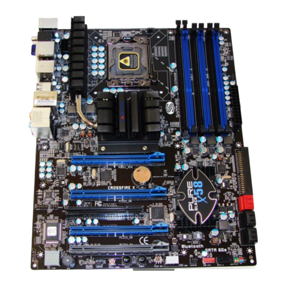
Page 8: Mainboard Layout
PB-CI7S41X58 Mainboard 1-3Mainboard Layout The following figure shows the location of components on the mainboard. See Page 5 for the Key ~ 4 ~... - Page 9 PB-CI7S41X58 Mainboard Item Component description CPU Socket 1366 Intel X58 Chipset Intel ICH10R Chipset DDR3 DIMM Slots 1-6 24-Pin ATX Power Connector 8-pin ATX_12V Power Connector PCI-E x16 Slots1-4 PCI Slot IDE Connector SATA3 Connectors *2 SATA2 Connectors *5 Front Panel Header...
-
Page 10: I/O Back Panel
PB-CI7S41X58 Mainboard I/O Back Panel The I/O back panel for this mainboard is shown below. When installing the mainboard into the computer case, use the bundled I/O shield to protect this back panel. PS/2 Keyboard/Mouse Port This connector is used for a keyboard or mouse. You can plug a PS/2 keyboard or mouse directly into this connector. -
Page 11: Audio Ports
PB-CI7S41X58 Mainboard ESATA Port The ESATA (External SATA) port provides connection to ESATA hard drives. IEE1394a (Firewire) Port The IEEE 1394 port provides connection to IEEE 1394 devices. LAN Ports with LEDs The mainboard provides one standard RJ-45 jack for connecting to a Local Area Network (LAN). -
Page 12: Chapter 2 Installation
PB-CI7S41X58 Mainboard Chapter 2 Installation 2-1 Before You Begin Please take note of all precautions before you install anything on to the mainboard or change any of the mainboard settings. Turn off the power to your system and discharge your body’s static electric charge by touching a grounded surface—for example, the metal surface of the... -
Page 13: Installing The Cpu And Fan Heatsink
PB-CI7S41X58 Mainboard 2-4 Installing the CPU and Fan Heatsink To install the CPU :- Open the socket lever by pushing the lever down and away from the socket. Remove the protective socket cover from the socket. Do not touch the socket contacts. -
Page 14: Installing System Memory
PB-CI7S41X58 Mainboard 2-5 Installing System Memory This mainboard has six 240-pin DIMM sockets for DDR3 memory. These slots support 1GB, 2GB and 4GB DDR3 DIMMs. Make sure that you install memory modules of the same type and density in different channel DIMM slots for Triple-Channel/Dual-Channel mode. -
Page 15: Memory Installation
PB-CI7S41X58 Mainboard Memory Installation: DDR3 and DDR2 memory modules are physically different. Please only install DDR3 DIMMs in this mainboard. To make sure you have the correct DIMM, check that all the notches line up with the DDR3 DIMM slot. -
Page 16: Installing Expansion Cards
PB-CI7S41X58 Mainboard 2-6 Installing Expansion Cards The mainboard provides four PCI Express 2.0 x16 slots and one PCI slot. PCIE1_X16 PCI-E2.0 x16 slot (with x16 link, Blue) PCIE2_X8 PCI-E2.0 x16 slot (with x8 link, Blue) PCI slot (Black) PCIE3_X8 PCI-E2.0 x16 slot (with x8 link, Blue) PCIE4_X4 PCI-E1.0 x16 slot (with x4 link, Gray) -
Page 17: Pci Slot
PB-CI7S41X58 Mainboard PCI Slot The one PCI slot provided supports a variety of expansion cards such as a LAN card, USB card, SCSI card and other cards that comply with PCI specifications. When installing a card into the PCI slot, be sure that it is fully seated. Secure the card’s metal bracket to the chassis back panel. -
Page 18: Connecting Ide Cables
PB-CI7S41X58 Mainboard Connecting IDE Cables The IDE connector supports Ultra ATA 133/100 IDE hard/optical disk drives. 1. Connect one end of the cable (single connector) to the mainboard. 2. Connect another connector on the cable to the Ultra ATA master device. -
Page 19: Connecting To The Internal Headers And Connectors
PB-CI7S41X58 Mainboard Connecting to the Internal Headers and Connectors Front Panel Header The front panel header on this motherboard is one connector used to connect the front panel switches and LEDs. PWR_LED Attach the front panel power LED cable to these two pins of the connector. - Page 20 PB-CI7S41X58 Mainboard USB Header This mainboard contains eight (8) USB 2.0 ports that are exposed on the rear panel of the chassis. This mainboard also contains one 10-pin internal header connectors onboard that can be used to connect an optional external bracket containing two (2) USB 2.0 ports.
- Page 21 PB-CI7S41X58 Mainboard CFPA Header This header allows you to connect the front panel audio. The audio connector supports HD audio standard. S/PDIF Header This header is used to connect S/PDIF (Sony & Philips Digital Interconnect Format) interface for digital audio transmission.
-
Page 22: Fan Header
PB-CI7S41X58 Mainboard Fan Header There are six fan headers (CPUFAN, SYSFAN, SYSFAN1, PWRFAN, CHAFAN, AUXFAN) on the motherboard. Three of these fans (CPUFAN, PWRFAN, CHAFAN) can be speed detected/controlled and displayed in the Hardware Health Configuration section of the CMOS Setup. The fans are automatically turned off after the system enters S3, S4 or S5 mode. -
Page 23: Diagnostics Led
PB-CI7S41X58 Mainboard 2-8 Diagnostics LED This mainboard provides a two-digit POST code to show why the system may be failing to boot. It is useful during a troubleshooting situation. This Debug LED will also display the current CPU temperature after the system has fully booted into the operating system. -
Page 24: Onboard Buttons
PB-CI7S41X58 Mainboard 2-10 Onboard Buttons These onboard buttons include Clear CMOS, RESET and POWER, which allow you to easily clear the CMOS, reset the system and turn on/off the system. Clear CMOS Button The mainboard uses the CMOS RAM to store some of the system configuration. -
Page 25: Dual Bios Switched Jumper
PB-CI7S41X58 Mainboard 2-11 Dual BIOS Switched Jumper This mainboard includes two onboard BIOS, (Primary and Secondary BIOS), to support the Dual BIOS functionality which is set by on board jumper. When the primary BIOS is corrupted or failed, you can use the secondary BIOS to take over on the next system boot to ensure normal system operation. -
Page 26: Chapter 3 Configuring The Bios
PB-CI7S41X58 Mainboard Chapter 3 Configuring the BIOS This chapter provides information on the BIOS Setup program and allows you to configure the system for optimum use. 3-1 Enter BIOS Setup The BIOS is the communication bridge between hardware and software. -
Page 27: Main Menu
PB-CI7S41X58 Mainboard 3-2 Main Menu When entering the BIOS SETUP UTILITY, the main menu screen appears. This main menu includes the system overview and displays the basic system configuration, such as BIOS ID, CPU name, memory size and system date/time. -
Page 28: Performance Menu
PB-CI7S41X58 Mainboard 3-3 Performance Menu The Performance menu is used to configure the frequency and voltage for CPU and memory. BIOS SETUP BIOS SETUP UTILITY UTILITY Main Advanced PCIPnP Boot Security Exit Performanc Frequency & Voltage Configuration Configure CPU. Manufacturer: Intel Intel (R) Xeon (R) CPU X5680 @ 3.33GHz... - Page 29 PB-CI7S41X58 Mainboard Memory Timing Allows you to select the Memory Timing. Options: Auto, By DRAM Ratio, By DDR-800, By DDR-1067, By DDR-1333, By DDR-1600, By DDR-1867. CPU Uncore Frequency (Mhz) Allows you to select the CPU Uncore Frequency, the Uncore clock must be at least 2x DRAM clock for overclocking.
-
Page 30: Cpu Configuration
PB-CI7S41X58 Mainboard CPU Configuration BIOS SETUP UTILITY Main Advanced PCIPnP Boot Security Exit Performance Configure advanced CPU settings Configure CPU. Module version: 01.0C CPU Revision Manufacturer: Intel Intel (R) Xeon (R) CPU X5680 @ 3.33GHz Frequency :3.33GHz BCLK Speed :133MHz... - Page 31 PB-CI7S41X58 Mainboard Execute-Disable Bit Capability When this function is disabled, it forces the XD feature flag to always return to zero (0). Options: Enabled, Disabled. Intel (R) HT Technology ® Allows you to enable the Intel HT (Hyper-Threading) Technology. Options: Enabled, Disabled.
-
Page 32: Memory Timing Configuration
PB-CI7S41X58 Mainboard C1 Auto Demotion When enabled, CPU will conditionally demote C3/C6/C7 requests to C1 based on uncore auto-demote information. Options: Enabled, Disabled C3 Auto Demotion When enabled, CPU will conditionally demote C6/C7 requests to C3 based on uncore auto-demote information. - Page 33 PB-CI7S41X58 Mainboard tRAS Set the minimum RAS# active time. Options: 9 ~ 63, 0 by auto detection. tRFC Set the minimum refresh recovery time. Options: 15 ~ 255, 0 by auto detection. Command Rate Set the command timing setting on a per clock unit basis.
-
Page 34: Voltageconfiguration
PB-CI7S41X58 Mainboard VoltageConfiguration BIOS SETUP UTILITY Main Advanced PCIPnP Boot Security Exit Performanc Voltage Configuration Enabled Disabled Loadline Control [Enabled 100%] CPU Thermal [Enabled] Current CPU VCore : 1.18750V CPU VCore : [Auto] Current DIMM Voltage : 1.50V DIMM Voltage... - Page 35 PB-CI7S41X58 Mainboard DIMM Voltage Allows you to adjust the DIMM Slot voltage. Options: 1.10V ~1.50V in 0.05V increments and 1.50V ~ 2.50V in 0.01V increments. Current VTT Displays the current VTTvoltage. CPU VTT Allows you to adjust the CPU VTT voltage.
-
Page 36: Advanced Menu
PB-CI7S41X58 Mainboard DIMM DQ Vref Allows you to adjust the DIMM DQ reference voltage. DQ Vref= DIMM voltage+Offset Options: +480mV ~-490mV in 10mV increments CPU PWM Frequency Allows you to adjust the CPU PWM Frequency Options: 380KHz, 460KHz, 520KHz, 580KHz, 770KHz, 870KHz, 950KHz, 1010KHz. -
Page 37: Ide Configuration
PB-CI7S41X58 Mainboard IDE Configuration BIOS SETUP UTILITY Advanced IDE Configuration Disabled Compatible SATA#1 Configuration [Compatible] Enhanced Configure SATA#1 as [IDE] SATA#2 Configuration [Enhanced] Primary IDE Master : [Hard Disk] Primary IDE Slave : [ATAPI CDROM] Secondary IDE Master : [Not Detected] ... -
Page 38: Hardware Health Configuration
PB-CI7S41X58 Mainboard Primary IDE Master/Primary IDE Slave/Secondary IDE Master/Secondary IDE Slave /Third IDE Master/Fourth IDE Master Sets the IDE configuration for the device that you specify. IDE Detect Time Out (sec) Selects the time out value for detecting IDE devices. -
Page 39: Usb Configuration
PB-CI7S41X58 Mainboard H/W Health Function Enables the onboard hardware monitor to automatically detect and display the CPU and mainboard temperatures. Options: Enabled, Disabled. CPU / VREG / System Displays the current CPU, onboard regulator and system temperature. CPU /Power /Chassis Fan Speed... -
Page 40: Acpi Configuration
PB-CI7S41X58 Mainboard USB Functions Enables the USB controller. Options: Enabled, Disabled. Legacy USB Support Allows you select legacy support for USB devices. Options: Enabled, Disabled, Auto. USB 2.0 Controller Mode Allows you to configure the USB 2.0 Controller Mode. Options: HiSpeed (480Mbps), FullSpeed (12Mbps) -
Page 41: Intel Vt-D Configuration
PB-CI7S41X58 Mainboard USB Device Wakeup From S3 Allows a USB keyboard device to wake-up the system from S3 state. Options: Enabled, Disabled. High Precision Event Timer Allows you to enable or disable the High Precision Event Timer. Options: Enabled, Disabled. - Page 42 PB-CI7S41X58 Mainboard Relaxed Ordering Enables the PCI Express device Relaxed Ordering. Options: Auto, Enabled, Disabled. Maximum Payload Size Sets the Maximum Payload size of PCI Express Device or allows the System BIOS to select the value. Options: Auto, 128 Bytes, 256 Bytes, 512 Bytes, 1024 Bytes, 2048 Bytes, 4096 Bytes.
-
Page 43: Onboarddevice Configuration
PB-CI7S41X58 Mainboard OnboardDevice Configuration BIOS SETUP UTILITY Advanced Onboard Device Settings Enables/Disables PCI Express Device SATA 3.0 Storage Controller [Enabled] Relaxed Ordering. USB 3.0 Controller [Enabled] IEEE1394 Controller [Enabled] HD Audio Controller [Enabled] Marvell 88E8057 Giga LAN [Auto] Select Screen... -
Page 44: Pcipnp Menu
PB-CI7S41X58 Mainboard Restore on AC Power Loss Enables your computer to automatically restart or return to its last operating status after power returns from a power failure. Options: Power off, Power on, Last State. 3-5 PCI PnP Menu The PCI PnP Menu is used to configure the PCI bus and Plug and Play (PnP) settings. -
Page 45: Boot Menu
PB-CI7S41X58 Mainboard 3-6 Boot Menu The Boot menu is used to configure the boot settings and the boot priority. BIOS SETUP UTILITY Main Performance Advanced PCIPnP Security Exit Boot Boot Settings Configure Settings during System Boot. Boot Settings Configuration Boot Device Priority... - Page 46 PB-CI7S41X58 Mainboard Quiet Boot Displays normal POST message. Select disable to display Logo instead of POST message. Options: Enabled, Disabled. Bootup Num-Lock Selects power-on state for Num-Lock. Options: On, Off. PS/2 Mouse Support Selects support for PS/2 mouse. Options: Auto, Enabled, Disabled.
-
Page 47: Security Menu
PB-CI7S41X58 Mainboard 3-7 Security Menu The Security menu allows you to change the system security settings. BIOS SETUP UTILITY Main Performance Advanced PCIPnP Boot Exit Security Security Settings Install or Change the password. Supervisor Password :Not Installed User Password :Not Installed... -
Page 48: Exit Menu
PB-CI7S41X58 Mainboard 3-8 Exit Menu The Exit menu allows you to load the optimal default values for BIOS, and save or discard your changes to the BIOS items. BIOS SETUP UTILITY Main Performance Advanced PCIPnP Boot Security Exit Exit Options... -
Page 49: Chapter 4 Driver Installation
PB-CI7S41X58 Mainboard Chapter 4 Driver Installation After the operating system has been installed, you need to install drivers for this mainboard. The support CD that came with the motherboard contains necessary drivers and useful utilities that enhance the motherboard features. -
Page 50: Trixx Utility
PB-CI7S41X58 Mainboard TRIXX Utility TRIXX is a simple and easy-to-use utility that allows users to adjust system settings for overclocking in a Windows environment. The TRIXX utility includes three configurations for frequency, voltage and hardware monitoring. To install TRIXX Utility, run it from the Sapphire Utility page from the bundled CD. -
Page 51: Chapter 5 Ami Post Code
PB-CI7S41X58 Mainboard Chapter 5 AMI POST Code This chapter provides the AMI POST Codes List for the mainboard during the BIOS pre-boot process. The POST Codes are displayed on the Debug LED readout located directly onboard the mainboard. Code Description... - Page 52 PB-CI7S41X58 Mainboard Display sign-on message Initialize USB controller Initialize DMAC-1 & DMAC-2 Initialize real time clock Test system memory Initialization of chipset registers Detect coprocessor Update CMOS memory size Initialize NUM-LOCK Initialize Int-13 Initialize IPL devices Generate and write contents of ESCD...
Need help?
Do you have a question about the PB-CI7S41X58 and is the answer not in the manual?
Questions and answers