Table of Contents
Advertisement
Advertisement
Table of Contents

Subscribe to Our Youtube Channel
Related Manuals for Sapphire Audio Pure Platinum A75


Summary of Contents for Sapphire Audio Pure Platinum A75
- Page 1 User’s Manual Sapphire Pure Platinum A75 AMD A75 Chipset for FM1 Socket Mainboard TRADEMARK All products and company names are trademarks or registered trademarks of their respective holders. These specifications are subject to change without notice. Manual Revision 1.1 August 18, 2011...
- Page 2 Federal Communications Commission (FCC) Statement This device has been tested and found to comply with the limits for a Class B digital device, pursuant to Part 15 of FCC Rules. These limits are designed to provide reasonable protection against harmful interference in a residential installation.
-
Page 3: Table Of Contents
Table of Contents Chapter 1 Introduction .............. 1 1-1 Mainboard Specifications ............1 1-2 Package Contents ..............4 1-3 Mainboard Layout ..............5 Chapter 2 Installation ..............9 2-1 Before You Begin ............... 9 2-2 Installing the I/O Shield .............. 9 2-3 Securing to the Chassis ............. - Page 4 2-10 Onboard Buttons ..............20 Clear CMOS Button ..............20 Reset and Power Button ............20 2-11 Dual BIOS Switch ..............21 Chapter 3 Configuring the BIOS ..........22 3-1 Select Boot Device ..............22 3-2 Enter BIOS Setup ..............22 3-3 Main Menu ................
-
Page 5: Chapter 1 Introduction
Chapter 1 Introduction 1-1 Mainboard Specifications ® Supports AMD Llano APU with FM1 socket *Please refer to Appendix for supporting APU and Dual Graphics configuration Chipset AMD A75 (Hudson D3) chipset Graphics On-die AMD Radeon HD 6xxx series graphic Three independent display and supporting dual display with HDMI/DVI and HDMI/Display Port Port Supported resolution... - Page 6 SATA Ports Five SATA3 ports with 6Gb/s data transfer rate One E-SATA port at real panel Supports RAID 0, RAID 1 and RAID 10 Supports AHCI (Advanced Host Controller Interface) Onboard LAN One Gigabit Ethernet from Marvell 88E8059 Gigabit controller Bluetooth ®...
- Page 7 1 x Display port 1 x DVI-D port 1 x HDMI port 1 x RJ45 LAN port 2 x USB 3.0 ports 6 audio jacks Internal I/O Connectors 1 x 24-pin ATX power connector 1 x 8-pin ATX 12V power connector 5 x SATA3 connectors 4 x USB2.0 headers 2 x USB3.0 headers...
-
Page 8: Package Contents
1-2 Package Contents Your Sapphire mainboard comes with the following accessories. 1. Mainboard 2. I/O Shield 3. Quick Installation Guide 4. Driver CD 5. USB3.0 Front Panel Cable 6. SATA Data Cable *4 ~ 4 ~... -
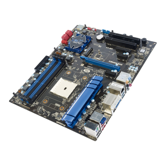
Page 9: Mainboard Layout
1-3 Mainboard Layout The following figure shows the location of components on the mainboard. See following page for description. See next page for details ~ 5 ~... - Page 10 Item Component description AMD CPU Socket FM1 AMD A75 (Hudson D3) Chip DDR3 DIMM Slots 1-4 PCI-E 2.0 x16 Slot *1 PCI-E 2.0 x1 Slot *2 PCI-E 2.0 x4 Slot *1 PCI Slot *2 Mini PCI-E Slot 24-Pin ATX Power Connector 8-pin ATX_12V Power Connector SATA3 Connectors *5 Front Panel Header...
- Page 11 I/O Back Panel The I/O back panel for this mainboard is shown below. When installing the mainboard into the computer case, use the bundled I/O shield to protect this back panel. PS/2 Keyboard/Mouse Port This connector is used for a keyboard or mouse. You can plug a PS/2 keyboard or mouse directly into this connector.
- Page 12 HDMI Port The HDMI (High-Definition Multimedia Interface) provides an all-digital audio/video interface to transmit the uncompressed audio/video signals and is HDCP compliant. Connect the HDMI audio/video device to this port. Dual Display Configurations: This mainboard provides three ports for video output: DVI-D, HDMI and Display port.
-
Page 13: Chapter 2 Installation
Chapter 2 Installation 2-1 Before You Begin Please take note of all precautions before you install anything on to the mainboard or change any of the mainboard settings. Turn off the power to your system and discharge your body’s static electric charge by touching a grounded surface—for example, the metal surface of the power supply—before performing any hardware procedure. -
Page 14: Installing The Cpu And Fan Heatsink
2-4 Installing the CPU and Fan Heatsink Follow the steps below to install the CPU & cooler correctly. 1. Open the socket lever and rise to a 90 degree angle. 2. Align the CPU pin one (small triangle marking) and gently insert the CPU into the socket then close the socket lever. -
Page 15: Installing System Memory
2-5 Installing System Memory This mainboard has four 240-pin DIMM sockets for DDR3 memory. These slots support 1GB, 2GB and 4GB DDR3 DIMMs up to max. 16GB Make sure that you install memory modules of the same type and density in different channel DIMM slots for Dual-Channel mode. -
Page 16: Installing Expansion Cards
2-6 Installing Expansion Cards The mainboard provides one PCI Express 2.0 x16 slot, one PCI Express 2.0 x4 slot, two PCI Express 2.0 x1 slots, one Mini PCI x1 slot and two PCI slots. PCI-E2.0 x1 slot (with x1 link, Black) PCI-E2.0 x16 slot (with x16 link, Blue) Mini PCI-E slot (with x1 link) PCI-E2.0 x1 slot (with x1 link, Black) -
Page 17: Pci Slots
2. Plug the Mini PCI card firmly into the slot at a 45-degree angle until it clicks into place. 3. Secure the Mini PCI-E card with accompanied screws. PCI Slots The two PCI slots provided supports a variety of expansion cards such as a LAN card, USB card, SCSI card and other cards that comply with PCI specifications. -
Page 18: Connecting Serial Ata (Sata) Cables
Connecting Serial ATA (SATA) Cables SATA cables support the Serial ATA protocol. Each cable can be used to connect one internal SATA drive to the mainboard. The S1 to S3 connectors are SATA3 compliant and work at speeds of up to 6 Gb/s. -
Page 19: Connecting To The Internal Headers And Connectors
Connecting to the Internal Headers and Connectors Front Panel Header The front panel header on this motherboard is used to connect the front panel switches and LEDs. PWR_LED Attach the front panel power LED cable to these two pins of the connector. The Power LED indicates the system’s status. -
Page 20: Usb2.0 Headers
USB2.0 Headers This mainboard contains four (4) USB 2.0 ports that are exposed on the rear panel of the chassis. This mainboard also contains two 10-pin onboard header connectors that can be used to connect to four (4) external USB 2.0 devices. Refer to the following steps: 1. -
Page 21: Cfpa Header
CFPA Header This header allows you to connect the front panel audio. The audio connector supports HD audio standard. S/PDIF Header This header is used to connect S/PDIF (Sony & Philips Digital Interconnect Format) interface for digital audio transmission. ~ 17 ~... -
Page 22: Fan Headers
Fan Headers There are six fan headers (CPUFAN, SYSFAN, SYSFAN1, PWRFAN, CHAFAN, AUXFAN) on the motherboard. Three of these fans (CPUFAN, PWRFAN, CHAFAN) can be speed detected/controlled and displayed in the Hardware Health Configuration section of the CMOS Setup. The fans are automatically turned off after the system enters S3, S4 or S5 mode. -
Page 23: Diagnostics Led
2-8 Diagnostics LED This mainboard provides a two-digit POST code to show why the system may be failing to boot. It is useful during a troubleshooting situation. This Debug LED will also display the current CPU temperature after the system has fully booted into the operating system. -
Page 24: Onboard Buttons
2-10 Onboard Buttons These onboard buttons include Clear CMOS, RESET and POWER, which allow you to easily clear the CMOS, reset the system and turn on/off the system. Clear CMOS Button The mainboard uses the CMOS RAM to store some of the system configuration. The CMOS can be cleared by pressing the Clear CMOS button. -
Page 25: Dual Bios Switch
2-11 Dual BIOS Switch This mainboard includes dual onboard BIOS, (Primary and Secondary BIOS), When the primary BIOS is corrupted or has failed, you can use the secondary BIOS to take over on the next system boot to ensure normal system operation. To enable the secondary BIOS, please refer to the following steps: 1. -
Page 26: Chapter 3 Configuring The Bios
Chapter 3 Configuring the BIOS This chapter provides information on the BIOS Setup program and allows you to configure the system for optimum use. 3-1 Select Boot Device Select Boot Device Menu allows you to set the first boot device without entering BIOS Setup. - Page 27 released and may be different from your purchased motherboard. Users are welcome to download the latest BIOS version from our official website ControlKeys Please check the following table for the function description of each Controlkey. Control Key(s) Function Description / Moves cursor left or right to select Screens Moves cursor up or down to select items + / -...
-
Page 28: Main Menu
3-3 Main Menu When entering the Aptio Setup Utility, the main menu screen appears. This main menu includes the system overview and displays the basic system configuration, such as BIOS information, memory size and system date/time. Aptio Setup Utility - Copyright (C) 2011 American Megatrends, Inc. Main Performance Advanced... -
Page 29: Performance Menu
3-4 Performance Menu The Performance menu allows you to specify your settings for CPU, memory, voltage control and overclocking. Press <Enter> to display the configuration options. Aptio Setup Utility - Copyright (C) 2011 American Megatrends, Inc. Main Advanced Chipset Boot Security Save &... -
Page 30: Memory Configuration
Memory Configuration Aptio Setup Utility - Copyright (C) 2011 American Megatrends, Inc. Performance Allows you to select the Memory Multiplier Configuration memory multiplier. Current Multiplier Frequency: Memory Frequency [Auto] Current tCL: CAS# Latency (tCL) [Auto] Current tRCD: RAS# to CAS# Delay(tRCD) [Auto] Current tRP: Row Precharge Time(tRP) - Page 31 RAS# Active Time(tRAS) Set the minimum RAS# active time. Options: Auto, 15 ~ 30. Write Recovery Time(tWR) Set the internal Write to Read recovery time. Options: Auto, 5 ~ 12. Row Refresh Cycle Time(tRFC) Set the minimum refresh recovery time. Options: Auto, 15 ~ 255.
-
Page 32: Voltage Configuration
Voltage Configuration Aptio Setup Utility - Copyright (C) 2011 American Megatrends, Inc. Performance Voltage Configuration [+000mV] APU_NB [+000mV] [1.10V] DIMM DQ Voltage [Auto] DIMM CA Voltage [Auto] VDDR [1.20V] : Select Screen VDDP [1.20V] Select Item VDDA [2.50V] Enter: Select DIMM Voltage [1.50V] +/-:... - Page 33 Options: 1.20V ~1.83V in 0.01V increments. VDDA Allows you to adjust the filtered PLL voltage. Options: 2.50V ~3.31V in 0.01V increments. DIMM Voltage Allows you to adjust the DIMM Slot voltage. Options: Auto, 1.50V ~2.30V in 0.01V increments. DIMM VTT Allows you to adjust the DIMM VTT voltage.
-
Page 34: Advanced Menu
3-5 Advanced Menu The Advanced menu items allow you to change the settings for the CPU, USB and other system devices. Press <Enter> to display the configuration options. Aptio Setup Utility - Copyright (C) 2011 American Megatrends, Inc. Main Performance Chipset Boot Security... -
Page 35: Pci Subsystem Settings
PCI Subsystem Settings Aptio Setup Utility - Copyright (C) 2011 American Megatrends, Inc. Advanced PCI Bus Driver Version V 2.04.00 In case of multiple Option ROMs (Legacy and EFI PCI Option ROM Handling Compatible), specifies what PCI ROM Priority [EFI Compatible ROM] PCI Option ROM to launch. - Page 36 PCI Express Settings Advanced Enables or disables PCI PCI Express Device Register Settings Express Device Relaxed Relaxed Ordering [Disabled] Ordering. Extended Tag [Disabled] No Snoop [Enabled] Maximum Payload [Auto] Maximum Read Request [Auto] PCI Express Link Register Settings ASPM Support [Disabled] : Select Screen ...
- Page 37 Options: Disabled, Auto, Force L0. Extended Synch If select “Enabled”, allows generation of Extended Synchronization patterns. Options: Enabled, Disabled. Link Training Retry Defines number of Retry attempts software will take to retrain the link if previous training attempt was unsuccessful. Options: Disabled, 2, 3, 5.
-
Page 38: Acpi Settings
ACPI Settings Aptio Setup Utility - Copyright (C) 2011 American Megatrends, Inc. Advanced ACPI Settings EuP Function [Disabled] Enable ACPI Auto Configuration [Disabled] Enable Hibernation [Enabled] ACPI Sleep State [S3 (Suspend to RAM)] : Select Screen Lock Legacy Resources [Disabled] Select Item Enter: Select... -
Page 39: Cpu Configuration
CPU Configuration Aptio Setup Utility - Copyright (C) 2011 American Megatrends, Inc. Advanced CPU Configuration Number of cores to enable in each processor package. Limit CPUID Maximum [Disabled] C6 Mode [Disabled] AMD PowerOn Function [Enabled] [Enabled] Node 0 Information : Select Screen ... -
Page 40: Ide Configuration
Node 0 Information Displays current processor information. Aptio Setup Utility - Copyright (C) 2010 American Megatrends, Inc. Advanced Node0: AMD E2-3200 APU with Radeon(TM) HD Graphics Dual Core Running @ 2433 MHz 1362 mV Max Speed:2400 MHz Intended Speed:2400 MHz Microcode Patch Level: 300000f --Information de cachette par noyau –... -
Page 41: Usb Configuration
USB Configuration Aptio Setup Utility - Copyright (C) 2011 American Megatrends, Inc. Advanced USB Configuration Enables Legacy USB support; AUTO option disables legacy USB Devices: support if no USB devices are 1 Keyboard, 1 Mouse connected, DISABLED option will keep USB devices Legacy USB Support [Enabled] available only for EFI... -
Page 42: H/W Monitor
Device reset time-out Sets USB mass storage devices start unit command time-out. Options: 10 sec, 20 sec, 30 sec, 40 sec. Device power-up delay Maximum time the device will take before it properly reports itself to the Host controller. ‘Auto’ uses default values; for a Root port it is 100ms, for a Hub port the delay is taken from Hub descriptor. - Page 43 CPU / VREG / System Displays the current CPU, onboard regulator and system temperature. CPU /Power /Chassis Fan Speed Displays the current CPU, Power and Chassis Fan Speed VCC3V/APU/APU_NB/FCH/DIMM/APU_VDDR/APU_VDDP/VSB3V/VBAT The current voltages are automatically detected and displayed by the system. CPU Fan Type Allows you to select the CPU Fan type.
-
Page 44: Onboard Device
Onboard Device Aptio Setup Utility - Copyright (C) 2011 American Megatrends, Inc. Advanced Onboard Device PCIE1x1 Slot [Enabled] PCIE3x1 Slot [Enabled] Marvell 88E8059 [Enabled] Mini PCIE Slot [Enabled] HD Audio Azaila Device [Enabled] C80P Show CPU Temperature [Enabled] : Select Screen ... -
Page 45: Chipset Menu
3-6 Chipset Menu The chipset menu items allow you to change the advanced chipset settings. Press <Enter> to display the sub-menu. Aptio Setup Utility - Copyright (C) 2011 American Megatrends, Inc. Main Performance Advanced Boot Boot Security Save & Exit Chipset North Bridge South Bridge... - Page 46 Memory Configuration Aptio Setup Utility - Copyright (C) 2011 American Megatrends, Inc. Security Chipset Enable Integrate Graphics Memory Configuration controller Integrated Graphics [Auto] Memory Hole Remapping [Enabled] Bank Interleaving [Enabled] Channel Interleaving [Enabled] : Select Screen Select Item Enter: Select +/-: Change Opt.
-
Page 47: South Bridge
Node 0 Information This filed displays the memory information related to Mode 0. Aptio Setup Utility - Copyright (C) 2010 American Megatrends, Inc. Chipset Socket 0 Information Starting Address: 0 KB Ending Address: 167777215 KB Dimm0: size=4906 MB, Speed=1333 MHz Dimm0: size=4906 MB, Speed=1333 MHz Dimm0: size=4906 MB, Speed=1333 MHz Dimm0: size=4906 MB, Speed=1333 MHz... - Page 48 SB SATA Configuration Aptio Setup Utility - Copyright (C) 2011 American Megatrends, Inc. Chipset OnChip SATA Channel [Enabled] OnChip SATA Type [AHCI] SATA IDE Combined Mode [Disabled] : Select Screen Select Item Enter: Select +/-: Change Opt. General Help Previous Values Optimized Defaults Save and Exit...
- Page 49 SB USB Configuration This filed for USB ports Configuration. Aptio Setup Utility - Copyright (C) 2011 American Megatrends, Inc. Chipset XHCI Switch [Enabled] OHCI HC(Bus 0 Dec 18 Fn 0) [Enabled] EHCI HC(Bus 0 Dec 18 Fn 2) [Enabled] OHCI HC(Bus 0 Dec 19 Fn 0) [Enabled] EHCI HC(Bus 0 Dec 19 Fn 2) [Enabled]...
-
Page 50: Boot Menu
3-7 Boot Menu The Boot menu is used to configure the boot settings and the boot priority. Aptio Setup Utility - Copyright (C) 2011 American Megatrends, Inc. Main Performance Advanced Chipset Boot Security Save & Exit Boot Boot Configuration Number of seconds to wait for Setup Prompt Timeout setup activation key. - Page 51 Interrupt 19 Capture Allows specify if legacy PCI option ROMs are allowed to capture software interrupt 19h. Options: Enabled, Disabled. Boot Option #1/#2 These options are used to form the boot order and are dynamically generated. CD/DVD ROM Drive BBS Priorities Allows configure the boot order for a specific CD/DVD ROM device class.
-
Page 52: Security Menu
3-8 Security Menu The Security menu allows you to change the system security settings. Aptio Setup Utility - Copyright (C) 2011 American Megatrends, Inc. Main Performance Advanced Chipset Boot Save & Exit Security Password Description Set setup Administrator Password. If ONLY the Administrator’s password is set, then this only limits access to Setup and is only asked for when entering Setup. -
Page 53: Save & Exit Menu
3-9 Save & Exit Menu The Save & Exit menu allows you to load the optimal default values for BIOS, and save or discard your changes to the BIOS items. Aptio Setup Utility - Copyright (C) 2011 American Megatrends, Inc. Main Advanced Chipset... - Page 54 Save as User Defaults This is used to save all current settings as user default. The current setup state can later be restored using Restore User Defaults. Restore User Defaults This is used to restore all tokens to settings previously stored by Save as User Defaults.
-
Page 55: Chapter 4 Driver Installation
Chapter 4 Driver Installation After the operating system has been installed, you need to install drivers for this mainboard. The support CD that came with the motherboard contains necessary drivers and useful utilities that enhance the motherboard features. 4-1 Driver Install Insert the bundled driver CD into your optical drive and the main menu will... -
Page 56: Trixx Utility
4-2 TRIXX Utility TRIXX is a simple and easy-to-use utility that allows users to adjust system settings for overclocking in a Windows environment. The TRIXX utility includes three configurations for frequency, voltage and hardware monitoring. To install TRIXX Utility, run it from the Sapphire Utility page from the bundled DVD. -
Page 57: Hardware Monitor Gadget
4-3 Hardware monitor gadget This Hardware monitor gadget directly appears in windows screen after TriXX installation is completed. It can be used to help keep track of temperatures of CPU, System and fan speed of CPU, System and voltages of CPU, System. Displays hardware monitor temperature. -
Page 58: Chapter 5 Post Code
Chapter 5 POST Code This chapter provides the Aptio POST Codes List for the mainboard during the BIOS pre-boot process. The POST Codes are displayed on the Debug LED readout located directly onboard the mainboard. Please refer to following “boot phases”, which may apply to various status code &... - Page 59 Microcode loading AP initialization after microcode loading North Bridge initialization after microcode loading South Bridge initialization after microcode loading OEM initialization after microcode loading Cache initialization SEC Error Codes 0C – 0D Reserved for future AMI SEC error codes Microcode not found Microcode not loaded PEI Phase Status Code...
- Page 60 Post-Memory South Bridge initialization (South Bridge module specific) Post-Memory South Bridge initialization (South Bridge module specific) 3F-4E OEM post memory initialization codes DXE IPL is started PEI Error Codes Memory initialization error. Invalid memory type or incompatible memory speed Memory initialization error. SPD reading has failed Memory initialization error.
- Page 61 DXE Phase Status Code Description DXE Core is started NVRAM initialization Installation of the South Bridge Runtime Services CPU DXE initialization is started CPU DXE initialization (CPU module specific) CPU DXE initialization (CPU module specific) CPU DXE initialization (CPU module specific) CPU DXE initialization (CPU module specific) PCI host bridge initialization North Bridge DXE initialization is started...
- Page 62 IDE Reset IDE Detect IDE Enable SCSI initialization is started SCSI Reset SCSI Detect SCSI Enable Setup Verifying Password Start of Setup Reserved for ASL (see ASL Status Codes section below) Setup Input Wait Reserved for ASL (see ASL Status Codes section below) Ready To Boot event Legacy Boot event Exit Boot Services event...
-
Page 63: Chapter 6 Appendix
Chapter 6 Appendix APU and Dual Graphics configuration: Supporting APU Specification: Radeon Radeon DDR3 Dual Turbo Model Brand cores Cores Clock freq. Graphics Core AMD A-series Processors HD65xx 65, 100 W 594MHz 1866 UVD3 HD65xx 65, 100 W 443MHz 1866 UVD3 HD64xx 65 W...
Need help?
Do you have a question about the Pure Platinum A75 and is the answer not in the manual?
Questions and answers