Table of Contents
Advertisement
Advertisement
Table of Contents

Related Manuals for Sapphire Audio PURE CrossFireX 890GX


Summary of Contents for Sapphire Audio PURE CrossFireX 890GX
- Page 1 Sapphire PURE CrossFireX 890GX Motherboard User Manual...
-
Page 2: Electronic Emission Notices
Electronic Emission Notices Federal Communications Commission (FCC) Statement This equipment has been tested and found to comply with the limits for a Class B digital device, pursuant to Part 15 of FCC Rules. These limits are designed to provide reasonable protection against harmful interference in a residential installation. - Page 3 Box Included Checklist Sapphire PC-AM3RS890G Motherboard Cable for ATA 133 IDE Sapphire Driver CD for Motherboard and Utilities Cable for Serial ATA II and Power cable Sappphire PC-AM3RS890G Motherboard User‟s Manual Rear External I/O Shield ...
- Page 4 Environmental Safety Instruction Avoid the dusty, humidity and temperature extremes. Do not place the product in any area where it may become wet. 0 to 40 centigrade is the suitable temperature. (The figure comes from the request of the main chipset) ...
-
Page 5: Table Of Contents
TABLE OF CONTENT INTRODUCTION FEATURES OF MOTHERBOARD ..................1 SPECIAL FEATURES OF MOTHERBOARD ..............2 SPECIFIC A TION ........................3 LAYOUT DIAGRAM ......................4 HARDWARE INSTALLATION INSTALL CPU ........................7 INSTALL MEMORY ......................9 EXPANSION CARDS ......................10 CONNCTORS, HEADERS & JUMPERS SETTING CONNECTORS ........................ -
Page 6: Introduction
Introduction Features of motherboard The AMD 890GX chipset motherboard series are based on the latest AMD 890GX Chipset and the SB 850 chipset which supports: Phenom™ II X 4, Phenom™ II X3 , Phenom™ II X2 processor; Athlon™ II X4; Athlon™ II X3; Athlon™ II X2 processor and Sempron AM3 CPU under 140 power consumption. -
Page 7: Special Features Of Motherboard
designed for power user to use the over-clocking function in more flexible ways. But please be caution that the over-clocking maybe causes the fails in system reliabilities. This motherboard provides the guaranteed performance and meets the demands of the next generation computing. But if you insist to gain more system performance with variety possibilities of the components you choose, please be careful and make sure to read the detailed descriptions of these value added product features, please get them in the coming section. -
Page 8: Specification
Specification Spec Description Design ATX form factor 4 layers PCB size: 30.5cm x24.5cm AMD 890GX North Bridge Chipset Chipset AMD SB 850 South Bridge Chipset Support AMD AM3 CPU : Phenom™ II X 4, Phenom™ II X3 , Phenom™... -
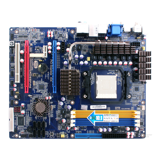
Page 9: Layout Diagram
Layout Diagram Rear I / O for HA09 RJ-45 ESATA Line-IN Coaxial Connector Connector RS-OUT SPDIF_OUT Connector Connector HDMI PS/2 Mouse Line-OUT Connector CS-OUT Port PS/2 Keyboard Port SS-OUT MIC-IN Optical SPDIF_OUT Connector USB Connectors Connector G.P.I. LED KBMB/USB Power On(JP3) CPUFAN SYSFAN2 PS2 KB/Mouse Port... -
Page 10: Expansion Sockets
Jumpers Jumper Name Description JP1/JP2 USB Power On Enabled/Disabled 3-pin Block KB/USB Power On Enabled/Disabled 3-pin Block JBAT Clear CMOS Header 2-pin Block Connectors Connector Name Description ATXPWR1 ATX Power Connector 24-pin Block ATX12V ATX 12V Power Connector 8-pin Block Power Connector 4-Pin Block PS/2 Mouse &... -
Page 11: Hardware Installation
Hardware Installation WARNING! Turn off your power when adding or removing expansion cards or other system components. Failure to do so may cause severe damage to both your motherboard and expansion cards. Hardware installation Steps Before using your computer, you had better complete the following steps: 1. -
Page 12: Install Cpu
(3) CMOS RAM Clear (2-pin): JBAT A battery must be used to retain the motherboard configuration in CMOS RAM short 1-2 pins of JBAT to clear the CMOS data. WARNNING:Please remove or turn off the power supply before CMOS clear! To clear the CMOS, follow the procedure below: Turn off the system and unplug the AC power Remove ATX power cable from ATX power connector... -
Page 13: Cooling Solutions
below. The notched corner should point toward the end of the level. Because the CPU has a corner pin for two of the four corners, the CPU will only fit in the orientation as shown. C o l d e n A r r o w C P U Z I F m P G A B S o c k e t When you put the CPU into the ZIF socket, No force required to insert of the CPU, and then press the level to locate position slightly without any extra force. -
Page 14: Install Memory
Install Memory This motherboard provides four 240-pin DDR III DUAL INLINE MEMORY MODULES (DIMM) socket for DDR III memory expansion available to maximum memory volume of 8GB DDRIII SDRAM. Valid Memory Configurations Bank 240-Pin DIMM PCS Maximum Capacity Bank 0, 1 (DIMM1) DDR III 1066/ DDR III1333 Bank 2, 3 (DIMM2) DDR III 1066/ DDR III1333... -
Page 15: Expansion Cards
Expansion Cards WARNING! Turn off your power when adding or removing expansion cards or other system components. Failure to do so may cause severe damage to both your motherboard and expansion cards. Procedure for Expansion Card Installation 1. Read the documentation for your expansion card and make any necessary hardware or software setting for your expansion card such as jumpers. - Page 16 If using PCI cards on shared slots, make sure that the drivers support “Shared NOTE! IRQ” or that the cards don‟t need IRQ assignments. Conflicts will arise between the two PCI groups that will make the system unstable or cards inoperable. PCI Express2.0 Slots AMD 890GX Series motherboard series offer two PCI-Express 2.0x1 6@ 8 lanes graphics slots.
-
Page 17: Connectors
Connectors and Headers Connectors Power Connector (24-pin block) : ATXPWR1 ATX Power Supply connector: This is a new defined 24-pins connector that usually comes with ATX case. The ATX Power Supply allows using soft power on momentary switch that connect from the front panel switch to 2-pins Power On jumper pole on the motherboard. - Page 18 direction is wrong it is hard to fit in and if you make the connection by force if is possible. Figure1:20-pin power plug Figure 2:24-pin power plug (2)ATX 12V Power Connector (8-pin block) : ATX12V1 This is a new defined 8-pins connector that usually comes with ATX Power Supply.
- Page 19 RJ-45 ESATA Line-IN Coaxial Connector Connector RS-OUT SPDIF_OUT Connector Connector HDMI PS/2 Mouse Line-OUT Connector CS-OUT Port PS/2 Keyboard SS-OUT Port MIC-IN Optical USB Connectors SPDIF_OUT Connector Connector (7) Large 4-Pin Power Connector :J2 Power Connector The connectors are 4-pin connector that supports extra 12V / 5V power to your system (8) Floppy drive Connector (34-pin block): FDD This connector supports the provided floppy drive ribbon cable.
- Page 20 IDE1 Pin 1 IDE Connector Two hard disks can be connected to each connector. The first HDD is referred to as the “Master” and the second HDD is referred to as the “Slave”. For performance issues, we strongly suggest you don‟t install a CD-ROM or DVD-ROM drive on the same IDE channel as a hard disk.
-
Page 21: Headers
The SPDIF output is capable of providing digital audio to external speakers or compressed AC3 data to an external Dolby digital decoder. Use this feature only when your stereo system has digital input function. SPDIF_OUT1(above) is coaxial SPDIF_OUT connector while SPDIF_OUT2(below) optical SPDIF_OUT connector. - Page 22 The Power LED is light on while the system power is on. Connect the Power LED from the system case to this pin. (5) Hard disk Activity LED: HD LED This connector connects to the hard disk activity indicator light on the case. (6) Reset switch lead: RESET This 2-pin connector connects to the case-mounted reset switch for rebooting your computer without having to turn off your power switch.
- Page 23 C D I N C D A u d i o -I n H e a d e r s (10) IR infrared module Headers (5-pin): IR This connector supports the optional wireless transmitting and receiving infrared module. You must configure the setting through the BIOS setup to use the IR function.
-
Page 24: Starting Up Your Computer
HDMI_SPDIF_OUT HDMI_SPDIF Header Starting Up Your Computer 1. After all connections are made, close your computer case cover. 2. Be sure all the switch are off, and check that the power supply input voltage is set to proper position, usually in-put voltage is 220V240V or 110V120V depending on your country‟s voltage used. -
Page 25: Useful Setup
6. During power-on, press <Delete> key to enter BIOS setup. Follow the instructions in BIOS SETUP. 7. Power off your computer: You must first exit or shut down your operating system before switch off the power switch. For ATX power supply, you can press ATX power switching after exiting or shutting down your operating system. -
Page 26: Entering Setup
Press Enter to go to sub screen. Entering Setup Power on the computer and by pressing <Del> immediately allows you to enter Setup. If the message disappears before your respond and you still wish to enter Setup, restart the system to try again by turning it OFF then ON or pressing the “RESET” button on the system case. -
Page 27: Standard Bios Features
Advanced BIOS Features Use this menu to set the Advanced Features available on your system. Advanced Chipset Features Use this menu to change the values in the chipset registers and optimize your system‟s performance. Integrated Peripherals Use this menu to specify your settings for integrated peripherals. Power Management Features Use this menu to specify your settings for power management. -
Page 28: Advanced Bios Feature
Language Use this item to select the current default language used in BIOS. The Optional settings are: Chinese (GB): English. System Date The date format is <day><month><date><year>. Day of the week, from Sun to Sat, determined by BIOS. Read-only. Month The month from Jan. -
Page 29: Advanced Chipset Features
Quick Boot Allows BIOS to skip certain tests while booting. This will decrease the needed to boot the system. Boot Device Specify the boot sequence from the available devices. A device enclosed in parenthesis has been disabled in corresponding type menu. Boot Up NumLock Status The default value is On. -
Page 30: Onboard Vga Configuration
HDMI Audio Use this item to select HDMI audio, the optional settings are: Enabled, Disabled. NB Power Management Features Dynamic clock gating for IOC/NT/MCU/CFG. Primary Video Controller This item is for user to choose primary video controller. Onboard VGA Configuration Internal Graphics Mode The optional settings: Disabled;... -
Page 31: Pci Express Configuration
SIDEPORT Clock Speed The optional settings are from 200MHz to 667MHz. GFX Engine Clock Override The optional settings are: Enable; Disabled. GFX Engine Clock Use this item to set GFX Engine clock in the range of 150 to 1000. UMA-SP Interleave Mode The optional settings are: Auto, Coarse and Fine. -
Page 32: Power Management Features
OnChip SATA Channel Press Enter to enable or disable CnChip SATA Channel. 0nChip SATA Type Press Enter to select the SATA type. The optional settings are: Native IDE; RAID; AHCI; Legacy IDE. 0nChip IDE Type The optional settings are Legacy IDE and Native IDE. Onboard PCI E Lan Use this item to enable or disable Onboard PCI E Lan. -
Page 33: Miscellaneous Control
Suspend mode Use this item to select the ACPI state used for system suspend. The optional settings are: S1(POS); S3(STR). Power On by PCIE(WOL)/ Keyboard/ Mouse The optional settings are: Enabled; Disabled. Miscellaneous Control Plug &Play O/S The optional settings are: No; Yes No: Let the BIOS configure all the devices in the system. - Page 34 your system has a Plug and Play operating system. PCI Latency Timer Value in units of PCI clocks for PCI device latency timer register. Allocate IRQ for PCI VGA The optional settings are: No; Yes. Yes: Assigns IRQ to PCI VGA card if card requests IRQ. No: Does not assign IRQ to PCI VGA card even card requests an IRQ.
-
Page 35: Smart Fan Configuration
Smart FAN Configuration Temperatue1Limit of Hig/Sec/Thi/Low The setting range is from a Minimum value of 0 C to a maximum value of 127 Fan1 Highest/Second/Third/Fourth/Lowest Setting The setting range is from a Minimum value of 0 to a maximum value of 100. Power User Overclock Setting... - Page 36 CPU/HT Reference Clock Use this item to set CPU/HT Reference Clock. The optional setting range is:190~600 MHz. Processor Frequency Multiplier The optional settings are: Auto and a setting range from x4.0 (800 MHz )to x35.0 (7000 MHz). CPU-NB FID The optional settings are: Auto; x4 ~x31. Link Speed The HyperTransport link will run at this speed if it slower than or equal to system clock and this board is capable...
-
Page 37: Memory Configuration
Warning:Setting some values too high may cause system to malfunction. CPU-NB Voltage 7-Shift Use this item to set value in CPU Vcore 7-Shift function. The optional settings are: Auto; 50mV to 350 mV. NB-Core Voltage Setting The optional settings are from 1.30v to 1.45v. Warning:Setting some values too high may cause system to malfunction. -
Page 38: Bios Security Features
Enable unused clocks to DIMMS when memory slots are not populated. Mem CLK Tristate during C3 and Alt VID. Enable and disable Mem CLK Tri-stating during C3 and Alt VID Memory Hole Remapping Enable Memory Remapping around Memory Hole. DCT Unganged Mode This allows selection of unganged DRAM MODE (64- bit width). - Page 39 and press <Enter>. You may also press <Esc> to abort the selection and not enter a password. To disable a password, just press <Enter> when you are prompted to enter the password. A message will confirm that the password will be disabled. Once the password is disabled, the system will boot and you can enter Setup freely.
- Page 40 Discard Changes and Exit When you press <Enter> on this item, you get a confirmation dialog box with a message similar to: Pressing <OK> to leave BIOS setting without saving previously set values. Notice! The BIOS options in this manual are for reference only. Different configurations may lead to difference in BIOS screen and BIOS screens in manuals are usually the first BIOS version when the board is released and may be different from your purchased motherboard .
-
Page 41: Driver & Free Program Instalation
Driver & Free Program Installation Check your package and there is A MAGIC INSTALL CD included. This CD consists of all DRIVERS you need and some free application programs and utility programs. In addition, this CD also include an auto detect software which can tell you which hardware is installed, and which DRIVERS needed so that your system can function properly. - Page 42 ATI Integrated Drive Pack 1. Click ATI when Magic Install menu appears. 2. Select the setup language then click Next. 3. Click Install to begin installation. 4. Select default installation location then click Next. 5. Click Accept to accept the License 6.
- Page 43 appears. Audio driver windows appear. 3. Click Finish and restart your computer. 4. Manual Sound Effect Setting. 5. mixer setting. 6. Audio input and output setting. 7. Microphone effect setting. 8. 3D demo setting. Install Realtek Gigabit Ethernet NIC Driver 1 Click LAN when Magic Install Menu appears 2.
- Page 44 3 Click install to begin the installation. 2. Installation completed, Click Finish.. Install ATI SATA Driver and Utility 1 Click RAIDDisk when Magic Install menu 2. Copy the files to floppy disk and restart appears the computer with floppy disk as the first booting disk and then follow the steps shown on the screen to finish RAID function settings.
- Page 45 1. Click PC-HEALTH when Magic Install 2. Click Next on Install shield wizard Window menu appears appears 3. Click Install to begin the installation. 4. Click Finish to complete the installation. Install Fusion Drivers and Tools 5. Click Fusion when Magic Install menu 6.
- Page 46 Install HDMI Audio Driver 1. Click HDMI when Magic Install menu 2. Click Next on Install shield wizard Window. appears 3. Select if you want to restart the computer and then click Finish. Install AMD Over-Drive Utility 1. Click OVER CLOCK when Magic Install 2.
- Page 47 3. Choose “I accept the terms in the license 4. The information describes the installation, agreement”. Click Next after you finish reading it. 5. Type in Customer Information and then 6. Select the Destination Folder and then click Next. Click Next. 7.
- Page 48 AMD Platform RAID Function Installation Please set these choice in the BIOS as RAID:BIOS setup \Integrated Peripherals \Onboard SATA Type. When the below figures appeared, please press [Ctrl-F] into figure 2 [figure1] Function: press[1] key, showing the RAID; press [2] key,building RAID; press [3] key, delete the RAID;...
- Page 49 [figure3] Press [2] key, the interface of RAID, as figure 4. RAID function: RAID 1/ RAID 0/ RAID 10 / RAID5/JBOD [figure4] Choose LD 1 then press[Ctrl+C] to building RAID. Take Raid0 for example, use [↑] [↓] to shift the cursor, press space key to change the choice, press [Ctrl-Y] to save.
- Page 50 [figure6] Press [3], delete the RAID mode, as figure 7.press [Delete] will delete the array. As figure 7 . [figure7] Press [4], showing the information of controller, as figure 8. [figure8] Making RAID driver diskette before Install WindowsXP/Vista/7 Before you install the Windows OS, you will need to make a RAID driver diskette before you start to install the Operating System.
-
Page 51: Pro Magic Plus Function Introduction
1: Insert the diskette which is being formatted in floppy drive on a system which can start OS. 2: After booting OS insert the bundle CD in your CD-ROM 3: Copy all the files from\AMD\RAIDDisk to floppy diskette Once you have the SATA driver diskette ready, you may start to install Windows OS on your System. - Page 52 NOTE: Functions of each version will differ from each other, and will be based on the function descriptions of each version. System Requirements ◇ First OS must be Windows XP/Vista/7 ◇ Support Only Windows OS (No Linux) ◇ Windows server OS and Windows NT not supported ◇...
-
Page 53: How To Update Bios
How to Update BIOS Step 1. Prepare a bootable disk. (You may make one by click START click RUN type SYS A: click OK) Step 2. Download upgrade tools and the latest BIOS files of the motherboard from official website and then make a copy of it to your bootable floppy disk after decompressing these files Step 3. -
Page 54: Appendix
Appendix LED Display Function PWS_LED4 PWS_LED3 PWS_LED2 PWS_LED1 All LED off or glitter. It means the motherboard in the G.P.I mode. CPU works with the low power consumption. PWS_LED4 PWS_LED3 PWS_LED2 PWS_LED1 Three LED off or glitter. It means the motherboard is working on partial power saving mode. - Page 55 Regarding the Application of 3-Phase or 3+1 Phase Power Supply Mold As a result of the increasing power consumption demand from many AMD CPUs in current market, we suggest not to use a CPU that demands more than 65W power consumption at work for an AMD CPU compliant board that comes with power supply design as 3 phase or 3+1 phase mold and MOSFET design as working in High SideX1 and Low SideX1 mold so as to avoid MOSFET getting burned or other phenomena like a halted system or system instability.
- Page 56 Suggestion on choosing electric fan Both the amount of electric current to MOSFET and the heat produced from the motherboard go up as AMD‟s CPU power consumption increases. In this case we recommend users select a CPU fan with air outlet towards MOSFET so that CPU fan can carry away heat produced by MOSFET, for better heat dissipation effects.
-
Page 57: Bootblock Initialization Code Checkpoints
Post BIOS Beep Code Number of Beeps Description Memory refresh timer error. Parity error in base memory (first 64KB block) Base memory read/write test error Motherboard timer not operational Processor error 8042 Gate A20 test error (cannot switch to protected mode) General exception error (processor exception interrupt error) Display memory error (system video adapter) AMIBIOS ROM checksum error... -
Page 58: Bootblock Recovery Code Checkpoints
whether to execute serial flash. The Runtime module is uncompressed into memory. CPUID information is stored in memory. Store the Uncompressed pointer for future use in PMM. Copying Main BIOS into memory. Leaves all RAM below 1MB Read-Write including E000 and F000 shadow areas but closing SMRAM. - Page 59 GPNV area. Initialized CMOS as mentioned in the Kernel Variable "wCMOSFlags." Check CMOS diagnostic byte to determine if battery power is OK and CMOS checksum is OK. Verify CMOS checksum manually by reading storage area. If the CMOS checksum is bad, update CMOS with power-on default values and clear passwords.
-
Page 60: Dim Code Checkpoints
Initializes DMAC-1 & DMAC-2. Initialize RTC date/time. Test for total memory installed in the system. Also, Check for DEL or ESC keys to limit memory test. Display total memory in the system. Mid POST initialization of chipset registers. Detect different devices (Parallel ports, serial ports, and coprocessor in CPU, …... -
Page 61: Acpi Runtime Checkpoints
POST to initialize different system busses. The following table describes the main checkpoints where the DIM module is accessed Checkpoint Description Initialize different buses and perform the following functions: Reset, Detect, and Disable (function 0); Static Device Initialization (function 1); Boot Output Device Initialization (function 2). - Page 62 Glossary Chipset (or core logic) - two or more integrated circuits which control the interfaces between the system processor, RAM, I/O devises, and adapter cards. Processor socket - the socket used to mount the system processor on the motherboard. Slot (PCI-E, PCI, RAM) - the slots used to mount adapter cards and system RAM. PCI - Peripheral Component Interconnect - a high speed interface for video cards, sound cards, network interface cards, and modems;...
-
Page 63: Performance List
Performance List The following performance data list is the testing result of some popular benchmark testing programs. These data are just referred by users, and there is no responsibility for different testing data values gotten by users (the different Hardware & Software configuration will result in different benchmark testing results.) Performance Test Report CPU:...
Need help?
Do you have a question about the PURE CrossFireX 890GX and is the answer not in the manual?
Questions and answers