Table of Contents
Advertisement
Federal Communications Commission (FCC) Statement
This equipment has been tested and found to comply with the limits for a Class B digital
device, pursuant to Part 15 of FCC Rules. These limits are designed to provide reasonable
protection against harmful interference in a residential installation. This equipment
generates, uses and can radiate radio frequency energy and, if not installed and used in
accordance with instructions contained in this manual, may cause harmful interference
to radio and television communications. However, there is no guarantee that interference
will not occur in a particular installation.
If this equipment does cause harmful interference to radio or television reception, which
can be determined by turning the equipment off and on, the user is encouraged to try to
correct the interference by one or more of the following measures:
- REORIENT OR RELOCATE THE RECEIVING ANTENNA
- INCREASE THE SEPARATION BETWEEN THE EQUIPMENT AND THE RECEIVER
- CONNECT THE EQUIPMENT INTO AN OUTLET ON A CIRCUIT DIFFERENT FROM
THAT OF THE RECEIVER
- CONSULT THE DEALER OR AN EXPERIENCED AUDIO/TELEVISION TECHNICIAN
NOTE: Connecting this device to peripheral devices that do not comply with Class B
requirements, or using an unshielded peripheral data cable, could also result in
harmful interference to radio or television reception.
The user is cautioned that any changes or modifications not expressly approved
by the party responsible for compliance could void the user‟s authority to operate
this equipment.
To ensure that the use of this product does not contribute to interference, it is
necessary to use shielded I/O cables.
Copyright
This manual is copyrighted with all rights reserved. No portion of this manual may be
copied or reproduced by any means.
While every precaution has been taken in the preparation of this manual, no responsibility
for errors or omissions is assumed. Neither is any liability assumed for damages resulting
from the use of the information contained herein.
Trademarks
All brand names, logos and registered trademarks mentioned are property of their
respective owners.
Electronic Emission Notices
Advertisement
Table of Contents

Subscribe to Our Youtube Channel
Related Manuals for Sapphire Audio PE-AM2RS740G


Summary of Contents for Sapphire Audio PE-AM2RS740G
-
Page 1: Electronic Emission Notices
Electronic Emission Notices Federal Communications Commission (FCC) Statement This equipment has been tested and found to comply with the limits for a Class B digital device, pursuant to Part 15 of FCC Rules. These limits are designed to provide reasonable protection against harmful interference in a residential installation. -
Page 2: Table Of Contents
Cable for Serial ATA II Rear External I/O Shield Sapphire PE-AM2RS740G Motherboard User‟s Manual Environmental Protection Announcement Do not dispose this electronic device into the trash while discarding. To minimize pollution and ensure environment protection of mother earth, please recycle. -
Page 3: Features Of Motherboard
Features of motherboard The AMD 740G Series motherboards are based on the latest AMD740G Chipset and SB700 chipset which supports the new generation innovative 64-bit AMD Socket AM2+ dual core multi-tasking Socket AM2+ Athlon64 X2 processors and dual core AMD Phenom™ processors. -
Page 4: Special Features Of Motherboard
Some special features---CPU Thermal Throttling this motherboard are designed for power user to use the over-clocking function in more flexible ways. But please be caution that the over-clocking maybe cause the fails in system reliabilities. This motherboard provides the guaranteed performance and meets the demands of the next generation computing. -
Page 5: Specification
Specification Spec Description Design Micro u-ATX form factor 4 layers PCB size: 245x200mm Chipset AMD740G Chipset and AMD SB700 Chipset Support 64bit AMD AM2+ 940-Pin package utilizes Flip-Chip Pin Grid CPU Socket AM2+ Array package compatible processor ... -
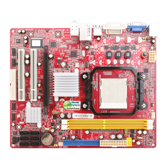
Page 6: Layout Diagram & Jumper Setting
Layout Diagram & Jumper Setting RJ-45 LAN Line-IN DVI Connector PS/2 Mouse Line-OUT PS/2 Keyboard MIC-IN VGA Connector CPU Socket AM2+ CPU FAN ATX 12V Power Connector PS2 KB/Mouse Port Keyboard/USB Power (JP1) Connector DDR2 Socket x2 ATX Power Conn. Connector USB Port RJ-45 Over... -
Page 7: Hardware Installation
Hardware Installation InstallSocket AM2 Supported AMD Processor This motherboard provides a 940-pin surface mount, Zero Insertion Force (ZIF) socket, referred to as the mPGA940 socket supports AMD Athlon64 processor in the 940 Pin package utilizes Flip-Chip Pin Grid Array package technology. The CPU that comes with the motherboard should have a cooling FAN attached to prevent overheating. -
Page 8: Expansion Cards
Figure 2-4 NOTE! When you install DIMM module fully into the DIMM socket the eject tab should be locked into the DIMM module very firmly and fit into its indention on both sides Expansion Cards The motherboards offer one PCI-Express x16by16lane graphics slot of 4Gbyte/sec data transfer rate at each relative direction which gets 3.5 times of bandwidth more than AGP 8X and it‟s up to a peak concurrent bandwidth of 8Gbyte/sec at full speed to guarantee the ultimate GPU computing performance. -
Page 9: Connectors
Connectors, Headers & Jumpers Setting Connectors Power Connector (24-pinblock) ROW1 ROW2 ATXPWR1 ROW1 ROW2 ROW1 ROW2 ATX Power Supply connector: This is a 3.3V 3.3V new defined 24-pins connector that 3.3V -12V usually comes with ATX case. The ATX Soft Power On Power Supply allows using soft power on momentary switch that connect from the front panel switch to 2-pins Power On... - Page 10 RJ-45 LAN Line-IN DVI Connector PS/2 Mouse Line-OUT PS/2 Keyboard MIC-IN VGA Connector (7) Floppy drive Connector (34-pin block): FDD1 This connector supports the provided floppy drive ribbon cable. After connecting the single plug end to motherboard, connect the two plugs at other end to the floppy drives. Pin 1 Floppy Drive Connector (8) (8) Primary IDE Connector (40-pin block): IDE1...
- Page 11 IDE1 IDE1 Pin 1 Primary IDE Connector (9) Serial-ATAII Port connector: SATAII1 / SATAII2 / SATAII3/ SATAII4/ SATAII5/ SATAII6 These connectors support the provided Serial ATA and Serial ATA2 IDE hard disk cable to connecting the motherboard and serial ATA hard disk. SATA6 SATA5 SATA4...
-
Page 12: Headers
Headers (1) Line-Out/MIC Header for Front Panel (9-pin): AUDIO1 These headers connect to Front Panel Line-out, MIC connector with cable. AUDIO Pin 1 Line-Out, MIC Headers (2) USB Port Headers (9-pin) : USB5 / USB6 These headers are used for connecting the additional USB port plug. By attaching an option USB cable, your can be provided with two additional USB plugs affixed to the back panel. - Page 13 (3) Speaker connector: SPEAK1 This 4-pin connector connects to the case-mounted speaker. See the figure below. (4) Power LED: PWR LED1 The Power LED is light on while the system power is on. Connect the Power LED from the system case to this pin. PWRLED Pin 1 JW FP...
- Page 14 (6) CD Audio-In Headers (4-pin) : CDIN CDIN are the connectors for CD-Audio Input signal. Please connect it to CD-ROM CD-Audio output connector. CDIN CD Audio-In Headers (7) Serial COM Port Header: COM1 COM1 is the 9-pin block header. The on-board serial port can be disabled through BIOS SETUP.
-
Page 15: Starting Up Your Computer
Starting Up Your Computer 1. After all connection are made, close your computer case cover. 2. Be sure all the switch are off, and check that the power supply input voltage is set to proper position, usually in-put voltage is 220V240V or 110V120V depending on your country‟s voltage used. -
Page 16: Useful Setup
Useful Setup BIOS Setup The BIOS is a program located on a Flash Memory on the motherboard. This program is a bridge between motherboard and operating system. When you start the computer, the BIOS program gain control. The BIOS first operates an auto-diagnostic test called POST (power on self test) for all the necessary hardware, it detects the entire hardware device and configures the parameters of the hardware synchronization. -
Page 17: The Main Menu
Press F1 to pop up a small help window that describes the appropriate keys to use and the possible selections for the highlighted item. To exit the Help Window, press <Esc>. The Main Menu Once you enter Award BIOS CMOS Setup Utility, the Main Menu (Figure 3-1) will appear on the screen. -
Page 18: Standard Cmos Features
Load Optimized Defaults Use this menu to load the BIOS default values these are setting for optimal performances system operations for performance use. Password Setting This entry for setting Supervisor password and User password Save & Exit Setup Save CMOS value changes to CMOS and exit setup. Exit Without Saving Abandon all CMOS value changes and exit setup. -
Page 19: Advanced Bios Features
properly if you enter improper information for this category. If the type of hard disk drives is not matched or listed, you can use Manual to define your own drive type manually. If you select Manual, related information is asked to be entered to the following items. Enter the information directly from the keyboard. - Page 20 Enabled Activates automatically when the system boots up causing a warning message to appear when anything attempts to access the boot sector of hard disk partition table. CPU Internal Cache The default value is Enabled. Enabled (default) Enable cache Disabled Disable cache Note: The internal cache is built in the processor.
-
Page 21: Advanced Chipset Features
This option allow you to enable the HDD S.M.A.R.T Capability (Self-Monitoring, Analysis and Reporting Technology) . You can choose from Enabled and Disabled. MPS Version Control For OS This option is only valid for multiprocessor motherboards as it specifies the version of the Multiprocessor Specification (MPS) that the motherboard will use. -
Page 22: Dram Configuration
DRAM Configuration Phoenix – AwardBIOS CMOS Setup Utility DRAM Configuration DRAM Latency(tCL) Auto Item Help CKE base Power down Mode Disabled CKE based powerdom per channel Memclock tri-stating Disabled Menu Level >> Memory Hole Remapping Eabled Auto Optimize Bottom IO Enabled *Bottom of {31:24}IO Bottom of UMA DRAM {31:24}... -
Page 23: Pcie Configuration
HT Link Control Phoenix – AwardBIOS CMOS Setup Utility HT link Control HT link Width Auto Item Help HT link Frequency Auto HT Drive Strength Auto Menu Level > HT Drive Strength (P) HT Drive Strength (N) HT Receiver Ctrl Auto ... - Page 24 Super IO Function Setup Phoenix – AwardBIOS CMOS Setup Utility Super IO Function Setup Onboard FDC Controller Enabled Onboard Serial Port1 3F8/IRQ4 UART Mode Select IrDA Onboard Parallel Port 378/IRQ7 Menu Level >> IrDA Duplex Mode Half PWRON After PWR-Fail [OFF] ...
-
Page 25: Onchip Ide Function
“ECP+EPP” will allow the onboard parallel port to support both the ECP and EPP modes simultaneously. The ECP mode has to use the DMA channel, so choose the onboard parallel port with the ECP feature. After selecting it, the following message will appear: “ECP Mode Use DMA”... -
Page 26: Power Management Setup
Onboard Devices Phoenix – AwardBIOS CMOS Setup Utility OnChip PCI Device Onboard PCIE LAN Device Enabled Item Help Onboard PCIE LAN BootROM Disabled HD Audio Azalia Enable Onchip USB Controller Enabled Menu Level >> USB EHCI Controller Enabled USB Keyboard Support Enabled ... - Page 27 Move Enter:Select +/-/PU/PD:Value F10:Save ESC:Exit F1:General Help F5:Previous Values F6:Fail-safe Defaults F7:Optimized Defaults ACPI Function This item allows you to Enabled/Disabled the Advanced Configuration and Power Management (ACPI). The settings are Enabled and Disabled. HDD Power Down (Disabled) The IDE hard drive will spin down if it is not accessed within a specified length of time.Options are from 1 Min to 15 Min and Disable.
-
Page 28: Miscellaneous Control
Miscellaneous Control Phoenix – AwardBIOS CMOS Setup Utility Miscellaneous Control Init Display First PCI Ex Item Help Reset Configuration Data Disabled Resource Controlled by Auto [ESCD] * IRQ Resource Press Enter Menu Level > PCI/VGA Palette Snoop Disabled Assign IRQ for VGA Enabled Assign IRQ for USB Enabled... - Page 29 Phoenix – AwardBIOS CMOS Setup Utility PC Health Status Show PC Health in Post Enabled Item Help Shutdown Temperature Disabled SMART FAN Configuration Press Enter Vcc3.3 3.37v Menu Level > Vcore 1.27V NBVCC 1.08V 5.24V +12V 12.55V 5VSB 5316V VDIMM 1.96V 41 ...
-
Page 30: Power User Overclock Settings
Power User Overclock Settings Phenix – AwardBIOS CMOS Setup Utility Power User Overclock Settings CPU/HT Reference Clk(MHz) PCIE Reference clock Item Help SB Reference clock Spread Spectrum Disabled CPU/HT Reference Clk CPU Ratio at Next Boot Auto NPT Vid control Auto Min=190 AMD K8 Cool&Quiet control... - Page 31 SB Reference clock Phoenix – AwardBIOS CMOS Setup Utility Power User Overclock Settings SB Reference Clock CPU/HT Reference Clk(MHz) Item Help PCIE Reference clock Min = 90 SB Reference clock Max =150 Spread Spectrum Disabled Key in a DEC Number : Menu Level >...
-
Page 32: Load Optimized Defaults
Thermal Throttling Option Phoenix – AwardBIOS CMOS Setup Utility CPU Themal-Throttling CPU Thermal –Throttling Disabled Item Help * Thermal-Throttling Temp 70 ℃ * CPU Thermal-Throttling Duty 50.0% Menu Thermal Throttling Temp Min=40 Max=90 Key in a DEC number :Move ENTER:Accept ESC:Abort Level >>... - Page 33 will appear at the center of the screen to assist you in creating a password. ENTER PASSWORD: Type the password, up to eight characters in length, and press <Enter>. The password typed now will clear any previously entered password from CMOS memory. You will be asked to confirm the password.
-
Page 34: Driver & Free Program Instalation
DRIVER & FREE PROGRAM INSTALLATION Check your package and there is A MAGIC INSTALL CD included. This CD consists of all DRIVERS you need and some free application programs and utility programs. In addition, this CD also include an auto detect software which can tell you which hardware is installed, and which DRIVERS needed so that your system can function properly. - Page 35 Install ATI Intergrated Driver Pack 2. Click Next when ATI software driver pack 1. Click ATI in the DRIVER INSTALL MENU appears. appears. 3. Click “Yes” to accept the license agreement 4. Click Finish to restart your computer and start installation.. Install HD Audio Driver 1.
- Page 36 3. Click FINISH and restart your computer 4. Manual Sound Effect Setting 5. Drivers and mixer. 6. Audio input and output settings . 7. Microphone effect. 8. 3D Audio NOTE: Please upgrade your Windows XP to Service Pack 1 / Windows 2000 to Service Pack 4 or later before you the HD Audio CODEC driver.
- Page 37 Install LAN 1 Click LAN when MAGIC INSTALL MENU 2. Click Next . appears 3 Click Install 2. Finish. Install ATI SATA Driver and Utility 1 Click RAIDDisk when MAGIC INSTALL 2. Install RAID Disk. MENU appears...
- Page 38 Install PC-CILLIN 2007 Anti-virus program 1 Click PC-CILLIN when MAGIC INSTALL 2. Please select Next when the "Trend Micro MENU appears internet security" install shield wizard windows appears 3. This is license agreement, select "I accept the 4. . Click Next after you select the features you terms in the license agreement"...
- Page 39 Install MyGuard Hardware monitor Utility 1. Click PC-HEALTH when MAGIC INSTALL 2. Click Next on Install shield wizard Window MENU appears appears 3. Click Install to begin the installation. 4. Click Finish to complete the installation. NOTE: MAGIC INSTALL will auto detect file path X:\NF-ORCE4\MYGUARD\SETUP.EXE...
- Page 40 AMD Platform RAID Function Installation Step 1. Please get into the location: BIOS setup \ Integrated Peripherals \ Onchip SATA Device \ Onchip SATA Type ,choose RAID to enable the RAID function and choose the RAID hard drive channel. Phoenix – AwardBIOS CMOS Setup Utility RAID Configuration RAID Enable Enabled...
-
Page 41: Pro Magic Plus Function Introduction
Pro Magic Plus Function Introduction What’s Pro Magic Plus? Tired with reinstall OS each time when it doesn’t work? Does your computer often crash down or unable to work after installed new software? Have you had great loses and troubles because of computer problems? Still using time-consuming backup software that occupies lots of HD space? Pro Magic Plus- an instant system recovery software tailored to solve these problems for you. - Page 42 NOTE: Functions of each version will differ from each other, and will be based on the function descriptions of each version. System Requirements ◇ First OS must be Windows 98 SE/ME/2000/XP ◇ Support Only Windows OS (No Linux) ◇ Windows server OS and Windows NT not supported ◇...
-
Page 43: Useful Help
USEFUL HELP HOW TO UPDATE BIOS STEP 1. Prepare a boot disc. (you may make one by click START click RUN type SYS A:click OK) STEP 2. Copy utility program to your boot disc. You may copy from DRIVER CD X:\FLASH\AWDFLASH.EXE or download from our web site.
Need help?
Do you have a question about the PE-AM2RS740G and is the answer not in the manual?
Questions and answers