
Related Manuals for ILMOR MV-10


Summary of Contents for ILMOR MV-10
- Page 1 Owner’s Manual & Installation Guide Revision 6e ILMOR Marine Engines LLC 43939 Plymouth Oaks Blvd. • Plymouth, MI. 48170 • www.ILMOR.com • (734) 456-3600...
-
Page 2: Table Of Contents
Owner’s Manual & Installation Instructions Revision 6e INDEX Page Welcome ............................3 Safety Information ..........................4 Replacement Parts ..........................4 Hoist Points for engines equipped with lifting lugs................. 5 Hoist Points for engines........................6 Mounting the Engine ........................... 7 Leveling Engine ..........................10 Exhaust System .......................... -
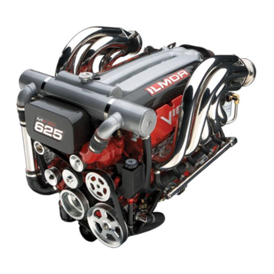
Page 3: Welcome
ILMOR Marine Engines would like to thank you for selecting the Ilmor MV10 for your boating needs. The MV10 engine by ILMOR Marine represents a new opportunity for the boating world to enjoy a great performing, totally new powerplant. Based on a lightweight, high-output V10, the concept of this engine package is to reliably deliver high-performance boating pleasure without the typical complications. -
Page 4: Safety Information
All maintenance and lubrication schedules, when properly adhered to will ensure long life and great performance of the MV10 engine. When service and maintenance are required please return the boat to an ILMOR Marine dealer or authorized ILMOR service center. Replacement Parts A list of ILMOR approved MV10 parts are in the appendix of this manual. -
Page 5: Hoist Points For Engines Equipped With Lifting Lugs
Owner’s Manual & Installation Instructions Revision 6e Hoist Points for engines equipped with lifting lugs. WARNING Retaining bolt must be torqued to 50 ft/lb. A lifting strap or chain must be used to lift the MV10 engine. The chain must have a load bearing capacity of at least 1,000lb. All hooks, cranes and rigging used to lift the engine must also have at least 1,000lb load capacity. -
Page 6: Hoist Points For Engines
Owner’s Manual & Installation Instructions Revision 6e Hoist Points for engines. 1. Insert Lifting Hook (part number: pt00839a) by feeding insertion cable between the second and third sets of intake port runners (from the front of the engine) and out through the top of the intake manifold as shown. -
Page 7: Mounting The Engine
Owner’s Manual & Installation Instructions Revision 6e Mounting the Engine The MV10 is supplied with motor mounts which allows installation into typical V-hulls and catamarans with single, dual or triple engine configurations. Engine Mounting: Plate Options, views from stern to bow: Often referred to as an “offshore”... - Page 8 Owner’s Manual & Installation Instructions Revision 6e Mounting the Engine cont’d Staggered Front (PE00562, PE00563) Stringer mounting hole spacing: From crankshaft, 6.9” (low side) & 14.9” (high side). Typically used on twin engine v-hull applications with space limitations requiring one engine mounted slightly ahead of the other (staggered).
- Page 9 Owner’s Manual & Installation Instructions Revision 6e Mounting the Engine cont’d Engine Mounting: Motor Mount Options, views from stern to bow: Foot Mounts, 2 required (PE00524) Stringer mounting hole spacing: 22.5” centered. Common mounting system through the use of individual mounts on each side of the engine with no plate connecting them.
-
Page 10: Leveling Engine
Owner’s Manual & Installation Instructions Revision 6e Leveling Engine When leveling the engine, good reference surfaces are the fuel rail and the top edges of the valve covers, as these surfaces run parallel to the crankshaft centerline. Page 10... -
Page 11: Exhaust System
Owner’s Manual & Installation Instructions Revision 6e Exhaust System There are currently two styles of headers available for the MV10, straight back and down- turned, with several configurations of the down-turned offered. Fig. 3 Down-Turned (MVP 0117) Fig. 4 Straight Back (MVP 0118) Down-turned headers are the standard headers offered with the MV10 (Fig. - Page 12 Begin by loosely installing all the hardware and then draw the header in evenly by going over all bolts several times. Final torque should be 25 ft lb. Tailpipes for a standard Bravo set-up are available directly from ILMOR Marine Engines under part number MVP 0152. Custom tailpipes are to be obtained directly from CMI.
-
Page 13: Fuel Injection System - All Models
ILMOR, including the use of non-ILMOR specified service parts unless such modification or use of parts is requested and approved by ILMOR in writing. Please call ILMOR Marines Engines before altering the fuel delivery system in any way. - Page 14 Owner’s Manual & Installation Instructions Revision 6e Fuel Injection System – All Models cont’d FUEL RAILS The fuel rails are fed from the regulator output using a quick-release fitting and a combination of hard line and USCG approved fuel line. The fuel rails are connected at the rear of the engine through the use of the OEM, crossover pipe.
-
Page 15: Fuel Injection System - 550 And Older 625 Models
Owner’s Manual & Installation Instructions Revision 6e Fuel Injection System – 550 and older 625 models (without return to tank fuel) FUEL SYSTEM DIAGRAM A. MVP0115 TANDEM COOLER OIL/FUEL B. MVP0136 WATER FUEL SEPARATOR C. MVP0025 FUEL PUMP D. MVP0111 FUEL FILTER/REGULATOR E. - Page 16 Owner’s Manual & Installation Instructions Revision 6e Fuel Injection System - 550 and older 625 models cont’d (without return to tank fuel) FUEL FILTER / WATER SEPARATOR – Fig. 9 Fuel supply from the tank must be run directly to the fuel filter / water separator. The separator is located near the rear of the engine on the port side.
- Page 17 Owner’s Manual & Installation Instructions Revision 6e Fuel Injection System - 550 and older 625 models cont’d (without return to tank fuel) FUEL FILTER/ WATER SEPARATOR ADAPTER A – Fuel inlet from tank. Use right-hand or left- hand as necessary, following arrows cast into filter base.
- Page 18 Owner’s Manual & Installation Instructions Revision 6e Fuel Injection System - 550, older 625, and older 7-10 models FUEL/OIL COOLER Starboard (Right) Side: Fig. 12 Port (Left) Side: Right Side Left Side A – Seawater Outlet H – Seawater Inlet Fig.
-
Page 19: Fuel Injection System - 570, Newer 625, And 7-10 Models
Owner’s Manual & Installation Instructions Revision 6e Fuel Injection System – 570, newer 625, and 7-10 models (with return to tank fuel) Page 19... -
Page 20: Throttle Cable Connection
Owner’s Manual & Installation Instructions Revision 6e Throttle Cable Connection Throttle Stop and Cable Mount - The MV10 is provided with mountings suitable for use with industry standard Morse cables. The throttle is spring loaded and is closed (or at idle) when resting on the throttle lever stop screw. -
Page 21: Engine Cooling System
The heat exchanger uses seawater to extract heat from the coolant. A stainless steel overflow tank with ~2 quart capacity is supplied with all new MV-10 packages. Sea Water Plumbing The sea water system should be fitted with a high capacity sea strainer to remove debris from entering the external cooling system. - Page 22 Owner’s Manual & Installation Instructions Revision 6e Engine Cooling System cont’d Expansion Tank To ensure the engine remains completely filled with coolant the engine installer must fit an expansion tank to the system. The tank must have at least a two quart capacity, be vented to atmosphere and have a provision for checking the fluid level.
- Page 23 Owner’s Manual & Installation Instructions Revision 6e Engine Cooling System cont’d Cooling System Bleed Screw To minimize the likelihood of retaining air pockets within the engine, an air bleed screw is provided near the front of the engine on top of the thermostat housing (See Fig. 16). This bleed must be cracked open while the engine is being filled with coolant.
- Page 24 Owner’s Manual & Installation Instructions Revision 6e Engine Cooling System cont’d Filling the coolant system To fill the coolant system, begin by removing the pressure cap located on the heat exchanger at the front of the engine and fill through the filler neck. Once the heat exchanger is completely filled, wait three minutes while the system continues to settle.
-
Page 25: Power Steering System
Recommended power steering fluid is Mopar Power Steering Fluid MS 5931 or equivalent. This fluid can be obtained from any Chrysler/Dodge/Jeep dealership or directly through Ilmor Marine Engines. DO NOT use automatic transmission fluid (ATF). POWER STEERING COOLER A –... -
Page 26: Electrical System
Owner’s Manual & Installation Instructions Revision 6e Electrical System IMPORTANT The electrical system on the MV10 is a 12 volt negative ground system. Any attempt to connect the battery in a reverse polarity manner could lead to extensive damage of the electronics. -
Page 27: Electrical System - Fuse Box
Owner’s Manual & Installation Instructions Revision 6e Electrical System – Fuse Box Fuse box Cover Removal The Fuse box and ECU cover is constructed of carbon fiber and is mounted to the engine by three rubber grommets, like the fuel rail covers. -
Page 28: Electrical System - Boat/Engine Interface Wiring
The instrument and switch loom for the dash panel is wired through a matching female pigtail. The female connector and pigtail is available from ILMOR Marine Engines (see MV10 Service Parts Listing for part numbers). - Page 29 Owner’s Manual & Installation Instructions Revision 6e Electrical System – Boat/Engine Interface Wiring cont’d Pin 5 (Purple) IGN/RUN - This wire provides battery positive from the ignition switch in the start or run position to the engine. This power is sent to the JTEC ECU to turn the engine electronics on or off.
- Page 30 Owner’s Manual & Installation Instructions Revision 6e Electrical System – Boat/Engine Interface Wiring cont’d Page 30...
-
Page 31: Electrical System - Engine Wiring
Owner’s Manual & Installation Instructions Revision 6e Electrical System - Engine Wiring Page 31... -
Page 32: Electrical System - Ecm Pin-Out
Owner’s Manual & Installation Instructions Revision 6e Electrical System - ECM Pin-Out The powertrain control module utilizes three, color-coded, 32-pin connectors. Connector A: Connector B: Pin # Function Pin # Function Ign. Coil Driver #4 Ignition Switch Output Fuel Injector #7 Ign. - Page 33 Owner’s Manual & Installation Instructions Revision 6e Electrical System - ECM Pin-Out cont’d Connector C: Pin # Function Automatic Shutdown Relay Control (ASD) Knock Sensor 8-11 Automatic Shutdown Relay Output 13-16 - Starter Motor Relay Control Knock Sensor #2 Fuel Pump Relay 20-24 - Alternator Source 26-32 -...
-
Page 34: Electrical System - Instrumentation
Owner’s Manual & Installation Instructions Revision 6e Electrical System – Instrumentation The MV10 is shipped with the following instrument sending units from the factory. The signals from these senders will be wired per standard industry practice within the 9 pin engine/boat interface connector as described in the previous section. -
Page 35: Electrical System - Sensor Layout
Owner’s Manual & Installation Instructions Revision 6e Electrical System - Sensor Layout Fig. 21 Fig. 22 A – Oil Temp. Alarm C – Water Temp. Sender (Gauge) B – Water Temp. Alarm Sensor Torques See: "Engine Fastener Torque Specifications, Sensor Torques”... -
Page 36: Engine Monitoring Alarm System
Revision 6e Engine Monitoring Alarm System The ILMOR Marine engine alarm system will indicate an alarm condition if any of the monitored engine parameters falls out of the nominal operating range. In all cases the proper response to the alarm is to throttle back immediately and check the gauges to see which system is out of range. -
Page 37: Prior To Start Procedures
Owner’s Manual & Installation Instructions Revision 6e Prior to Start Procedures Oil Level (HOT) ® Use only Mobil 1 Synthetic Motor Oil, (see “Engine Specifications” for correct viscosity) The oil level indications on the dipstick are most accurate when the engine is sitting with the crankshaft horizontal. -
Page 38: Starting The Mv10
13 volts. Allow the engine to reach normal operating temperature (170ºF). Should the engine temperature rises beyond 210ºF shut off the engine immediately and determine the cause or contact an Ilmor authorized dealer/service center. Page 38... -
Page 39: Engine Break-In
It is preferable to perform the break in over many stages with a full cool down cycle after each outing. Check the coolant level often to ensure proper level. WARNING At the end of the 25 hour break-in period bring the boat to an authorized ILMOR marina or service center for the 25 hour service. Page 39... -
Page 40: Stopping The Engine
Owner’s Manual & Installation Instructions Revision 6e Stopping the Engine When stopping the engine: 1. Bring the throttle levers to the idle position 2. Allow the engine to return to a stable low idle speed 3. Return the gear selector to the neutral position 4. -
Page 41: Fuel Requirements
Revision 6e Fuel Requirements The ILMOR MV10 550, 570, 625, and 7-10 are high-performance engine and requires premium fuel, with a minimum octane rating of 91 (R+M)/2. Use of lower octane fuels will cause spark knock (pinging). Continued heavy spark knock can cause severe engine damage. -
Page 42: Maintenance - Oil Change
Schedule” in the maintenance section. The oil should also be changed if for any reason its temperature has exceeded 300º F. Always change the oil filter each time the oil is changed, using only Ilmor approved filters as listed in “Service Parts”. -
Page 43: Maintenance - Engine Coolant
Revision 6e Maintenance - Engine Coolant Each MV10 is shipped from Ilmor Marine pre-filled with the proper amount of coolant. Once the engine and overflow tank are mounted in the boat, check to be sure the heat exchanger is filled completely. Add a 50/50 coolant mixture to the overflow tank until the tank is filled halfway. -
Page 44: Maintenance - 25 Hour Service
Check the battery condition. Check all battery connections are tight. Check motor mounts and mounting bolts. Check starter, bell-housing bolts, transmission bolts are tight. Maintenance – Engine Life After 245 hours of service or 5 years, it is recommended that all mv-10 engines be refurbished. Page 44... -
Page 45: Maintenance - Winterization
Owner’s Manual & Installation Instructions Revision 6e Maintenance - Winterization It is recommended to fog these engines if prolonged (8 weeks) or more of storage is expected or if the boat is stored for the winter (Do not fog engine until stalling occurs). A fuel stabilizer should added at the end of the season before storage. -
Page 46: Maintenance - Ignition System
Owner’s Manual & Installation Instructions Revision 6e Maintenance – Ignition System Spark Plug High Tension Cables Resistance Minimum Maximum 250 Ohms Per Inch 750 Ohms Per Inch 3000 Ohms Per Foot 9,000 Ohms Per Foot Ignition Coil Resistance Primary Resistance at 21°C-27°C (70°F-80°F) 0.53 to 0.65 Ohms Secondary Resistance at 21°C-27°C (70°F-80°F) 10,900 to 14,700 Ohms... -
Page 47: Engine Fastener Torque Specifications
Owner’s Manual & Installation Instructions Revision 6e Engine Fastener Torque Specifications Main Studs 85 ft lb Main Cross Bolts 40 ft lb Cam Thrust Plate 210 in lb w/ blue loctite Cam Gear 200 in lb w/ blue loctite Rear Crank Seal Cover 95 in lb Lifter Yokes 95 in lb... - Page 48 Owner’s Manual & Installation Instructions Revision 6e Engine Fastener Torque Specifications (continued) Damper 130 ft lb (small bolt style) 250 ft lb (large bolt style) Crank Pulley 17 ft lb w/ blue loctite 3/8 NPT plug 18 ft lb w/ PST 1/8 NPT plug 95 in lb w/ PST...
-
Page 49: Maintenance - Mv10 Maintenance Schedule
Owner’s Manual & Installation Instructions Revision 6e Maintenance - MV10 Maintenance Schedule Item Daily Hours Hours Hours Yearly Check oil level Check coolant level Check power steering fluid level Check transmission oil level Check sea strainer Check fuel system for leaks Check exhaust system for water leaks Cooling system Check condition of hoses and clamps Serpentine belt Check for cracks and tension... -
Page 50: Engine Specifications
Owner’s Manual & Installation Instructions Revision 6e Engine Specifications 550, 570, 625, and 7-10 models Required Fuel Octane 91 (R + M)/2 Minimum Mopar 5 Yr/100,000 mile formula antifreeze Engine Coolant (MS-9769) (50/50 mix) 550, 570, and 625 models 15W50 Mobil 1® Synthetic Engine Oil 7-10 model 0W40 Mobil 1®... -
Page 51: Mv10 Service Parts Listing
Owner’s Manual & Installation Instructions Revision 6e MV10 Service Parts Listing ALTERNATOR, SAE J1171 PE00448 BELT, w/ power steering MVP0165 BELT, w/o power steering MVP0166 BUSHING, Bravo Bellhousing MVP0037 CAP, heat exchanger, 16lb MVP0003 CLAMP, exhaust, downturned headers MVP0092 CLAMP, exhaust, straightback headers MVP0091 CLAMP, T-bolt MVP0137... - Page 52 Owner’s Manual & Installation Instructions Revision 6e 550 and older 625 models (without return fuel) MVP0111 570 and newer 625 models (with return fuel) REGULATOR, Fuel MVP0438 7-10 model MVP0430 SENDER, Oil Pressure MVP0168 SENDER, Oil Temperature MVP0129 SENDER, Water Temperature MVP0060 SENSOR, Knock MVP3700...
Need help?
Do you have a question about the MV-10 and is the answer not in the manual?
Questions and answers