Table of Contents
Advertisement
Quick Links
Advertisement
Table of Contents

Related Manuals for D-Link SmartPro DGS-1500-20


Summary of Contents for D-Link SmartPro DGS-1500-20
-
Page 2: Table Of Contents
Table of Contents D-Link Web Smart Switch User Manual Table of Contents Table of Contents ............................. i About This Guide ............................. 1 Terms/Usage ..............................1 Copyright and Trademarks ..........................1 Product Introduction ........................... 2 DGS-1500-20 ..............................3 Front Panel ..............................3 Rear Panel .............................. - Page 3 Table of Contents D-Link Web Smart Switch User Manual Save Configuration ........................... 21 Save Log ..............................21 Tool Bar > Tool Menu ..........................21 Reset ................................ 21 Reset System ............................21 Reboot Device ............................22 Configuration Backup and Restore ......................22 Firmware Backup and Upgrade ........................
- Page 4 Table of Contents D-Link Web Smart Switch User Manual L2 Functions > LLDP > LLDP Statistics ....................52 L3 Functions > IP Interface ........................53 L3 Functions > Static Route ........................53 L3 Functions > Routing Table Finder ....................... 54 L3 Functions >...
- Page 5 Table of Contents D-Link Web Smart Switch User Manual logout ................................ 81 ping ................................81 reboot ............................... 81 reset config ............................... 82 show ipif ..............................82 show switch .............................. 83 config account admin password ....................... 83 save ................................84 debug info ..............................84 Appendix A - Technical Specifications .......................
-
Page 6: About This Guide
Reproduction in any manner whatsoever without the written permission of D-Link Corporation is strictly forbidden. Trademarks used in this text: D-Link and the D-LINK logo are trademarks of D-Link Corporation; Microsoft and Windows are registered trademarks of Microsoft Corporation. Other trademarks and trade names may be used in this document to refer to either the entities claiming the marks and names or their products. -
Page 7: Product Introduction
The SmartConsole easily allows customers to discover multiple D-Link web smart switches with the same L2 network segment connected to the user’s local PC. With this utility, users do not need to change the IP address of the PC and provide easy initial settings of the smart switches. -
Page 8: Dgs-1500-20
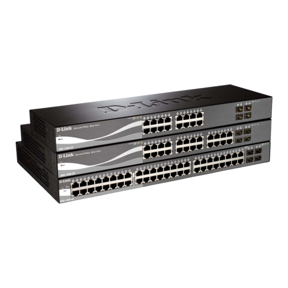
Front Panel SFP ports for optical transceivers Figure 1.1 – DGS-1500-20 Front Panel Power LED : The Power LED lights up when the Switch is connected to a power source. Reset: By pressing the Reset button, the Switch will change back to the default configuration and all changes will be lost. -
Page 9: Rear Panel
1 Product Introduction D-Link Web Smart Switch User Manual CAUTION: The MiniGBIC ports should use UL listed Optical Transceiver product, Rated Laser Class I. 3.3Vdc. Reset: By pressing the Reset button, the Switch will change back to the default configuration and all changes will be lost. -
Page 10: Hardware Installation
D-Link Web Smart Switch User Manual Hardware Installation This chapter provides unpacking and installation information for the D-Link SmartPro Switch. Step 1: Unpacking Open the shipping carton and carefully unpack its contents. Please consult the packing list located in the User Manual to make sure all items are present and undamaged. -
Page 11: Step 3 - Plugging In The Ac Power Cord
2 Hardware Installation D-Link Web Smart Switch User Manual Figure 2.3 – Mount the Switch in the rack or chassis Please be aware of following safety Instructions when installing: A) Elevated Operating Ambient - If installed in a closed or multi-unit rack assembly, the operating ambient temperature of the rack environment may be greater than room ambient. -
Page 12: Power Failure
2 Hardware Installation D-Link Web Smart Switch User Manual Power Failure As a precaution, the switch should be unplugged in case of power failure. When power is resumed, plug the switch back in. -
Page 13: Getting Started
This chapter introduces the management interface of D-Link SmartPro Switch. Management Options The D-Link SmartPro Switch can be managed through any port on the device by using the Web-based Management, or through any PC using the SmartConsole Utility or CLI commands. -
Page 14: Login Web-Based Management
English. Figure 3.3 – Logon Dialog Box Smart Wizard After a successful login, the Smart Wizard will guide you through essential settings of the D-Link Web Smart Switch. Please refer to the Smart Wizard Configuration section for details. Web-based Management By clicking the Exit button in the Smart Wizard, you will enter the Web-based Management interface. - Page 15 CD-Rom or DVD-Rom) and click OK. Follow the on-screen instructions to install the utility. Upon completion, go to Start > Programs > D-Link SmartConsole Utility and open the SmartConsole Utility. Connect the Smart Switch to the same L2 network segment of your PC and use the SmartConsole Utility to discover the Smart Switches.
-
Page 16: Smartconsole Utility
D-Link Web Smart Switch User Manual SmartConsole Utility The D-Link SmartConsole Utility allows the administrator to quickly discover all D-Link smart switches, which are in the same domain of the PC, collect traps and log messages, and quick access to basic configurations of the switch. -
Page 17: Log
4 SmartConsole Utility D-Link Web Smart Switch User Manual Click this icon to launch the Log window. Click View Log to show the events of the SmartConsole Utility and the device. Date/Time indicates when the message was received, IP denotes where it comes from and Status shows the content of this log message. -
Page 18: Help
4 SmartConsole Utility D-Link Web Smart Switch User Manual Figure 4.5 – SmartConsole File Monitor Save: Records the setting of the Device List as default for the next time the SmartConsole Utility is used. Monitor Save As: Records the setting of the Device List in an appointed filename and file path. -
Page 19: Device Configuration
4 SmartConsole Utility D-Link Web Smart Switch User Manual Device Configuration The Device Configuration in the SmartConsole Utility has five icons: Device Settings Device Password Manager Multi Firmware Upgrade DHCP Refresh Web Access and the device buttons for the Device List. - Page 20 4 SmartConsole Utility D-Link Web Smart Switch User Manual Device Password Manager Select a switch from the Device List. Click on this icon to launch the Device Password Manager window. Here you can enter a new password and confirm it.
-
Page 21: Add(+), Delete(-) And Discover The Device
4 SmartConsole Utility D-Link Web Smart Switch User Manual Figure 4.10 – DHCP Refresh Web Access Select a switch from the Device List. Click this icon to launch your Internet browser (eg. The Internet Explorer). Here you can configure the Switch through the Web-based Management utility. You may also get into the Web-based Management by double-clicking the device in the device list. - Page 22 4 SmartConsole Utility D-Link Web Smart Switch User Manual Definitions of the Device List features: Monitor: Checking the Monitor box and the SmartConsole will collect the trap and log data from the device. in the monitor means the device was discovered by SmartConsole. Click the icon to have the device to continue updating the information, such as system log or trap to the SmartConsole Utility.
-
Page 23: Configuration
Smart Wizard Configuration After a successful login, the Smart Wizard will guide you through essential settings of the D-Link Web Smart Switch. If you do not plan to change anything, click Exit to leave the Wizard and enter the Web Interface. -
Page 24: Snmp Settings
5 Configuration D-Link Web Smart Switch User Manual Figure 5.2 – Password setting in Smart Wizard SNMP Settings The SNMP Setting allows you to quickly enable/disable the SNMP function. The default SNMP Setting is Disabled. Click Enabled and then click Apply to make it effective.. -
Page 25: Web-Based Management
5 Configuration D-Link Web Smart Switch User Manual If you want to change the IP settings, click OK and start a new web browser. Figure 7 – Confirm the changes of IP address in Smart Wizard Web-based Management After clicking the Exit button in Smart Wizard you will see the screen below: Figure 5.4 –... -
Page 26: Tool Bar > Save Menu
5 Configuration D-Link Web Smart Switch User Manual Finally, by clicking on the D-Link logo at the upper-left corner of the screen you will be redirected to the local D-Link website. Tool Bar > Save Menu The Save Menu provides Save Configuration and Save Log functions. -
Page 27: Reboot Device
5 Configuration D-Link Web Smart Switch User Manual Reboot Device Provide a safe way to reboot the system. Click Reboot to restart the switch. Figure 5.11 – Tool Menu > Reboot Device Configuration Backup and Restore Allow the current configuration settings to be saved to a file (not including the password), and if necessary, you can restore configuration settings from this file. -
Page 28: Tool Bar > Smart Wizard
Tool Bar > Online Help The Online Help provides two ways of online support: Online Support Site will lead you to the D-Link website where you can find online resources such as updated firmware images; User Guide can offer an immediate reference for the feature definition or configuration guide. - Page 29 5 Configuration D-Link Web Smart Switch User Manual Figure 5.15 – User Guide Micro Site...
-
Page 30: Function Tree
5 Configuration D-Link Web Smart Switch User Manual Function Tree All configuration options on the switch are accessed through the Setup menu on the left side of the screen. Click on the setup item that you want to configure. The following sections provide more detailed description of each feature and function. -
Page 31: System > System Settings
30 minutes, and the default setting is 5 minutes. Group Interval: The D-Link Web Smart Switch will routinely send report packets to the SmartConsole Utility in order to maintain the information integrity. The user can adjust the Group Interval to optimal frequency. -
Page 32: System > Port Settings
5 Configuration D-Link Web Smart Switch User Manual New Password: Enter the new password that you wish to set on the Switch to authenticate users attempting to access Administrator Level privileges on the Switch. The user may set a password of up to 20 characters. -
Page 33: System > Dhcp Auto Configuration
5 Configuration D-Link Web Smart Switch User Manual System > DHCP Auto Configuration This page allows you to enable the DHCP Auto Configuration feature on the Switch. When enabled, the Switch becomes a DHCP client and gets the configuration file from a TFTP server automatically on next boot up. -
Page 34: System > Power Saving
5 Configuration D-Link Web Smart Switch User Manual Profile Name: Specifies the profile name. Time(HH MM): Specifies the Start Time and End Time. Weekdays: Specifies the work day. Date: Select Date and specifies the From Day and To Day of the time profile. -
Page 35: Vlan > 802.1Q Vlan
5 Configuration D-Link Web Smart Switch User Manual VLAN > 802.1Q VLAN A VLAN is a group of ports that can be anywhere in the network, but communicate as though they were in the same area. VLANs can be easily organized to reflect department groups (such as R&D, Marketing), usage groups (such... -
Page 36: Vlan > Vlan Status
5 Configuration D-Link Web Smart Switch User Manual Figure 5.27 – Configuration > 802.1Q VLAN > Example VIDs Figure 5.28 – Configuration > 802.1Q VLAN > VID Assignments VLAN > VLAN Status The VLAN Status page is for user to search the VLAN which has already existed by VLAN ID or VLAN Name. -
Page 37: Vlan > Gvrp > Gvrp Port Settings
5 Configuration D-Link Web Smart Switch User Manual Join Time (100-100000): Indicates the time in milliseconds that PDUs are transmitted. The default value is 200ms. Leave Time (100-100000): Indicates the amount of time in milliseconds that the device waits before leaving its GARP state. -
Page 38: Vlan > Voice Vlan > Voice Vlan Global Settings
5 Configuration D-Link Web Smart Switch User Manual GVRP: The Group VLAN Registration Protocol (GVRP) enables the port to dynamically become a member of a VLAN. GVRP is Disabled by default. Ingress Checking: This field can be toggled using the space bar between Enabled and Disabled. Enabled enables the port to compare the VID tag of an incoming packet with the PVID number assigned to the port. -
Page 39: Vlan > Voice Vlan > Voice Vlan Port Settings
5 Configuration D-Link Web Smart Switch User Manual There are some pre-defined OUIs and when the user configures personal OUI, these pre-defined OUIs must be avoided. Below are the pre-defined voice traffic’s OUI: Vendor Mnemonic Name 00:E0:BB 3COM 3com 00:03:6B... -
Page 40: Vlan > Voice Vlan > Voice Device List
Similar as Voice VLAN, Auto Surveillance VLAN is a feature that allows you to automatically place the video traffic from D-Link IP cameras to an assigned VLAN to enhance the IP surveillance service. With a higher priority and individual VLAN, the quality and the security of surveillance traffic are guaranteed. The Auto Surveillance VLAN function will check the source OUI/MAC address / VLAN ID on the incoming packets. -
Page 41: L2 Functions > Jumbo Frame
Click Apply to implement changes of Auto Surveillance VLAN global settings. User-defined MAC Settings: Component Type: Auto Surveillance VLAN will automatically detect D-Link Surveillance Devices by default. There are another five surveillance components that could be configured to be auto-detected by the Auto Surveillance VLAN. -
Page 42: L2 Functions > Loopback Detection
5 Configuration D-Link Web Smart Switch User Manual Source Port Selection: TX: Duplicates the data transmitted from the source port and forwards it to the Target Port. Click “all” to include all ports into port mirroring. RX: Duplicates the data that received from the source port and forwards it to the Target Port. Click “all” to include all ports into port mirroring. -
Page 43: L2 Functions > Mac Address Table > Static Mac
5 Configuration D-Link Web Smart Switch User Manual L2 Functions > MAC Address Table > Static MAC This feature provides two distinct functions. The Disable Auto Learning table allows turning off the function of learning MAC address automatically, if a port isn't specified as an uplink port (for example, connects to a DHCP Server or Gateway). -
Page 44: L2 Functions > Spanning Tree > Stp Global Settings
5 Configuration D-Link Web Smart Switch User Manual L2 Functions > Spanning Tree > STP Global Settings The Switch implements two versions of the Spanning Tree Protocol, the Rapid Spanning Tree Protocol (RSTP) as defined by the IEEE 802.1w specification and a version compatible with the IEEE 802.1D STP. -
Page 45: L2 Functions > Spanning Tree > Stp Port Settings
5 Configuration D-Link Web Smart Switch User Manual L2 Functions > Spanning Tree > STP Port Settings STP can be set up on a port per port basis. In addition to setting Spanning Tree parameters for use on the switch level, the Switch allows for the configuration of groups of ports, each port-group of which will have its own spanning tree, and will require some of its own configuration settings. -
Page 46: L2 Functions > Link Aggregation > Port Trunking
5 Configuration D-Link Web Smart Switch User Manual Priority: Specify the priority of each port. Selectable range is from 0 to 240, and the default setting is 128. The lower the number, the greater the probability the port will be chosen as a root port. -
Page 47: L2 Functions > Multicast > Igmp Snooping
5 Configuration D-Link Web Smart Switch User Manual Figure 5.44 – L2 Functions > Link Aggregation > LACP Port Settings From Port: The beginning of a consecutive group of ports may be configured starting with the selected port. To Port: The ending of a consecutive group of ports may be configured starting with the selected port. - Page 48 5 Configuration D-Link Web Smart Switch User Manual Figure 5.45 – L2 Functions > Multicast > IGMP Snooping By default, IGMP is disabled. If enabled, the IGMP Global Settings will need to be entered: Host Timeout (130-153025 sec): This is the interval after which a learned host port entry will be purged. For each host port learned, a 'Port Purge Timer' runs for 'Host Port Purge Interval'.
-
Page 49: L2 Functions > Multicast > Multicast Forwarding
5 Configuration D-Link Web Smart Switch User Manual Press Apply for changes to take effect. A router port configured manually is a Static Router Port, and a Dynamic Router Port is dynamically configured by the Switch when a query control message is received. -
Page 50: L2 Functions > Multicast > Multicast Filtering Mode
5 Configuration D-Link Web Smart Switch User Manual L2 Functions > Multicast > Multicast Filtering Mode The Multicast Filtering Mode function allows users to select the filtering mode for IGMP group per VLAN basis. Figure 5.49 – L2 Functions > Multicast > Multicast Filtering Mode VLAN ID: Specifies the VLAN ID. -
Page 51: L2 Functions > Sntp > Timezone Settings
5 Configuration D-Link Web Smart Switch User Manual Click Apply to implement changes made. When selecting Local for the clock source, users can select from one of two options: Manually Time Settings: Users input the system time manually. Sync To PC: The system time will be synchronized from the local computer. -
Page 52: L2 Functions > Lldp > Lldp Port Settings
5 Configuration D-Link Web Smart Switch User Manual For the receiving of LLDP packets, the switch will learn the information from the LLDP packets advertised from the neighbor in the neighbor table. Click Apply to make the change effective. Message TX Hold Multiplier (2-10): This parameter is a multiplier that determines the actual TTL value used in an LLDPDU. -
Page 53: L2 Functions > Lldp > 802.1 Extension Tlv
5 Configuration D-Link Web Smart Switch User Manual System Description: Specifies whether the System Description TLV is enabled on the port. The possible field values are: Enabled – Enables the System Description TLV on the port. Disabled – Disables the System Description TLV on the port. -
Page 54: L2 Functions > Lldp > Lldp Management Address Settings
5 Configuration D-Link Web Smart Switch User Manual Figure 5.55 – L2 Functions > LLDP > 802.3 extension TLV From Port/To Port: A consecutive group of ports may be configured starting with the selected port. MAC/PHY Configuration/Status: Specifies whether the MAC/PHY Configuration Status is enabled on the port. -
Page 55: L2 Functions > Lldp > Lldp Management Address Table
5 Configuration D-Link Web Smart Switch User Manual Figure 5.56 – L2 Functions > LLDP >LLDP Management Address Settings From Port/To Port: A consecutive group of ports may be configured starting with the selected port. Address Type: Specify the LLDP address type on the port. The value is always IPv4. -
Page 56: L2 Functions > Lldp > Lldp Remote Port Table
5 Configuration D-Link Web Smart Switch User Manual Figure 5.58 – L2 Functions > LLDP > LLDP Port Settings Port : Displays the port number. Port ID Subtype: Displays the port ID subtype. Port ID: Displays the port ID (Unit number/Port number). -
Page 57: L2 Functions > Lldp > Lldp Statistics
5 Configuration D-Link Web Smart Switch User Manual To view the settings for a remote port, click View Normal and the following page displays. Figure 5.60 – L2 Functions > LLDP > LLDP Remote Port Table(Normal) To view the detail settings for a remote port, click View Detailed and the following page displays. -
Page 58: L3 Functions > Ip Interface
5 Configuration D-Link Web Smart Switch User Manual RxPortTLVsDiscarded – Each LLDP frame can contain multiple pieces of information, known as TLVs. If a TLV is malformed, it is counted and discarded. RxPortTLVsUnrecognized – Displays the number of well-formed TLVs, but with an known type value. -
Page 59: L3 Functions > Routing Table Finder
5 Configuration D-Link Web Smart Switch User Manual L3 Functions > Routing Table Finder The Routing Table Finder page shows the current IP routing table of the Switch. To find a specific IP route, enter an IP address into the Network Address field and click Search. -
Page 60: L3 Functions > Arp > Gratuitous Arp
5 Configuration D-Link Web Smart Switch User Manual Click Delete to delete the information of ARP table. L3 Functions > ARP > Gratuitous ARP The Gratuitous ARP page provides users to configure the Gratuitous ARP global settings. Figure 5.68 – L3 Functions > ARP > Gratuitous ARP Specifies the Send when IP Interface is up, Send when duplicated IP is detected and Learn received Gratuitous ARP are enabled or disabled then click Apply to take effect. -
Page 61: Qos > Bandwidth Control
5 Configuration D-Link Web Smart Switch User Manual Hold Time (100-255): This parameter may be set for the time, in seconds the Switch will hold information sent to it from other switches, utilizing the Discovery Interval. The user may set the hold time from 100 to 255 seconds. -
Page 62: Security > Trusted Host
5 Configuration D-Link Web Smart Switch User Manual Figure 5.71 – QoS > 802.1p/DSCP Select QoS Mode: Specifies the QoS mode to be 802.1p or DSCP. Queuing Mechanism: Strict Priority: Denoting a Strict scheduling will set the highest queue to be emptied first while the... -
Page 63: Security > Port Security
5 Configuration D-Link Web Smart Switch User Manual Security > Port Security Port Security is a security feature that prevents unauthorized computers (with source MAC addresses) unknown to the Switch prior to stopping auto-learning processing from gaining access to the network. -
Page 64: Security > Safeguard Engine
Click Select All button to check all ports or click Clear button to uncheck all ports. Security > Safeguard Engine D-Link’s Safeguard Engine is a robust and innovative technology that automatically throttles the impact of packet flooding into the switch's CPU. This function helps to protect the Web-Smart Switch from being interrupted by malicious viruses or worm attacks. -
Page 65: Security > Dhcp Server Screening
5 Configuration D-Link Web Smart Switch User Manual Figure 5.77 – Security > ARP Spoofing Prevention Setting Enter the IP Address, MAC Address, Ports and then click Add to create a checking/filtering rule. Click Delete to remove an existing rule and Delete All to clear all the entries. -
Page 66: Aaa > Radius Server
5 Configuration D-Link Web Smart Switch User Manual Figure 5.79 – Security > SSL Settings NOTE: When SSL is enabled, it will take longer time to open a web page due to encryption. After saving configuration, please wait around 10 seconds for the system summery page. -
Page 67: Aaa > 802.1X > 802.1X Global Settings
5 Configuration D-Link Web Smart Switch User Manual AAA > 802.1X > 802.1X Global Settings Network switches provide easy and open access to resources, by simply attaching a client PC. Unfortunately this automatic configuration also allows unauthorized personnel to easily intrude and possibly gain access to sensitive data. -
Page 68: Aaa > 802.1X > 802.1X User
The ACL Configuration Wizard will aid with the creation of access profiles and ACL Rules. The ACL Wizard will create the access rule and profile automatically. For DGS-1500-20/28, the maximum usable profiles are 50 and with 200 Rules in total for the switch. For DGS-1500-52, the maximum usable profiles are 50 and with... -
Page 69: Acl > Access Profile List
5 Configuration D-Link Web Smart Switch User Manual Figure 5.84 – ACL > ACL Wizard From: Specify the origin of accessible packets. The possible values are: Any - Indicates ACL action will be on packets from any source. MAC Address - Indicates ACL action will be on packets from this MAC address. - Page 70 5 Configuration D-Link Web Smart Switch User Manual Figure 5.85 – ACL > Access Profile List The contents of Access Profile List table include: Profile ID: Indicates the profile Identification number. The possible configured profile IDs are 1~50, and profile ID 51 is reserved for Voice VLAN.
- Page 71 5 Configuration D-Link Web Smart Switch User Manual Figure 5.87 – Add Access Profile 2) Selecting the field of interest will display the related columns in the lower part of the page. Enter the filtering mask and click Apply when done. A filtering mask is to specify the digit that you want to check. For example, if you want to check a network of 192.168.1.0/24, then you should enter the IP mask as...
-
Page 72: Acl > Acl Finder
5 Configuration D-Link Web Smart Switch User Manual Figure 5.90 – Add Access Rule Profile Information displays the information to which the rule is being added to, including Profile ID and Source MAC. In Rule Detail, you can specify the details of an access rule. Below are all the possible parameters that can be set. -
Page 73: Snmp > Trap To Smartconsole
5 Configuration D-Link Web Smart Switch User Manual SNMP > Trap to SmartConsole The Trap to SmartConsole page allows user the set the difference status of SNMP notifications trapped to the Smartconsole. Figure 5.93 – SNMP > Trap to SmartConsole Destination IP: Specifies the destination IP. -
Page 74: Snmp > Snmp > Snmp User
5 Configuration D-Link Web Smart Switch User Manual SNMP Authentication Traps: Specifies the device to send authentication failure notifications. Device Bootup: Specifies the device to send bootup notifications. Port Link Up/Link Down: Specifies the device to send notifications when port linkup or link down. -
Page 75: Snmp > Snmp > Snmp View
5 Configuration D-Link Web Smart Switch User Manual Write View Name: Specify a SNMP group name for users that are allowed SNMP write privileges to the Switch's SNMP agent. Security Model: Select the SNMP security model. v1 - SNMPv1 does not support the security features. -
Page 76: Snmp > Snmp > Snmp Host
5 Configuration D-Link Web Smart Switch User Manual Community Name: Name of the community string User Name (View Policy): Specify the read/write or read-only level permission for the MIB objects accessible to the SNMP community. Click Add to create a new SNMP community, Delete to remove an existing community. -
Page 77: Snmp > Rmon > Rmon History
5 Configuration D-Link Web Smart Switch User Manual The RMON Ethernet Statistics Configuration contains the following fields: Index (1 - 65535): Indicates the RMON Ethernet Statistics entry number. Port: Specifies the port from which the RMON information was taken. Owner: Displays the RMON station or user that requested the RMON information. -
Page 78: Snmp > Rmon > Rmon Event
5 Configuration D-Link Web Smart Switch User Manual Interval (1 ~ 2^31-1): Defines the alarm interval time in seconds. Sample type: Defines the sampling method for the selected variable and comparing the value against the thresholds. The possible field values are: Delta value –... -
Page 79: Monitoring > Cable Diagnostics
5 Configuration D-Link Web Smart Switch User Manual Figure 5.106 – Monitoring > Port Statistics Refresh: Renews the details collected and displayed. Clear: To reset the details displayed. TxOK: Number of packets transmitted successfully. RxOK: Number of packets received successfully. -
Page 80: Monitoring > System Log
5 Configuration D-Link Web Smart Switch User Manual Figure 5.108 – Monitoring > Cable Diagnostic Test Result: The description of the cable diagnostic results. •OK means the cable is good for the connection. •Short in Cable means the wires of the RJ45 cable may be in contact somewhere. - Page 81 5 Configuration D-Link Web Smart Switch User Manual ID: Displays an incremented counter of the System Log entry. The Maximum entries are 500. Time: Displays the time in days, hours, and minutes the log was entered. Log Description: Displays a description event recorded.
-
Page 82: Command Line Interface
D-Link Web Smart Switch User Manual Command Line Interface The D-Link SmartPro Switch allows a computer or terminal to perform some basic monitoring and configuration tasks by using the Command Line Interface (CLI) via TELNET protocol. To connect a switch via TELNET: 1. -
Page 83: Download
6 Command Line Interface D-Link Web Smart Switch User Manual Command Parameter save debug info Each command is listed in detail, as follows: Purpose To display a list of commands. Syntax The ? command displays a list of commands of the switch. -
Page 84: Upload
6 Command Line Interface D-Link Web Smart Switch User Manual cfg_fromTFTP − Download a switch configuration file from a TFTP server. tftp://ip-address/ − The IP address of the TFTP server. filename − The filename of the firmware or switch configuration file on the TFTP server. -
Page 85: Config Ipif System
6 Command Line Interface D-Link Web Smart Switch User Manual TFTP server. cfg_toTFTP − Specifies that the Switch’s current settings will be uploaded to the TFTP server. tftp://ip-address/ − The IP address of the TFTP server. filename − The filename of the firmware or switch configuration file on the TFTP server. -
Page 86: Logout
6 Command Line Interface D-Link Web Smart Switch User Manual logout Purpose To log out a user from the Switch’s console. logout Syntax The logout command terminates the current user’s session on Description the Switch’s console. Parameters None. Restrictions None. -
Page 87: Reset Config
6 Command Line Interface D-Link Web Smart Switch User Manual The reboot Description command reboots the system. All network connections are terminated and the boot code executes. Parameters None. Restrictions None. Example usage: To restart the Switch: DGS-1500-28> reboot % Device will reboot, please wait a few minutes to re-login. -
Page 88: Show Switch
6 Command Line Interface D-Link Web Smart Switch User Manual DGS-1500-28> show switch Purpose To display information about the Switch. Syntax show switch The s how s witc h command displays the status of the switch. Description Parameters None. Restrictions None. -
Page 89: Save
6 Command Line Interface D-Link Web Smart Switch User Manual save Purpose To save changes in the Switch’s configuration to non-volatile RAM. s ave Syntax The s ave command saves the configuration changes to the Description memory. Parameters None. Restrictions None. - Page 90 6 Command Line Interface D-Link Web Smart Switch User Manual Vlan Mac Address Type Ports ------ -------------------- -------- ------- 00:00:00:00:00:26 Learnt Gi0/7 Total Mac Addresses displayed: 1 DGS-1500-28>...
-
Page 91: Appendix A - Technical Specifications
Loopback Detection SFP transceivers supported 802.3ad Link Aggregation: DGS-712 1000BASE-T Copper - DGS-1500-20: up to 10 groups per Transceiver device and 8 ports per group - DEM-310GT (1000BASE-LX, 10km) - DGS-1500-28: up to 14 groups per - DEM-311GT (1000BASE-SX, 550m) -
Page 92: D-Link Green Technology
- Support D-Link Single IP Management 802.1X port-based access control - Use single IP to manage the virtual Support EAP, OTP, TLS, TTLS and PEAP stack with up to 32 D-Link switches Support MD5 authentication Support 802.1X session timeout attribute D-Link Green Technology...
Need help?
Do you have a question about the SmartPro DGS-1500-20 and is the answer not in the manual?
Questions and answers