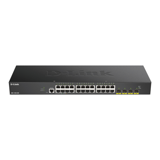
D-Link DGS-1250 Series Hardware Installation Manual
Gigabit ethernet smart managed switches
Hide thumbs
Also See for DGS-1250 Series:
- Hardware installation manual (54 pages) ,
- Reference manual (312 pages) ,
- Reference manual (34 pages)
Table of Contents
Advertisement
Advertisement
Table of Contents


Need help?
Do you have a question about the DGS-1250 Series and is the answer not in the manual?
Questions and answers