Table of Contents
Advertisement
Advertisement
Table of Contents

Related Manuals for D-Link DGS-1510-20


Summary of Contents for D-Link DGS-1510-20
- Page 2 Information in this document is subject to change without notice. Reproduction in any manner whatsoever, without the written permission of D-Link Corporation, is strictly forbidden. Trademarks used in this text: D-Link and the D-LINK logo are trademarks of D-Link Corporation; Microsoft and Windows are registered trademarks of Microsoft Corporation.
-
Page 3: Table Of Contents
DGS-1510 Series Gigabit Ethernet SmartPro Switch Hardware Installation Guide Table of Contents Intended Readers ................................ v Typographical Conventions ............................v Notes, Notices, and Cautions ............................v Safety Instructions ..............................vi Safety Precautions ..............................vi General Precautions for Rack-Mountable Products ....................vii Protecting Against Electrostatic Discharge ........................ - Page 4 DGS-1510 Series Gigabit Ethernet SmartPro Switch Hardware Installation Guide Physical and Environmental............................40 Performance................................42 LED Indicators ................................44 Per Switch ................................44 Per RJ45 Port ............................... 44 Per SFP Port ................................. 45 Per SFP+ Port ............................... 45 Port Functions ................................45 Appendix B –...
-
Page 5: Intended Readers
DGS-1510 Series Gigabit Ethernet SmartPro Switch Hardware Installation Guide Intended Readers Intended Readers Typographical Conventions Notes, Notices, and Cautions Safety Instructions General Precautions for Rack-Mountable Products Protecting Against Electrostatic Discharge The DGS-1510 Series Hardware Installation Guide contains information about the configuration and management of the switch. -
Page 6: Safety Instructions
DGS-1510 Series Gigabit Ethernet SmartPro Switch Hardware Installation Guide Safety Instructions Use the following safety guidelines to ensure your own personal safety and to help protect your system from potential damage. Throughout this safety section, the caution icon ( ) is used to indicate precautions that need to be reviewed and followed. -
Page 7: General Precautions For Rack-Mountable Products
DGS-1510 Series Gigabit Ethernet SmartPro Switch Hardware Installation Guide • Do not modify power cables or plugs. Consult a licensed electrician or your power company for site modifications. Always follow your local/national wiring rules. • When connecting or disconnecting power to hot-pluggable power supplies, if offered with your system, observe the following guidelines: o Install the power supply before connecting the power cable to the power supply. -
Page 8: Protecting Against Electrostatic Discharge
DGS-1510 Series Gigabit Ethernet SmartPro Switch Hardware Installation Guide Protecting Against Electrostatic Discharge Static electricity can harm delicate components inside the system. To prevent static damage, discharge static electricity from your body before touching any of the electronic components, such as the microprocessor. -
Page 9: Introduction
Series. When referring to these universal features, we will simply refer to the product as the Switch. Package Contents When purchasing a D-Link DGS-1510 Series Switch, a list of items will be included in the package of the Switch. Open the shipping carton of the Switch and carefully unpack its contents. The carton should contain the following items: •... - Page 10 • Supports Port Security of up to 128 MAC addresses. • Supports Broadcast and Multicast Storm Control. • Supports Traffic Segmentation • Supports D-Link SafeGuard Engine. • Supports ARP Spoofing Prevention. • Supports IP-MAC-Port Binding (IMPB). This feature includes DHCP Snooping, IP Source Guard, Dynamic ARP Inspection, DHCPv6 Guard, RA Guard, IPv6 Snooping, IPv6 Source Guard, and IPv6 ND Snooping.
-
Page 11: Front-Panel Components
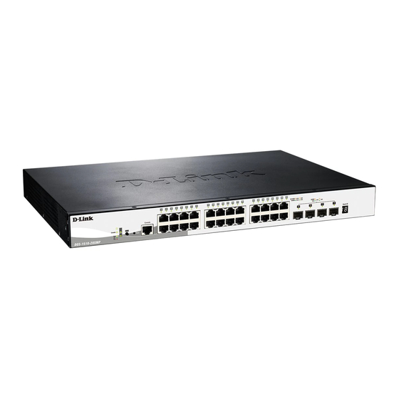
On the front panel of the Switch there are Ethernet RJ45/SFP/SFP+ ports, a Console port, a Reset button, a Mode button (only of PoE supported switches), and LED indicators. Figure 1-1 Front panel view of a DGS-1510-20 Switch Figure 1-2 Front panel view of a DGS-1510-28 Switch... -
Page 12: Ports
Figure 1-9 Front panel view of a DGS-1510-52XMP Switch Ports The Type and Number of ports available on the Switch are listed out below: • DGS-1510-20: o Sixteen Copper Ports (10BASE-T/100BASE-TX/1000BASE-T), o Two SFP Ports (1000BASE), o Two Dual Speed SFP+ Ports (1000BASE/10GBASE), o One Console Port (RJ-45), •... -
Page 13: Reset Button
ID and Link/Act indicators for all the ports. The DGS-1510-28P, DGS-1510-28XMP, and DGS-1510- 52XMP switches are equipped with an additional PoE light, to indicate whether the ports are running in Power over Ethernet mode. Figure 1-10 LED indicators for a DGS-1510-20 Switch... - Page 14 DGS-1510 Series Gigabit Ethernet SmartPro Switch Hardware Installation Guide Figure 1-11 LED indicators for a DGS-1510-28 Switch Figure 1-12 LED indicators for a DGS-1510-28P Switch Figure 1-13 LED indicators for a DGS-1510-28X Switch Figure 1-14 LED indicators for a DGS-1510-28XMP Switch Figure 1-15 LED indicators for a DGS-1510-52 Switch Figure 1-16 LED indicators for a DGS-1510-52X (HW: A1) Switch...
- Page 15 DGS-1510 Series Gigabit Ethernet SmartPro Switch Hardware Installation Guide Figure 1-17 LED indicators for a DGS-1510-52X (HW: A2) Switch Figure 1-18 LED indicators for a DGS-1510-52XMP Switch A separate table below describes LED indicators in more detail. Description This LED will light green after powering the Switch on to indicate the Power ready state of the device.
-
Page 16: Rear Panel Components
On the rear panel of the Switch there are an AC power socket, an electrical grounding point, and a security lock. Figure 1-19 Rear panel view of a DGS-1510-20 Switch Figure 1-20 Rear panel view of a DGS-1510-28 Switch Figure 1-21 Rear panel view of a DGS-1510-28P Switch... -
Page 17: Side Panel Components
Leave at least 6 inches of space at the rear and sides of the Switch for proper ventilation. Without proper heat dissipation and air circulation, system components might overheat which could lead to system failure or even severely damaged components. Figure 1-28 Side panels view of a DGS-1510-20 Switch... - Page 18 DGS-1510 Series Gigabit Ethernet SmartPro Switch Hardware Installation Guide Figure 1-29 Side panels view of a DGS-1510-28 Switch Figure 1-30 Side panels view of a DGS-1510-28P Switch Figure 1-31 Side panels view of a DGS-1510-28X Switch Figure 1-32 Side panels view of a DGS-1510-28XMP Switch...
-
Page 19: Smart Fans
DGS-1510 Series Gigabit Ethernet SmartPro Switch Hardware Installation Guide Figure 1-33 Side panels view of a DGS-1510-52 Switch Figure 1-34 Side panels view of a DGS-1510-52X (HW: A1) Switch Figure 1-35 Side panels view of a DGS-1510-52X (HW: A2) Switch Figure 1-36 Side panels view of a DGS-1510-52XMP Switch Smart Fans The DGS-1510 Series Switches includes smart fans that will automatically change their speed... - Page 20 DGS-1510 Series Gigabit Ethernet SmartPro Switch Hardware Installation Guide The following will explain at what temperature the speed of the fan(s) will change: • DGS-1510-20: The fan speed will change from: Low Speed to High Speed at 48.0°C. High Speed to Low Speed at 43.0°C.
-
Page 21: Installation
DGS-1510 Series Gigabit Ethernet SmartPro Switch Hardware Installation Guide 2. Installation Installation Guidelines Power On (AC Power) Installation Guidelines Please follow these guidelines for setting up the Switch: • Install the Switch on a sturdy, level surface that can support at least 6 kg (13.2 lb). Do not place heavy objects on the Switch. -
Page 22: Installing The Switch In A Standard 19" Rack
DGS-1510 Series Gigabit Ethernet SmartPro Switch Hardware Installation Guide Figure 2-2 Attach mounting brackets to the Switch Fasten the mounting brackets to the Switch using the screws provided. With the brackets attached securely, the Switch can be mounted in a standard rack, as shown below. NOTE: Please review the Installation Guidelines above before installing the Switch in a rack. -
Page 23: Power On (Ac Power)
DGS-1510 Series Gigabit Ethernet SmartPro Switch Hardware Installation Guide can be uplinked with various other switches across a gigabit network. The SFP ports support data rates of up to 1Gbit/s and the SFP+ ports support data rates of up to 10Gbit/s. See the figure below for installing the transceiver in the transceiver port on the Switch. -
Page 24: Installing Power Cord Clip
DGS-1510 Series Gigabit Ethernet SmartPro Switch Hardware Installation Guide Installing Power Cord Clip To prevent accidental removal of the AC power cord, it is recommended to install the power cord clip together with the power cord. NOTE: The DGS-1510-52XMP does not support the installation of the power cord clip. With the rough side facing down, insert the Tie Wrap into the hole below the power socket. - Page 25 DGS-1510 Series Gigabit Ethernet SmartPro Switch Hardware Installation Guide Slide the Retainer through the Tie Wrap until the end of the cord. Figure 2-7 Slide the Retainer through the Tie Wrap Circle the tie of the Retainer around the power cord and into the locker of the Retainer. Figure 2-8 Circle around the power cord...
- Page 26 DGS-1510 Series Gigabit Ethernet SmartPro Switch Hardware Installation Guide Fasten the tie of the Retainer until the power cord is secured. Figure 2-9 Secure the power cord...
-
Page 27: Installing The Rps Into A Rack-Mount Chassis
DGS-1510 Series Gigabit Ethernet SmartPro Switch Hardware Installation Guide Installing the RPS into a Rack-mount Chassis The DPS-700 is a redundant power supply unit designed to conform to the voltage requirements of the switches being supported. The DPS-700 can only be used with the DGS-1510-52XMP. CAUTION: DO NOT connect the RPS to AC power before the DC power cable is connected. - Page 28 DGS-1510 Series Gigabit Ethernet SmartPro Switch Hardware Installation Guide Figure 2-11 Rear view of the DPS-700 connected to a DGS-1510-52XMP CAUTION: Do not connect the DPS-700 to the DGS-1510-52XMP by using the 14-pin DC power cable. It may cause damage when using the wrong DC power cable.
-
Page 29: Connecting The Switch
DGS-1510 Series Gigabit Ethernet SmartPro Switch Hardware Installation Guide 3. Connecting the Switch Switch to End Node Switch to another Switch Switch to a Server Switch to End Node An End Node can be any networking device, plugged into any of the networking ports of the Switch, where data transmission ends. -
Page 30: Switch To A Server
DGS-1510 Series Gigabit Ethernet SmartPro Switch Hardware Installation Guide Switch to a Server The Combo Copper/SFP ports are ideal for connecting a network backbone, server or server farm to the Switch. The copper ports operate at a speed of 10/100/1000Mbps in half-duplex or full-duplex mode. -
Page 31: Introduction To Switch Management
DGS-1510 Series Gigabit Ethernet SmartPro Switch Hardware Installation Guide 4. Introduction to Switch Management Management Options Connecting the Console Port SNMP Settings Management Options This Switch can be managed, out-of-band, through the console port on the front panel or in-band using Telnet. - Page 32 DGS-1510 Series Gigabit Ethernet SmartPro Switch Hardware Installation Guide o The Parity should be None. o The Stop bits should be 1. o The Flow control should be None. Figure 4-1 HyperTerminal Connection Properties • Now the Switch can be turned on and access to the Switch’s CLI will be available. NOTE: Access to the console port can be made at any time while the Switch is on.
-
Page 33: Connecting To The Switch For The First Time
Enter the username and password when prompt to do so and press enter after each entry. The CLI prompt will immediately be available, as shown below. DGS-1510-28XMP Gigabit Ethernet SmartPro Switch Command Line Interface Firmware: Build 1.50.020 Copyright(C) 2018 D-Link Corporation. All rights reserved. User Access Verification Username:admin Password:***** Switch#... -
Page 34: Creating A User Account
DGS-1510 Series Gigabit Ethernet SmartPro Switch Hardware Installation Guide CAUTION: For security reasons, it is highly recommended to configure a personal username and password for this Switch. Creating a User Account This section will discuss how to create a login username and password on this Switch. This login details will be applied not only for access to the CLI, but also for access to the Web UI, Telnet, SSH, and SSL interfaces. -
Page 35: Snmp Settings
DGS-1510 Series Gigabit Ethernet SmartPro Switch Hardware Installation Guide To find out what the IP address of the Switch is, we again need to access the Switch management interface through the CLI. Take note of the following example. Switch> show ip interface Interface vlan1 is enabled, Link status is down IP Address is 10.90.90.90/8 (Manual) ARP timeout is 20 minutes. -
Page 36: Traps
MIB-II, the Switch also supports its own proprietary enterprise MIB as an extended Management Information Base. The proprietary MIB may also be retrieved by specifying the MIB Object Identifier. MIB values can be either read-only or read-write. NOTE: For customers interested in D-View, D-Link Corporation's proprietary SNMP management software, go to http://dview.dlink.com.tw/ and download the software and manual. -
Page 37: Web-Based Switch Configuration
DGS-1510 Series Gigabit Ethernet SmartPro Switch Hardware Installation Guide 5. Web-based Switch Configuration Introduction Logging onto the Web Manager Web-based User Interface Introduction Most software functions of the Switch can be managed, configured, and monitored via the embedded Web User Interface (Web UI). Manage the Switch from remote stations anywhere on the network through a standard browser, such as Internet Explorer (version 7 and later), Mozilla Firefox, Chrome, or Safari. -
Page 38: Web-Based User Interface
Some management functions like port monitoring are also accessible here. Click the D-Link logo to go to the D-Link website. AREA 2 In this area is a toolbar used to access functions like Save, Tools, the Wizard, Online Help, accessing the Web UI in the Surveillance Mode, customized Language preference, and a Logout option. - Page 39 DGS-1510 Series Gigabit Ethernet SmartPro Switch Hardware Installation Guide Area Number Description There is also a search option in this area that can be used to search for specific feature keywords in the Web UI to find the link to the set of features.
-
Page 40: Appendix A - Technical Specifications
UTP/STP Category.5, 5 Enhanced for 100BASE-TX EIA/TIA-568 100Ω screened twisted-pair (STP) (100m) Physical and Environmental Feature Detailed Description Internal Power Supply DGS-1510-20: 100-240 VAC, 50/60 Hz, 24 Watt DGS-1510-28: 100-240 VAC, 50/60 Hz, 30 Watt DGS-1510-28P: 100-240 VAC, 50/60 Hz, 253 Watt... - Page 41 100-240 VAC, 50/60 Hz, 589 Watt Fans The IC Sensor detects the temperature on the switch automatically, and adjusts the speed. The amount of fans that are installed per Switch are listed below: DGS-1510-20: 1 fan DGS-1510-28: 1 fan DGS-1510-28P:...
-
Page 42: Performance
CE Class A, FCC Class A, VCCI Report Class A, C-Tick Report Class A, BSMI, CCC. Safety Certifications and UL/CSA 60950-1, IEC 60950-1:2001, BSMI. Test Reports Performance Feature Detailed Description Transmission Method Store-and-forward Packet Buffer DGS-1510-20/28/28P/28X/28XMP: 1.5 MB per device... - Page 43 • Up to 6 units per stack • Backup master • Inter-stacking trunking and mirroring Virtual Stacking / Clustering Supports the following: • D-Link Single IP Management version 1.6 • Manage up to 32 devices in a virtual stack with a single IP address...
-
Page 44: Led Indicators
DGS-1510 Series Gigabit Ethernet SmartPro Switch Hardware Installation Guide LED Indicators Per Switch LED Indicator Color Status Description Power Green Solid light Power on Blinking Performing System Self-test Light off Power off Console Green Solid light Console on Light off Console off Green Solid light... -
Page 45: Per Sfp Port
DGS-1510 Series Gigabit Ethernet SmartPro Switch Hardware Installation Guide LED Indicator Color Status Description DGS-1510- Light off No power feeding 28XMP, and DGS-1510- 52XMP Only) Per SFP Port LED Indicator Color Status Description Link/Act Green Solid light When there is a secure connection (or link) to 1000Mbps Ethernet device at any of the ports Blinking When there is reception or transmission of data... - Page 46 DGS-1510 Series Gigabit Ethernet SmartPro Switch Hardware Installation Guide Feature Detailed Description • DEM-310GT (1000BASE-LX, Single-mode, 10 km) • DEM-311GT (1000BASE-SX, Multi -mode, 550 m) • DEM-312GT2 (1000BASE-SX, Multi-mode, 2 km) • DEM-314GT (1000BASE-LHX, Single-mode, 50 km) • DEM-315GT (1000BASE-ZX, Single-mode, 80 km) •...
- Page 47 3, 6A UTP cable for 802.3af or Category 5e, 6A UTP cable for 802.3at • The PoE switch works with all D-Link 802.3af and 802.3at capable devices and with all non-802.3af and non-802.3at capable D-Link Access Points, IP Cameras and IP Phones •...
-
Page 48: Appendix B - Cables And Connectors
DGS-1510 Series Gigabit Ethernet SmartPro Switch Hardware Installation Guide Appendix B – Cables and Connectors Ethernet Cable When connecting the Switch to another switch, a bridge or hub, a normal cable is necessary. Please review these products for matching cable pin assignment. The following diagrams and tables show the standard RJ-45 connector and their pin assignments. -
Page 49: Console Cable
DGS-1510 Series Gigabit Ethernet SmartPro Switch Hardware Installation Guide Console Cable When connecting the Switch to a PC, a Console cable is necessary. The following diagrams and tables show the standard Console-to-DJ-45 receptacle/connector and their pin assignments. Figure B–2 Console-to-RJ-45 Cable Console-to-RJ-45 PIN Assignments: Console (DB9/RS232) RJ-45... -
Page 50: Redundant Power Supply (Rps) Cable
DGS-1510 Series Gigabit Ethernet SmartPro Switch Hardware Installation Guide Redundant Power Supply (RPS) Cable When connecting the Switch to a Redundant Power Supply, an RPS cable is necessary. Please review these products for matching cable pin assignment. The following diagrams and tables show the standard RPS receptacle/connector and their pin assignments. - Page 51 DGS-1510 Series Gigabit Ethernet SmartPro Switch Hardware Installation Guide +12VRTNsen +12VRTNsen LS+12V LS+12V -54Vsen -54Vsen -54VRTNsen -54VRTNsen...
-
Page 52: Appendix C - Erps Information
Appendix C – ERPS Information Only hardware-based ERPS (external PHY) supports the Fast Link Drop Interrupt feature with a recovery time of 50ms. Model Name ERPS Port 1 to 20 DGS-1510-20 Hardware-based Software-based Model Name ERPS Port 1 to 8... -
Page 53: Warranties & Technical Support
The customer must submit with the product as part of the claim a written description of the Hardware defect or Software nonconformance in sufficient detail to allow D-Link to confirm the same, along with proof of purchase of the product (such as a copy of the dated purchase invoice for the product) if the product is not registered. - Page 54 D-Link Corporation/D-Link Systems, Inc., as stipulated by the United States Copyright Act of 1976 and any amendments thereto. Contents are subject to change without prior notice. Copyright 2004 by D-Link Corporation/D-Link Systems, Inc.
- Page 55 Product Registration Register your D-Link product online at http://support.dlink.com/register/ Product registration is entirely voluntary and failure to complete or return this form will not diminish your warranty rights.
- Page 56 This guide is only for initial configuration. Please refer to the user manual to learn more or visit http://www.mydlink.com for more information. Also feel free to contact us. U.S. and Canadian customers can contact D-Link Technical Support through our website. http://support.dlink.com Canada...
- Page 57 Europe customers TECHNICAL SUPPORT TECHNISCHE UNTERSTÜTZUNG ASSISTANCE TECHNIQUE ASISTENCIA TÉCNICA SUPPORTO TECNICO TECHNISCHE ONDERSTEUNING POMOC TECHNICZNA TECHNICKÁ PODPORA TECHNICKÁ PODPORA dlink.com/support TECHNIKAI TÁMOGATÁS TEKNISK SUPPORT TEKNISK SUPPORT TEKNISK STØTTE TEKNINEN TUKI ASSISTÊNCIA TÉCNICA ΤΕΧΝΙΚΉ ΥΠΟΣΤΉΡΙΞΗ TEHNIČKA PODRŠKA TEHNIČNA PODPORA SUPORT TEHNIC ТЕХНИЧЕСКА...
- Page 58 Indonesia - www.dlink.co.id Malaysia - www.dlink.com.my Philippines - www.dlink.com.ph Vietnam - www.dlink.com.vn Korea customers Tel : +82-2-2028-1810 Monday to Friday 9:00am to 6:00pm Web : http://d-link.co.kr E-mail : g2b@d-link.co.kr New Zealand customers Tel: 0800-900-900 24/7 Technical Support Web: http://www.dlink.co.nz E-mail: support@dlink.co.nz...
- Page 59 08600 DLINK (for South Africa only) Monday to Friday 8:30am to 9:00pm South Africa Time Web: http://www.d-link.co.za E-mail: support@za.dlink.com D-Link Middle East - Dubai, U.A.E. customers Plot No. S31102, Jebel Ali Free Zone South, P.O.Box 18224, Dubai, U.A.E. Tel: +971-4-8809022...
- Page 60 Pakistan customers Islamabad Office: 61-A, Jinnah Avenue, Blue Area, Suite # 11, EBC, Saudi Pak Tower, Islamabad - Pakistan Tel.: +92-51-2800397, 2800398 Fax: +92-51-2800399 Karachi Office: D-147/1, KDA Scheme # 1, Opposite Mudassir Park, Karsaz Road, Karachi – Pakistan Phone: +92-21-34548158, 34326649 Fax: +92-21-4375727 Technical Support: +92-21-34548310, 34305069 General Inquiries: info.pk@me.dlink.com...
- Page 61 Lebanon RMA center customers Dbayeh/Lebanon PO Box:901589 Tel: +961 4 54 49 71 Ext:14 Fax: +961 4 54 49 71 Ext:12 Email: taoun@me.dlink.com Bahrain customers Technical Support: +973 1 3332904 Kuwait customers Technical Support: + 965 22453939 / +965 22453949...
- Page 62 Обновления программного обеспечения и документация доступны на Интернет-сайте D-Link. D-Link предоставляет бесплатную поддержку для клиентов в течение гарантийного срока. Клиенты могут обратиться в группу технической поддержки D-Link по телефону или через Интернет. Техническая поддержка компании D-Link работает в круглосуточном режиме ежедневно, кроме официальных праздничных дней. Звонок...
- Page 63 Офисы Россия Հայաստան Москва, Графский переулок, 14 Երևան, Դավթաշեն 3-րդ Тел. : +7 (495) 744-00-99 թաղամաս, 23/5 E-mail: mail@dlink.ru Հեռ.՝ +374 (10) 39-86-67 Էլ. փոստ՝ info@dlink.am Україна Київ, вул. Межигірська, 87-А Latvija Тел.: +38 (044) 545-64-40 Rīga, Lielirbes iela 27 E-mail: ua@dlink.ua Tel.: +371 (6) 761-87-03 E-mail: info@dlink.lv...
- Page 64 Soporte Técnico Para Usuarios En Latino America Por favor revise el número telefónico del Call Center de su país en http://www.dlinkla.com/soporte/call-center Soporte Técnico de D-Link a través de Internet Horario de atención Soporte Técnico en www.dlinkla.com e-mail: soporte@dlinkla.com & consultas@dlinkla.com...
- Page 65 Clientes de Brasil Caso tenha dúvidas na instalação do produto, entre em contato com o Suporte Técnico D-Link. Acesse o site: www.dlink.com.br/suporte...
- Page 66 台灣服務時間:週一至週五 : 9:00~21:00 週六日及國定假日 ( 不含農曆春節 ) 10:00~19:00 台灣網站: http://www.dlink.com.tw 台灣電子郵件: dssqa_service@dlink.com.tw 產品保固期限、台灣區維修據點查詢,請參考 http://www.dlink.com.tw 網頁說明。 香港、澳門 D-Link 技術諮詢專線 香港技術諮詢服務專線 (852) 8100 8892 香港服務時間:週一至週五 9:00AM~1:00PM 及 2:00PM~6:00PM 週六 9:00AM~1:00PM 香港網站: http://www.dlink.com.hk 香港電子郵件: service@cn.synnex-grp.com 香港、澳門維修據點查詢請參考 http://www.dlink.com.hk/contact.html 網頁說明 如果您是其他地區的用戶,請參考 D-Link 網站 www.dlink.com 查詢全球各地分公司的聯絡 資訊以取得相關支援服務。...
- Page 67 Pelanggan Indonesia Update perangkat lunak dan dokumentasi pengguna dapat diperoleh pada situs web D-Link. Dukungan Teknis untuk pelanggan: Tel: 0800-14014-97 (Layanan Bebas Pulsa) Dukungan Teknis D-Link melalui Internet: Pertanyaan Umum: sales@id.dlink.com Bantuan Teknis: support@id.dlink.com Website : http://www.dlink.co.id 日本のお客様 この度は弊社製品をお買い上げいただき、誠にありがとうございます。 製品に同梱されている保証書の購入元にお問い合わせください。...
- Page 68 8. What category best describes your company? Aerospace Engineering Education Finance Hospital Legal Insurance/Real Estate Manufacturing Retail/Chain store/Wholesale Government Transportation/Utilities/Communication System house/company Other________________________________ 9. Would you recommend your D-Link product to a friend? Don't know yet 10.Your comments on this product? __________________________________________________________________________________________ __________________________________________________________________________________________...
Need help?
Do you have a question about the DGS-1510-20 and is the answer not in the manual?
Questions and answers