Elation Design LED 36 Brick Manual
Led fixture
Hide thumbs
Also See for Design LED 36 Brick:
- Technical specifications (3 pages) ,
- Brochure & specs (3 pages)

Related Manuals for Elation Design LED 36 Brick


Summary of Contents for Elation Design LED 36 Brick
- Page 1 Design LED 36 Brick Elation Professional™ 6122 S. Eastern Ave. Los Angeles, Ca 90040 www.elationlighting.com Rev. 1/4/2010 – visage...
-
Page 2: Table Of Contents
DESIGN LED 36 BRICK™ TABLE OF CONTENS General Information……………………………………………………………………… 2 a. Introduction………………………………………………………………………. 2 b. Unpacking………………………………………………………..…...………..… 2 c. Customer Support…………………………………………….………………… 2 d. Warranty Registration……………………………………………….……..…… 3 Safety Instructions………………………………………………………..…………. 4 Features…………………………………………………………………………………… 6 General Guidelines………………………………………………………………………. 7 Fixture Overview…………………………………………………………………………. 8 Mounting and Installation…………………………………………………….…….……. 10 a. Yoke Assembly…………………………………………………….……………..10 b. -
Page 3: General Information
INTRODUCTION: Congratulations, you have just purchased one of the most innovative and reliable LED fixtures on the market today! The Design LED 36 Brick,™ has been designed to perform reliably for years when the guidelines in this booklet are followed. Please read and understand the instructions in this manual carefully and thoroughly before attempting to operate this unit. -
Page 4: Warranty Registration
Please do not discard the shipping carton in the trash. Please recycle whenever possible. WARRANTY REGISTRATION: The Design LED 36 Brick™ carries a two year (730 days) limited warranty. Please fill out the enclosed warranty card to validate your purchase. All returned service items whether under warranty or not, must be freight pre-paid and accompany a return authorization (R.A.) number. -
Page 5: Safety Instructions
4. For safe operation, follow the Installation guide described in chapter two of this manual. Operating the Design LED 36 Brick™ without suited safety aids such as safety cables or clamps can increase the risk of damage and/or personal injury. - Page 6 DESIGN LED 36 BRICK™ sure the power cord is never crimped or damaged. If the power cord is damaged, replace it immediately with a new one of similar power rating. 13. Always disconnect from main power before performing any type of service or any cleaning procedure.
-
Page 7: Features
DESIGN LED 36 BRICK™ 3. FEATURES • 25˚ Lens Kit Standard (14˚ Beam Angle) • 45˚ Optional Lens Kit (15˚ Beam Angle) • Minimal heat emission • Maintenance free operation • Equipped with 12 3-Watt LEDs (4 x Red, 4 x Green, 4 x Blue) •... -
Page 8: General Guidelines
DESIGN LED 36 BRICK™ 4. GENERAL GUIDELINES This fixture is a professional lighting effect designed for use on stage, in nightclubs, in theatres, and other types of architectural installations. Do not attempt operation or installation without a proper knowledge on how to do so. -
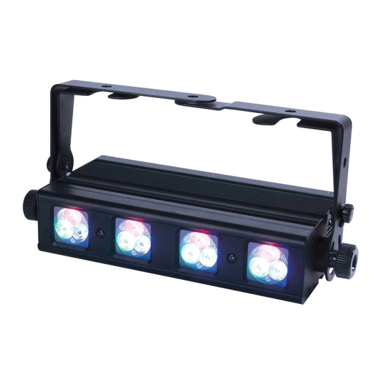
Page 9: Fixture Overview
3. Hanging Bracket Locking Knob – This knob is used to secure the hanging bracket in to place. 4. On/Off Power Switch – Controls main power to the unit. 5. Power Output Jack – Use this jack to jump power to another Design LED 36 Brick™ ©Elation Professional, Los Angeles Ca. www.ElationLighting.com... - Page 10 IEC connector for power. If needed, always replace fuse with an exact match unless otherwise specified by an Elation Service Technician. Using a fuse other than that specified could damage the unit and will void your warranty.
-
Page 11: Mounting And Installation
DESIGN LED 36 BRICK™ 6. MOUNTING AND INSTALLATION Yoke Assembly – Single Unit Operation The device can be placed directly on the stage floor or rigged in any orientation on a truss without altering its operation characteristics. When connecting the hanging yoke to the fixture, refer to the illustration below. -
Page 12: Mounting Points
DESIGN LED 36 BRICK™ Please note: To ensure maximum stability, no more than for units should be mounted together in this fashion. Connecting more than four units will result in an unstable assembly, which could collapse and damage the units. -
Page 13: Mounting Positions
DESIGN LED 36 BRICK™ power cord to the appropriate wall outlet. Mounting The Design LED Brick™ is fully operational in any mounting position, hanging upside-down from a ceiling, side mounted, or set on a flat level surface, etc. Be sure this fixture is kept at least 0.5m away from any flammable materials (decoration etc.). - Page 14 DESIGN LED 36 BRICK™ please refer to the safety guidelines in this manual to avoid damage to the unit and/or injury to persons. When mounting this fixture to truss be sure to secure an appropriately rated clamp to the hanging yoke using a M10 screw fitted through the center hole of the hanging yoke. As an added safety measure be sure to attach at least one properly rated safety cable to the fixture.
-
Page 15: Securing
DESIGN LED 36 BRICK™ Securing the Design LED Brick™ Always be sure to secure your fixture with a safety cable when suspending the unit from truss or other means. The fixture provides a built-in rigging point for a safety cable as illustrated above. -
Page 16: Understanding Dmx
1 to that fixture no matter where it is located in the DMX chain. The Design LED 36 Brick™ can be controlled via DMX-512 protocol. The Design LED 36 Brick™ is a fixture that can operate in five different DMX modes; 3, 5, 6, 12, or 15 channels (see page 22 for the different DMX operations). -
Page 17: Dmx Connections
XLR input and output connectors. Always be sure daisy chain your in and out data connections, never split or “Y” your DMX connections unless you are using an approved DMX splitter such as the Elation Opto Branch 4™ or DMX Branch/4™. ©Elation Professional, Los Angeles Ca. -
Page 18: Dmx Terminator
2 and 3 of a male XLR connector (DATA + and DATA -). This fixture is inserted in the female XLR connector of the last fixture in your daisy chain to terminate the line. Using a line terminator (Elation part: DMX T PACK) will decrease the possibilities of erratic behavior. - Page 19 In the case of the Design LED 36 Brick™, which is up to a 15 channel fixture, you should set the starting DMX address of the first unit to 1, the second unit to 16 (15 + 1), the third unit to 31 (15 + 16), and so on.
-
Page 20: Fixture Menu
DESIGN LED 36 BRICK™ 8. FIXTURE MENU Default settings shaded. ADDR AXXX (1-512) Set the starting DMX address Display “Blackout” function. When activated the display DISP ON/OFF will automatically blackout when not in use. FLIP ON/OFF When “ON” this function rotate the display 180°... - Page 21 DESIGN LED 36 BRICK™ SPED Adjust program 4 speed FADE Adjust program 4 fade time CHS4 STRB Adjust strobe rate of program 4 SPED Adjust program 5 speed CHS5 FADE Adjust program 5 fade time STRB Adjust strobe rate of program 5...
-
Page 22: Dmx Traits
DESIGN LED 36 BRICK™ 9. DMX TRAITS DMX Operation Notes: The fixture will function in DMX mode whenever the unit is receiving a DMX signal. Please note that this will override all manual settings. This unit will keep and retain the last DMX command in the event of DMX signal failure. To reset the fixture you must turn the power off. -
Page 23: 4-Channel Mode
DESIGN LED 36 BRICK™ 4-Channel mode: In this mode channel 1 controls all the red LEDs, channel 2 controls all the green LEDs, channels 3 controls all the blue LEDs, and channel 4 will control the master dimming level. CHANNEL 1:Red... -
Page 24: 6-Channel Mode
DESIGN LED 36 BRICK™ 6 Channel Mode: This chart details a simple layout of the DMX channel assignment in CHANNEL 1: Red CHANNEL 2: Green CHANNEL 3: Blue CHANNEL 4: Auto Programs (Built-in Programs) CHANNEL 5: Strobe CHANNEL 6: Dimmer/Speed DMX channel’s functions and their values (6 Channel Mode):... -
Page 25: 12-Channel Mode
DESIGN LED 36 BRICK™ 1~95 Strobe effect slow to fast 96-127 No function 128-159 Pulse effect in sequences 160-191 No function 192-223 Random strobe effect slow to fast 224-255 No function Channel 6 - General dimming / Program Speed Control This channel has two functions depending on the operating mode. - Page 26 DESIGN LED 36 BRICK™ 12-Channel mode: In this mode all channels are used to control the various RGB LEDs. CHANNEL 1:Red CHANNEL 2:Green CHANNEL 3:Blue CHANNEL 4:Red CHANNEL 5:Green CHANNEL 6:Blue CHANNEL 7:Red CHANNEL 8:Green CHANNEL 9:Blue CHANNEL 10:Red CHANNEL 11:Green...
- Page 27 DESIGN LED 36 BRICK™ 0-255 Green (0-Black, 255- 100% Green) Channel 6 - Blue: 221-255 Blue (0-Black, 255- 100% Blue) Channel 7 - Red: 0-255 Red (0-Black, 255-100% Red) Channel 8 - Green: 0-255 Green (0-Black, 255- 100% Green) Channel 9 - Blue:...
-
Page 28: 15-Channel Mode
DESIGN LED 36 BRICK™ 15-Channel mode: In this mode channels 1~12 are used to control the various RGB LEDs and channels 13~15 will control special features. CHANNEL 1:Red CHANNEL 2:Green CHANNEL 3:Blue CHANNEL 4:Red CHANNEL 5:Green CHANNEL 6:Blue CHANNEL 7:Red... - Page 29 DESIGN LED 36 BRICK™ DMX channel’s functions and their values (15 Channel Mode): Channel 1 - Red: 0-255 Red (0-Black, 255-100% Red) Channel 2 - Green: 0-255 Green (0-Black, 255- 100% Green) Channel 3 - Blue: 0-255 Blue (0-Black, 255- 100% Blue)
- Page 30 DESIGN LED 36 BRICK™ Channel 11 - Green: 0-255 Green (0-Black, 255- 100% Green) Channel 12 - Blue: 0-255 Blue (0-Black, 255- 100% Blue) Channel 13 - Internal programs: 0-10 No function 11-40 Internal program 1 41-70 Internal program 2...
-
Page 31: Lens Replacement
DESIGN LED 36 BRICK™ 10. LENS REPLACEMENT The Design LED 36 Brick comes with a removable front cover that allows lens assembly to be changed out to achieve different beam angles. The lens cover is held in place by two ¼ turn locking fasteners. To remove the cover; 1) Turn the locking fasteners in a counter-clockwise direction. -
Page 32: Cleaning And Maintenance
DESIGN LED 36 BRICK™ 11. CLEANING AND MAINTENANCE Consider the following points during normal service and inspection: 1. Be sure all screws and fasteners are securely tightened at all times. Lose screws may fall out during normal operation resulting in damage or injury as larger parts could fall. -
Page 33: Warranty
® defective parts at its expense, and will absorb all expenses for warranty service and repair labor by reason of defects in material or workmanship. The sole responsibility of Elation Professional under this warranty shall be limited to the repair of the product, or replacement ®... - Page 34 The consumer’s and or Dealer’s sole remedy shall be such repair or replacement as is expressly provided above; and under no circumstances shall Elation Professional® be liable for any loss or damage, direct or consequential, arising out of the use of, or inability to use, this product.
-
Page 35: Photometric Data
DESIGN LED 36 BRICK™ PHOTOMETRIC DATA ©Elation Professional, Los Angeles Ca. www.ElationLighting.com... - Page 36 DESIGN LED 36 BRICK™ ©Elation Professional, Los Angeles Ca. www.ElationLighting.com...
-
Page 37: Dimensional Drawings
DESIGN LED 36 BRICK™ DIMENSIONAL DRAWINGS ©Elation Professional, Los Angeles Ca. www.ElationLighting.com... -
Page 38: Circuit Schematic
DESIGN LED 36 BRICK™ CIRCUIT SCHEMATIC ©Elation Professional, Los Angeles Ca. www.ElationLighting.com... -
Page 39: Technical Specifications
DESIGN LED 36 BRICK™ TECHNICAL SPECIFICATIONS Power supply: 100v~240v / 50Hz~60Hz AC Power consumption: MAXIMUM 65W LED Configuration: 12 x 3 Watt IP Rating: IP20 Weight: 4.3 Kgs / 9.5Lbs DMX Channels: 15, 12, 6, 4, or 3 Channel mode... - Page 40 Elation Professional 6122 S. Eastern Ave. Los Angeles, CA. 90040 323-582-3322 / 323-832-9142 fax www.ElationLighting.com / Info@ElationLighitng.com Rev. 1/4/2010 – visage...
Need help?
Do you have a question about the Design LED 36 Brick and is the answer not in the manual?
Questions and answers