Sign In
Upload
Download
Table of Contents
Contents
Add to my manuals
Delete from my manuals
Share
URL of this page:
HTML Link:
Bookmark this page
Add
Manual will be automatically added to "My Manuals"
Print this page
×
Bookmark added
×
Added to my manuals
Manuals
Brands
Amana Manuals
Oven
AXP Series
Service training manual
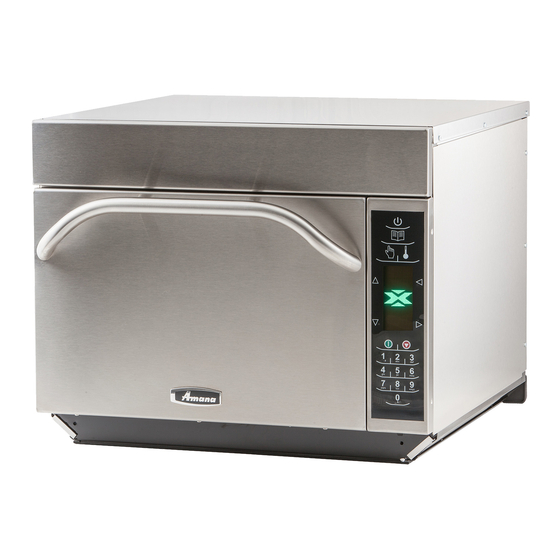
Amana AXP Series Service Training Manual
High speed combination oven
Hide thumbs
1
2
3
4
5
6
7
8
9
10
11
12
13
14
15
16
17
18
19
20
21
22
23
24
25
26
27
28
29
30
31
32
33
34
35
36
37
38
39
40
41
42
43
44
45
46
47
48
49
50
51
52
53
54
55
56
57
58
59
60
61
62
63
64
65
66
67
68
69
70
71
72
73
74
75
76
77
78
79
80
81
82
page
of
82
Go
/
82
Contents
Table of Contents
Bookmarks
Advertisement
Table of Contents
1
Important Safety Information
2
Oven Controls
3
Selecting a Function
4
Getting Started
5
Standby Mode
6
Service Test
7
Troubleshooting
8
Power up Condition
9
Display Diagnostics
10
Service Mode
Download this manual
R
Commercial
Service / Training Manual
High Speed Combination Oven
AXP / MXP - 60 Hz
MXP22QT
December 2011
16400012
Amana® is a Registered Trademark of Maytag Corporation. Brand used under license.
Previous
Page
Next
Page
1
2
3
4
5
Advertisement
Table of Contents
Need help?
Do you have a question about the AXP Series and is the answer not in the manual?
Ask a question
Questions and answers
Subscribe to Our Youtube Channel
Related Manuals for Amana AXP Series
Oven Amana XPRESS AXP22 Owner's Manual
High speed commercial combination oven (96 pages)
Microwave Oven Amana AXP22 Owner's Manual
(77 pages)
Microwave Oven Amana AXP 20 Training Manual
P1333601m (29 pages)
Microwave Oven Amana AXP20 Owner's Manual
High speed combination oven (15 pages)
AMANA AEP222VAW - 20-inch Electric Range Oven with Versatile Cooktop Manual
(article)
Oven Amana AEW3530D Dimension Manual
30" single electric wall oven (1 page)
Oven Amana AEW3530D Use And Care Manual
Amana aew3530d: user guide (68 pages)
Oven Amana AEW3530DDW Use And Care Manual
Amana aew3530ddw: user guide (68 pages)
Oven Amana AEW3630D Dimension Manual
30" double electric wall oven (1 page)
Oven Amana AEW4530D Dimension Manual
30" single electric wall oven (1 page)
Oven Amana AEW4630D Dimension Manual
30" double electric wall oven (1 page)
Oven Amana AMV6177AA Use & Care Manual
Over the range combination oven (96 pages)
Oven Amana ACO27 Use And Care Manual
Electric convection wall oven (25 pages)
Oven Amana EvenAir AOCS3040 Series Owner's Manual
Convection plus self-cleaning electric wall oven (32 pages)
Oven AMANA EvenAir AOCS3040WW Owner's Manual
Convection plus self-cleaning electric wall oven (32 pages)
Oven Amana AOCS3040 Service Manual
Electric wall ovens (47 pages)
This manual is also suitable for:
Mxp series
Axp20
Mxp20
Axp22
Mxp22
Table of Contents
Print
Rename the bookmark
Delete bookmark?
Delete from my manuals?
Login
Sign In
OR
Sign in with Facebook
Sign in with Google
Upload manual
Upload from disk
Upload from URL


Need help?
Do you have a question about the AXP Series and is the answer not in the manual?
Questions and answers