Table of Contents
Advertisement
Quick Links
Download this manual
See also:
Setup Manual
Advertisement
Table of Contents

Related Manuals for Image Access WideTEK 25-600


Summary of Contents for Image Access WideTEK 25-600
- Page 1 Operation Manual...
- Page 2 File: WT25-600_OperationManual-A3b.docx...
- Page 3 Printed in Germany. All rights reserved. Reproduction in whole or in part in any form or medium without express written permission of Image Access is prohibited. Scan2Net® is a registered trademark of Image Access. Other designated brands herein are trademarks of Image Access.
-
Page 4: Introduction
Dear Customer, We congratulate you on the acquisition of this innovative product from Image Access. We at Image Access are proud of the work we do; it is the result of our extremely high standards of production and stringent quality control. -
Page 5: About This Manual
About this Manual Operation Manual The Operation Manual gives all information about the normal operation and behavior of the device. It is written for people who only operate the device and do not perform setup and adjustment procedures. All device elements and software functions are described in detail, although some of them might never be used. -
Page 6: Version History
Version History Version Published in Content/Changes/Supplements March 2012 Preliminary release version. Because of the preliminary status of this manual some variations with the hardware and/or in the screenshots of the S2N user interface are possible. July 2012 Chapter B.6.6.1 and subchapter added. August 2012 Adding new screenshots and description in chapter C.2.3 because of modification in Firmware version 5.7x. -
Page 7: Table Of Contents
Device Overview ....................25 A.10.1 Connectors on the Back A.11 Connecting to the Power Source ................ 26 A.12 Powering up the WideTEK 25-600 ..............27 A.12.1 Starting the WideTEK 25-600 from Standby Mode A.12.2 Switching the WideTEK 25-600 to Standby Mode A.12.3... - Page 8 Table of Content, part 2 B Touchscreen Operation --------------------------------------------------- 28 Select Application Screen .................. 28 Start Screen of the Kiosk User Interface ............29 B.2.1 Control Fields of the Touchscreen Touchscreen – Document Source ..............31 B.3.1 Format B.3.1.1 Maximum B.3.1.2 Auto B.3.1.3...
-
Page 9: Software Operation
Table of Content, part 3 Touchscreen – Viewer&Job Control ..............47 B.5.1 Job Mode B.5.1.1 Navigating through the list of images B.5.1.2 Moving an image to another position B.5.1.3 Adding an image at any position to the list B.5.1.4 Deleting an image from the list B.5.1.5 Rescan an image B.5.1.6... - Page 10 Table of Content, part 4 Output Options ....................79 C.3.1 Output Option Save C.3.2 Output Option Show C.3.3 Output Option Multipage C.3.4 Output Option Print C.3.5 Output Option Copy C.3.5.1 Remote Printer C.3.5.2 Printing Enhancement C.3.5.3 Accounting C.3.5.4 Extended print parameters with iPF option installed C.3.5.5 Printing Enhancements with iPF option installed C.3.6...
-
Page 11: Manual Page
Table of Content, part 5 D Tests and Troubleshooting --------------------------------------------- 116 Troubleshooting Matrix ..................116 Error Codes ...................... 117 Warnings ......................119 Information ....................... 119 E Technical Data --------------------------------------------------------------- 120 Scanner Specifications ..................120 Ambient Conditions ..................120 Electrical Specifications ..................121 Dimensions and Weight ................... - Page 12 Picture 5: Transportation locks at bottom side ..............23 Picture 6: WideTEK 25-600 front view ................25 Picture 7: Connectors on the WideTEK 25-600 backside ..........25 Picture 8: Start screen after start-up ................28 Picture 9: Viewer&Job Control screen ................29 Picture 10: Document Source screen, part 1 ..............
-
Page 13: Manual Page
Table of Pictures, part 2 Picture 31: Submenu File Format JPEG ................43 Picture 32: Submenu File Format TIFF ................44 Picture 33: Submenu File Format PDF ................44 Picture 34: Brightness slider ....................45 Picture 35: Contrast slider ....................45 Picture 36: Gamma slider ....................45 Picture 37: Image Sharpness ...................45 Picture 38: Image Rotation....................46 Picture 39: Mirror ......................46... - Page 14 Table of Pictures, part 3 Picture 61: Start screen ....................62 Picture 62: Main screen ....................63 Picture 63: Shutdown confirmation .................. 64 Picture 64: Options screen ................... 65 Picture 65: Properties screen ..................67 Picture 66: 24bit Color, file format TIFF ................68 Picture 67: Maximum Deskew angle................
-
Page 15: Manual Page
Table of Pictures, part 4 Picture 91: Recipient address list opened ................95 Picture 92: LDAP Directory Service parameters ...............96 Picture 93: Output Option Network ...................97 Picture 94: Output Option Web ..................99 Picture 95: Output Option: USB ..................102 Picture 96: USB connectors ................... 102 Picture 97: Information .................... -
Page 16: A Hardware
(Standard for Canada) EN 60950-1, Safety for Information Technology Equipment (European standard) General Notice This manual describes the functions of a complete equipped WideTEK 25-600 scanner. If your device is not equipped with all features, deviations are possible. Page 16... -
Page 17: Safety Precautions
12. Always turn the power off and unplug the power cord from the wall receptacle before cleaning the scanner. 13. When cleaning, only use Image Access approved cleaners. Do not use any type of solutions, abrasives, or acids such as acetone, benzene, kerosene, mineral spirits, ammonia, or nitric acid. -
Page 18: Device Location
Do not operate the scanner in an area that has poor air circulation and/or that is non- ventilated. Place the WideTEK 25-600 on a flat and solid base. The load bearing capacity of the base must correspond to the device weight. -
Page 19: Maintenance
Ensure that no liquids will penetrate into the device housing. A.6.1 Touchscreen Before cleaning the touchscreen, switch the WideTEK 25-600 off and set the main power switch to position 0. The touchscreen can be cleaned with a micro fiber cloth. -
Page 20: Content On Delivery
Content on Delivery When delivered, the scanner is placed at a Euro pallet, bordered at all sides by a stable wooden frame and covered with a wooden top cover. Picture 2: Transport box Remove the plastic straps and lift the cover. Remove the cushion foils, which cover the scanner. -
Page 21: Picture 4: Widetek 25-600In Transport Box, Cover Removed
Power supply and connecting cable Network cable to connect the scanner to an existing network Plastic bag with “Recovery Key” 3: Scanner WideTEK 25-600 in plastic protection bag 4: Plastic bag with 3x White Reference Target WT36C-Z-01-A Stitching adjustment target WT36C-Z-02-A... -
Page 22: Removing The Transport Box
A.8.1 Removing the Transport Box Specially formed foam plastic inserts hold the scanner and the accessories in the transport box. At first, remove the plastic foam inserts and the cardboard boxes out of the transport box. Start with the plastic foam elements at the corners of the scanner. Pull it out upwards. Take the cardboard boxes out of the transport box at next. -
Page 23: Transportation Locks
Transportation Locks A.9.1 Removing the transportation locks Attention Before initial start-up remove the transportation locks at both sides of the device! The transportation locks are located at the left and right bottom side of the scanner. A label is attached to each transportation locks. Picture 5: Transportation locks at bottom side The transportation locks are easily identified by their orange-colored heads. -
Page 24: Inserting The Transportation Locks
Finally switch off the WideTEK 25-600 at the main power switch (see Picture 7). Insert the transportation locks at both sides of the scanner carefully. -
Page 25: Device Overview
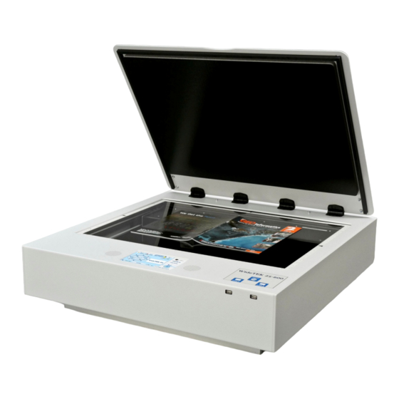
A.10 Device Overview Picture 6: WideTEK 25-600 front view The main components of the WideTEK 25-600 are: Internal loudspeakers On/off button and status LEDs of the USB connectors. Two USB connectors for storage mediums. Touchscreen A.10.1 Connectors on the Back... -
Page 26: Connecting To The Power Source
After the power source is connected and the main power switch is turned on, the symbol in the on/off button lights up. Red illumination of the on/off button signals that the WideTEK 25-600 is in standby mode. Page 26 Manual... -
Page 27: Powering Up The Widetek 25-600
To turn off the WideTEK 25-600 press and hold the on/off button for at least three seconds. While pressing the button, a “click” sound is audible. The content of the touchscreen and the TFT flat screen (if connected) changes and display the message: Going to shut down now …... -
Page 28: B Touchscreen Operation
Depending on the selected mode, the menus displayed on the screen can vary. GENERAL NOTICE This manual describes the functions of a complete equipped WideTEK 25-600 scanner. If your device is not equipped with all features, deviations are possible. Select Application Screen... -
Page 29: B.2 Start Screen Of The Kiosk User Interface
Start Screen of the Kiosk User Interface After touching the Scan2Net button the Viewer&Job Control screen is displayed on the touchscreen. Picture 9: Viewer&Job Control screen The touchscreen is structured in four sections, which allow operators to control and select various functions of the scanner. -
Page 30: B.2.1 Control Fields Of The Touchscreen
B.2.1 Control Fields of the Touchscreen By touching the buttons in section 2 each menu screen can be reached directly. The chapters B.3 to B.6 describe the functions of the menus in detail. Touch this button to start the scan sequence. Touch this button to return to the start screen from every other menu. -
Page 31: Picture 10: Document Source Screen, Part 1
Touchscreen – Document Source The Document Source screen allows selecting from a wide range of scan parameters. Picture 10: Document Source screen, part 1 The number of menu items and the content of the menus can vary. This depends on the selected setup. The setup can be changed by the administrator in the Poweruser menu. -
Page 32: B.3.1 Format
B.3.1 Format The Format button allows selecting the scan area size. Depending on the Document Mode selected, the available formats will vary. The bottom line of the button Format shows the current format setting. Picture 12: Selector for Format settings The following subchapters describe the available combinations of document mode and format. -
Page 33: B.3.1.2 Auto
B.3.1.2 Auto The complete scan area will be scanned. Picture 14: Format mode Auto The resulting image will be reduced to the document size. If the document is not exactly aligned horizontally, the resulting images will have the smallest possible black margin. The black margin depends on the size of rectangle which covers the complete document. -
Page 34: B.3.1.4 Din
B.3.1.4 DIN Picture 16: Format mode DIN When selecting DIN, an additional small window opens. It shows the available DIN (=ISO) document sizes as well as 25 inch width as scan area dimension. All formats are positioned symmetrically to the horizontal middle of the glass plate. Some markings at the margin of the glass plate help to find the right position for the document. -
Page 35: B.3.2 Splitting Image
B.3.2 Splitting Image The button Splitting Image is used to select splitting the document scanned for the output images. Picture 18: Splitting Image Left The selected format will be scanned completely. Only the left half of the selected format will be displayed. Right The selected format will be scanned completely. -
Page 36: B.3.3 Exposure
B.3.3 Exposure The Exposure screen allows selecting the functions Black Cut and Auto. Fixed switches the function off. Picture 20: Exposure Modes When Black Cut or Auto is selected a numeric key pad opens. Picture 21: Numeric key pad to set threshold value Black Cut Sets the threshold for black. -
Page 37: B.3.4 Bidirectional Scan
B.3.4 Bidirectional Scan The WideTEK 25-600 is able to scan in unidirectional direction and in bidirectional direction. Activating the bidirectional scan will save time because over a higher document throughput. Picture 22: Selecting Bidirectional Scan The camera stops after scanning at the front side of the scanning area and does not return to the start position. -
Page 38: B.3.5 Resolution
Resolution The Resolution setting allows selecting a resolution from a list of resolution values supported by the WideTEK 25-600 scanner. Picture 23: List of Resolutions The list can be opened by touching the blue arrow symbol beside the currently selected value. -
Page 39: B.3.7 Auto Density [Binary]
B.3.7 Auto Density [Binary] This control specifies the value used to decide whether a pixel belongs to the background or to the document. Default value: 70 Picture 25: Controller for Auto Density When scanning dark documents, the value should be reduced gradually until the desired result is achieved. -
Page 40: B.3.8 Stitching
B.3.8 Stitching The Stitching selector allows selecting the Stitching method. Picture 26: List of stitching methods Fixed Select this setting when scanning plain documents. Adaptive 2D Default setting. Select this setting when scanning documents with uneven structured surface, e.g. multiple folded papers. The image data will be merged dynamically. -
Page 41: B.3.9 Color Space
B.3.9 Color Space The Color Space selector allows selecting from three pre-defined color spaces for the images. Picture 27: List of predefined color spaces Native The color space of the scanner. The Gamma value can be modified with slider in the Image Quality screen. Chapter B.4.5 gives more information. -
Page 42: Picture 28: Image Quality, Screen 1
Touchscreen – Image Quality The Image Quality screen allows setting a wide range of image quality parameters. Picture 28: Image Quality, screen 1 In color mode Binary, the menu items will be extended with Invert and Despeckle. Picture 29: Image Quality, screen 2 Page 42 Manual... -
Page 43: B.4.1 Color Mode
B.4.1 Color Mode By touching the selection arrow of the Color Mode section the list of available color modes opens. Picture 30: List of Color Modes Touch the title of the desired color mode to select the mode. The list closes subsequently. Picture 30 shows the available color modes. -
Page 44: B.4.2.2 Tiff
B.4.2.2 TIFF Picture 32: Submenu File Format TIFF With the TIFF file format, the compression method of the file can be selected with the TIFF Compression buttons. CCITT G4 Recommended with color mode Binary. JPEG Recommended for all other color modes. None Disables the data compression. -
Page 45: B.4.3 Brightness
B.4.3 Brightness Picture 34: Brightness slider Brightness slider defines the resulting brightness in the image. Lower brightness values result in darker images, higher values result in brighter images. Values close to 0% or to 100% may result in unwanted artifacts. Move the slider indicator to the desired position to set the value. -
Page 46: B.4.7 Image Rotation
B.4.7 Image Rotation Picture 38: Image Rotation The value selected from the list defines the rotation of the image in a clockwise direction. The image will be rotated directly after scanning and before display B.4.8 Mirror Picture 39: Mirror This control mirrors the image along the selected mirror axis. Using this setting can be helpful if scanning transparencies from the back. -
Page 47: Picture 43: Scanned Image In Preview Area
Touchscreen – Viewer&Job Control The Viewer Control screen allows the operator to control and modify the image on an external TFT flat screen. The external screen can be connected to the scanner at the connectors at the backside (see Picture 7, detail 6). Picture 42: Viewer&Job Control screen The preview section (1) represents the TFT flat screen. - Page 48 The controller is structured in three round elements (circles). The outer circle contains the keys to move the zoomed area across the image. The middle circle contains the keys to zoom in zoom out rotate the image in clockwise direction in steps of 90 degrees scale the image to the real size of the source document.
-
Page 49: B.5.1 Job Mode
B.5.1 Job Mode The bottom line of the Viewer&Job Control screen is different to the bottom line of the other screens. Picture 44: Bottom line with status The bottom line shows • the current scan mode status, • the button to switch the job mode between Single and Job mode •... -
Page 50: Picture 46: Disclaimer When Staring The Job Mode
When Job mode is selected, the contents of the touchscreen change. At first a disclaimer opens, which has to be accepted. Picture 46: Disclaimer when staring the Job mode After accepting the disclaimer, the Viewer&Job Control screen opens. It contains some additional control buttons above and below the preview section. Picture 47: Job mode start screen Page 50 Manual... -
Page 51: B.5.1.1 Navigating Through The List Of Images
B.5.1.1 Navigating through the list of images The control buttons allow navigation through the list of scanned images and image handling while working in Job mode. The currently scanned image is always displayed in the preview section of the touchscreen and will be added as last image to the list displayed at the TFT flat screen. Function of the control buttons: Moves up- and/or downwards through the list of images to mark an image. -
Page 52: B.5.1.2 Moving An Image To Another Position
B.5.1.2 Moving an image to another position Use the upwards / downwards buttons to mark the image to be moved. Press this button to select the image. The image now can be moved with the upwards / downwards buttons to the new position. Press this button again to place the image at the new position. -
Page 53: B.5.1.6 Finalizing The Job Mode
B.5.1.6 Finalizing the Job mode Before finalizing the Job mode the scanned images can be transferred to different destinations. Picture 49: Destination to finalize Job mode The destinations are identical to the destinations described in chapter B.6 and its subchapters. Before the Job mode will be finalized, a message is displayed at the touchscreen. -
Page 54: Picture 51: Send To Screen #1
Touchscreen – Send To This menu provides the output options in order to transfer the scanned images to the desired destination. Picture 51: Send To screen #1 Due to the dimension of the touchscreen, not all output options can be displayed at the same time. -
Page 55: B.6.1 Changing A File Name Or Other Entries
B.6.1 Changing a file name or other entries In some of the option menus the file name can be changed. To change the file name, touch the respective line. The screen changes to an alphanumeric keyboard. Picture 53: Alphanumeric keyboard Use the arrow keys to position the cursor in the line. -
Page 56: B.6.2 Usb Options
B.6.2 USB Options Two USB connectors are available at the front of the scanner to connect suitable USB data carriers, for example USB sticks. Touching USB Options displays the directory of a connected USB data carrier. Picture 54: Directory of connected USB data carrier While the directory of the USB data carrier is displayed, the LED indicator of the respective connector is continuously illuminated. -
Page 57: B.6.3 Copy Options
B.6.3 Copy Options Touch Copy Options to switch to the screen with the preset copy option configurations. Three preset options can be stored and activated with the buttons Copy1 to Copy3. Picture 55: Parameters of Copy Options The parameters displayed in the above picture can only be changed from the Scan2Net user interface. -
Page 58: B.6.4 Ftp Options
B.6.4 FTP Options Touch FTP Options to switch to the screen with the preset FTP server configurations. Three preset FTP servers can be stored and activated with the buttons FTP 1 to FTP 3. Picture 57: Parameters of FTP Options From the touchscreen, only the entry for File Name can be changed. -
Page 59: B.6.5 Network Options
B.6.5 Network Options Touch Network Options to switch to the screen showing the preset network configurations. Three preset configurations can be stored and activated with the buttons Network 1 to Network 3. Picture 58: Parameters of Network Options From the touchscreen, only the entry for File Name can be changed. To change the entry, touch the respective line. -
Page 60: B.6.6 Mail Options
B.6.6 Mail Options Touch Mail Options to switch to the screen showing the preset email configurations. Three preset configurations can be stored and activated with the buttons Mail 1 to Mail 3. Picture 59: Parameters of Mail Options To change an entry, touch the respective line. From the touchscreen the values for •... -
Page 61: B.6.6.1 Transaction Modes
B.6.6.1 Transaction modes Two transaction modes are available for the mail transfer. See chapter C.3.7.1, section Transaction mode, for detailed information. The mode, selected in the Scan2Net user interface, influences the process when a scanned image should be mailed. Automatic When pressing the button Mail image via SMTP at the touchscreen, the image will be sent to the address defined in the screen Mail Options (Picture 59). -
Page 62: C Software Operation
Software Operation Essentially, the scanner is a web server and comes with its own HTML-based user interface. To access a Scan2Net scanner, any standard web browser can be utilized. A basic requirement before using the integrated user interface is to configure the browser as follows: •... -
Page 63: C.2 The Main Screen
The Main Screen After launching the scan application, the main screen of the integrated user interface will open. The main screen is structured in three parts. Switching between the sections is done with a mouse click. Picture 62: Main screen 1: The menu bar of the large frame on the upper right part has five menu items: ... -
Page 64: Picture 63: Shutdown Confirmation
2: The control buttons in the lower part of the screen control the output modes. When selecting Save the scanned image will not be displayed. Instead of the second window a box opens where the desired directory can be set. As default the output mode Show is selected. -
Page 65: C.2.1 The Options Screen
C.2.1 The Options Screen Options Picture 64: screen Document Mode Defines the document type to be scanned. Currently only Flat Mode is available. In this mode the scanner works with a fixed focus setting, regardless of the actual shape of the document. Preview Scale Allows setting the preview relation. - Page 66 Bidirectional Scan Yes The camera scans the selected scan area size and stops at the position where the scan area ends. The next scan sequence starts from this position in opposite direction. The camera scans the selected scan area size and returns to its initial start position.
-
Page 67: C.2.2 The Properties Screen
C.2.2 The Properties Screen Properties Picture 65: screen Color Mode This mode allows selecting from various color modes. The available color modes are displayed in the picture on the left. To select a color mode first click on the selection arrow, then select a mode from the list. -
Page 68: Picture 66: 24Bit Color, File Format Tiff
File Format Defines the file format that is used to store a scanned document. Note Interdependencies exist between Color Mode File Format. That means, it is not possible to combine all color modes with all file formats. For example, an image scanned in “24bit Color” cannot be stored in TIFF file format with TIGG G4 compression. - Page 69 Splitting Image This function allows splitting the image of the scanned document. No page splitting. Auto The first image is taken from the side which is defined in the setup menu as start page. Click on Preview or Scan now again to get the other half.
-
Page 70: Picture 67: Maximum Deskew Angle
Orientation Only available with the ISO formats, the ANSI formats and the format “Maximum”. Landscape Scans the selected format in landscape orientation. The scaling of the glass plate helps to position the document correctly. Portrait Scans the selected format in portrait orientation. The scaling of the glass plate helps to position the document correctly. -
Page 71: C.2.3 The Camera Screen
C.2.3 The Camera Screen Camera Picture 68: screen Resolution [DPI] This field allows setting the desired resolution in two ways. Selecting the resolution: Click the selection arrow beside the right field. Select the desired value from the list. Entering the resolution: Enter any value between 150 dpi and 1200 dpi into the left field. -
Page 72: Picture 69: Exposure Control Slider
Exposure Exposure function sets the threshold value for the black cut function or for the auto exposure function. Picture 69: Exposure control slider When Black Cut or Auto is selected, an additional slider is displayed. This slider allows setting the threshold – defined in percent – for the Black Cut function and the Auto function. - Page 73 Color Space Color Space selector lists three settings for the color space used by the scanner when displaying the scanned images. AdobeRGB Shows the scanned images with the predefined Gamma setting of the AdobeRGB color space. sRGB Shows the scanned images with the predefined Gamma setting of the sRGB color space.
-
Page 74: C.2.3.1 Threshold Dynamic / Threshold Fixed
C.2.3.1 Threshold Dynamic / Threshold Fixed Picture 70: Threshold method selector Only with color mode Binary. Allows selecting between Dynamic Fixed threshold. Dynamic The contrast level in the image varies depending on the content of the document. This can help to improve fine details in the image. Note: In Dynamic mode set the contrast slider carefully because if set to the extremes, unexpected image artifacts can occur. -
Page 75: C.2.4 The Settings Screen
C.2.4 The Settings Screen Settings Picture 72: screen Language Selector Sets the language of the user interface. Available languages are: Czech (čeština) German (deutsch) English (english) Spanish (español) French (français) Polish (polski) Portuguese (português) Russian (русский Cyrillic script) Turkish (türkçe) Chinese (Chinese symbols) Note: After selecting the language the user interface changes immediately to the... -
Page 76: Picture 73: Available Skins
Skin Selector This selector allows the operator to choose between different surfaces (skins) for the user interface. The skins differ in color and in the graphic elements used for the buttons and controls. The cutout on the left shows the currently available skins. Additional skins can be designed and integrated by the user. -
Page 77: C.2.5 The Format Screen
C.2.5 The Format Screen Format Picture 75: screen When selecting the Format screen, a test image is displayed. If a scan has been executed before selecting the Format screen, the image scanned and displayed at last is displayed. The dimension of the image depends on the selected format in the Properties screen. -
Page 78: Picture 76: Rectangle Dragged With Mouse
To select a specific area of the image, click with the mouse in the preview area and drag a rectangle. Dragging the rectangle with the mouse starts in the upper left corner and ends in the lower right corner. Click the Zoom in button to display the selected area of the image in detail. ... -
Page 79: Manual Page
Select output option here Picture 78: Output options Ten output options are available on a WideTEK 25-600 scanner. Each option is selectable at the bottom part of the main window. The output mode will be saved when the scanner is turned off. It is pre-selected when the scanner will be stared again. -
Page 80: C.3.1 Output Option Save
C.3.1 Output Option Save Picture 79: Output Option Save Select the output mode by clicking with the mouse on the button Save. When the output option Save is selected a preview window will not open. This output option scans to a local or network disk drive. After the scan is performed, a window opens where the default file name is shown. -
Page 81: C.3.2 Output Option Show
C.3.2 Output Option Show In most cases, the button Show is activated. Picture 81: Output Option Show After scanning, an additional window opens and shows the image. The headline of the additional window contains identical buttons as the main window, except the items Show and Print. -
Page 82: C.3.3 Output Option Multipage
C.3.3 Output Option Multipage Picture 83: Output Option Multipage Selecting the output option Multipage allows saving scanned images in a so called “Container” format. The available “Container” format depends on the file format of the image (see chapter C.2.2). Note: Multipage is selected, a preview window will not open. - Page 83 While the scan sequence is running, a status window shows the current status. At the end of the scan sequence the window closes. To view the scanned images and to select the images, click on the link Finalize below the Multipage button.
-
Page 84: C.3.4 Output Option Print
C.3.4 Output Option Print This output option prints the image at a locally configured printer. Picture 85: Output Option Print After the scan is executed, the standard printer interface opens. The user can select one of the available printers. Picture 86: Available List of Printers for Option Print Page 84 Manual... -
Page 85: C.3.5 Output Option Copy
C.3.5 Output Option Copy This output option prints directly to a previously installed network printer. The Option is used to configure the remotely connected printer. Picture 87: Output Option Copy C.3.5.1 Remote Printer Parameter Description Printer Preset Choose a printer configuration out of five possible sets of parameters. - Page 86 Remote Printer, continued Parameter Description Network Type Select Homegroup Network or Workgroup Network. (with SMB Printer Queue only) Password Enter the password for the Homegroup Network. (with SMB Printer Queue Homegroup Network only) Select Yes or No. Server Authentication (with SMB Printer Queue ...
-
Page 87: C.3.5.2 Printing Enhancement
Remote Printer, continued Parameter Description Duplex Print Switch on/off printing on both sides of a sheet (duplex). (not with HP Design Jet) Duplex Mode Select between Book and Notepad. Book = Binding at the wide side of the paper sheet. Notepad = Binding at the narrow side of the paper sheet. -
Page 88: C.3.5.3 Accounting
C.3.5.3 Accounting Only available with Konica Minolta Bizhub Series Parameter Description Accounting Yes / No Account Name Enter the account name here. Use Password Yes / No Account Password Enter the password for the accounting here. Hold Job Yes / No Job Type Public / Private Hold Key... -
Page 89: C.3.5.4 Extended Print Parameters With Ipf Option Installed
C.3.5.4 Extended print parameters with iPF option installed After activating the option for Canon iPF printer the number of printing parameters will be extended. The following additional parameters are available. Parameter Description Data Format After installing the option the list of data formats is extended by Canon iPF Series Changing the data format will also change the options. -
Page 90: C.3.5.5 Printing Enhancements With Ipf Option Installed
C.3.5.5 Printing Enhancements with iPF option installed After activating the option for Canon iPF printer the number of printing enhancements will be extended. The following additional parameters are available. Parameter Description Quality Optimized Level Image: Optimized for color printouts. Linedrawing: Optimized for bitonal line drawings. Quality Level Toggle the printing quality from draft to high quality. -
Page 91: C.3.6 Output Option Ftp
C.3.6 Output Option FTP The scanner can directly scan to an FTP server. Picture 88: Output Option FTP Upload Go to Options to configure the FTP interface. A configuration window will pop up. C.3.6.1 FTP Server Parameter Description Preset Choose a preconfigured set of parameters out of five possible sets of parameters. - Page 92 FTP Server, continued Parameter Description Address Enter the IP address of the remote FTP server. Port (21) Enter the IP port of the remote FTP server. Default is port 21. Server Authentication Select Anonymous FTP or Login/Password. Login Enter the login name. (if Login/Password is selected) Password Enter the password for the login at the remote FTP server.
-
Page 93: C.3.7 Output Option Mail
C.3.7 Output Option Mail The scanner can directly send each scan via e-mail. Picture 89: Output Option Mail Go to Options to configure the mail interface. The above configuration window will pop C.3.7.1 Mail Server Parameter Description Preset Choose a preset out of five possible sets of parameters. If you click on Change Name you can change the name of this... - Page 94 Mail Server, continued Parameter Description Address Enter the IP address of the outgoing mail (SMTP/LMTP) server. Port (25) Enter the IP Port of the outgoing mail server. Default: Port 25. Server Authentication Set to YES if the mail server requires an authentication. Login Enter the user name for authentication at the outgoing mail server.
-
Page 95: C.3.7.2 Transaction Mode Interactive
C.3.7.2 Transaction mode interactive If Transaction mode interactive is selected, an additional window opens after scanning. Picture 90: Parameters for transaction mode “interactive” Here all parameters can be entered for the mail transfer. Click into the respective field and enter the desired parameters. Each recipient address will be stored when the Apply button is pressed. -
Page 96: C.3.7.4 Configuring The Ldap Directory Service
C.3.7.4 Configuring the LDAP Directory Service Picture 92: LDAP Directory Service parameters Parameter Description LDAP Server Enter here the IP address of the LDAP server. Port (389) Enter the IP Port which is used for the connection. Default: Port 389. Protocol Version LDAP Version 2 / LDAP Version 3 Server Authentication... -
Page 97: C.3.8 Output Option Network
C.3.8 Output Option Network SMB is a network protocol which is used by Microsoft Windows-based networks. If output option Network is selected, the scans will be stored directly in a network directory. Picture 93: Output Option Network Go to Option to configure the SMB Upload interface. -
Page 98: C.3.8.1 Smb Configuration
C.3.8.1 SMB Configuration Parameter Description Preset Choose a preset out of five possible sets of parameters. If you click on Change Name you can change the name of this set. Port (139) Enter the IP port of the SMB network communication. Default is port 139. -
Page 99: C.3.9 Output Option Web
C.3.9 Output Option Web This option allows the user to store its files and images in the so called “Cloud”; a web space, which is offered by providers at their servers. Three different kinds of web services are available from the scanner. Picture 94: Output Option Web Go to Option... -
Page 100: C.3.9.1 Web Service Configuration
C.3.9.1 Web Service Configuration Parameter Description Preset Choose a preconfigured set of parameters out of five possible sets of parameters. If you click on Change Name you can change the name of this set. Use a Proxy? Switch on/off the use of a proxy for connecting to a remote server outside the local network. - Page 101 Parameter Description Collection Enter the name of the directory where the files should be stored. (only with WebDAV) Upload Mode Select the data format. Currently the file size for the data format “Document” and “File” is limited to 1 MB. (only with Google Docs) If Document is selected, a new document will be opened and the image will be imported into the document.
-
Page 102: C.3.10 Output Option Usb
C.3.10 Output Option USB Universal Serial Bus (USB) is a serial bus standard for interface devices, e.g. storage devices. The output option USB enables direct scanning to a USB Standard-A flash memory data storage device. Picture 95: Output Option: USB There are two USB connectors at the front panel of the scanner. -
Page 103: C.3.10.1 Usb Storage Device
C.3.10.1 USB Storage Device Go to Options to configure the USB interface. A configuration window will pop up. Parameter Description Partition Shows the status and available memory of the currently mounted partition of the connected USB flash device. Directory Allows choosing a subdirectory on the connected USB drive for storing the scans. -
Page 104: C.4 Information
Information The start screen (Picture 61) shows three buttons. The button Information gives a short summary of the device parameters. Picture 97: Information The screen is helpful if technical support is necessary. It shows e.g. the exact device type, the installed firmware version as well as currently installed options. Click the button Back to return to the start screen. -
Page 105: C.5 The Setup Screen
The Setup Screen The system level is divided in three access levels. The access levels Poweruser and Admin are protected through a password. The User access level allows showing certain information about the system like power up time, remaining lamp life time or firmware version. Furthermore the access level User allows setting some basic parameters. -
Page 106: C.5.2 Access Level User
C.5.2 Access Level User Click the button User . This will open the below displayed screen. Picture 99: User screen The user screen is divided into two sections. The section Device Information shows some details of the scanner and gives a general operation information. -
Page 107: C.5.2.1 Device Info Screen
100) will be displayed. Specific information can be reached by clicking the links below the headline Device Info. Picture 100: Device Info screen The tables following the keyword show the current status of the WideTEK 25-600 scanner. Manual Page 107... -
Page 108: Picture 101: Firmware Information
The most important information for users is the firmware version in the second table. Picture 101: Firmware information Other information may be of interest if a service technician is onsite or if the service hotline is called. To return to the USER screen (Picture 99) scroll down completely and click the Back to Main Menu button. -
Page 109: C.5.2.2 Operation Info Screen
C.5.2.2 Operation Info Screen In the section Information click the button Operation Info and the following list will show various scan counters and elapsed times. Picture 102: Operation Info screen The following table gives a brief description. Field Description Total Scan Count The total number of scans performed since the scanner left the factory. -
Page 110: C.5.2.3 User Settings Screen
C.5.2.3 User Settings Screen In the section User Settings click the button User Settings and the following screen will be displayed. Picture 103: User Settings start screen Power Saving screen will be displayed as start screen of the User Settings section. -
Page 111: C.5.2.3.1 Language Selector
Use the function Language Selector to set the language for the Scan2Net user interface of the WideTEK 25-600 scanner. Picture 104: Language Selector screen Click on the selection arrow and a list of available languages opens. Select the desired language for the user interface with a mouse click. -
Page 112: C.5.2.3.2 Power Saving
C.5.2.3.2 Power Saving Use the function Power Saving to set the time until the scanner goes into stand-by mode. Click on the link Power Saving. Click on the selection arrow and select the desired value from the list. Picture 105: User Settings screen The Energy Star guidelines define the default time until the device goes into stand-by to be 15 minutes. -
Page 113: C.5.2.3.3 Volume
C.5.2.3.3 Volume Click the button Volume to set the loudspeakers volume of the scanner. Picture 106: Volume level A screen opens and shows a graphic to symbolize the volume. Click on the percentage value to change the volume level. The color of the graphic will change depending on the selected volume level. -
Page 114: C.5.2.3.4 Foot Pedal
C.5.2.3.4 Foot Pedal Click the button Foot Pedal to define a function for the foot pedals. Picture 107: Foot pedal settings The scanner has one connector (FS1) on its back to connect a foot pedal. For the foot pedal a specific action can be defined. Click below the designated foot pedal and select from the drop-down list which action should be executed when the pedal is operated. -
Page 115: C.5.2.3.5 Splitting Start Page
C.5.2.3.5 Splitting Start Page Click the button Splitting Start Page and select either the left page or the right page as start page. Picture 108: Splitting start page In some cases it is necessary to start splitting the documents image in reverse order, i.e. starting with the right side followed by the left side in the second step. -
Page 116: D Tests And Troubleshooting
Tests and Troubleshooting Troubleshooting Matrix Fields with a light blue background need the Poweruser access level. All other fields are available to all users. Problem Possible cause Action The touch panel does not No power Check main outlet, power cord, and show the stand-by message. -
Page 117: D.2 Error Codes
Error Codes The scanner does report error conditions on the display and through the API. Some errors are only sent to the API. A green problem description signals that operation of the scanner is still possible although the error will have an influence on the behavior or quality of the scanner. A red problem description signals that a problem occurred which will stop the scanner and further scanning is inhibited. - Page 118 Error codes, part 2 Error # Error message shown in Error message sent to Problem description the display application File format not supported. The specified file format is not supported or it is invalid in combination with the color mode. Preview not possible The application specified an invalid preview scale.
-
Page 119: D.3 Warnings
Error codes, part 3 Error # Error message shown in Error message sent to Problem description the display application Error 69: Camera 1 adc error. Test data transfer through analog ADC error camera 1 digital converter failed. Check cables / connectors to camera 1. Error 70: Camera 2 adc error. -
Page 120: E Technical Data
Technical Data Scanner Specifications Optical System Maximum document width 25 x 18.5 inches / 635 x 470 mm Optical / interpolated resolution 1200 x 600 dpi / 1200 x 1200 dpi Camera type Two tricolor CCDs, encapsulated and dust- proof Color depth 12 bit grayscale (internal resolution) 36 bit color (internal resolution) -
Page 121: E.3 Electrical Specifications
Electrical Specifications External Power Supply Voltage 100 – 240 V AC Frequency 47 – 63 Hz Inrush current 120 A max / 264 V AC Efficiency 87 % Operating temperature 0 to 65 °C / 32 to 149 °F Operating humidity 10 to 93 % RH, non-condensing ECO standard CEC level V... -
Page 122: E.5 Ce Declaration Of Conformity
Image Access GmbH Hatzfelder Strasse 161 – 163 42281 Wuppertal, Germany herewith declares that the Product: WideTEK 25-600 Scanner Model Designation: WT25 –XXX XXX represents the device version number and configuration details) Serial number: is in conformity with the following European standards and IEC directives:... - Page 123 EMC: Directive 2004/108/EEC Class A: EN 55022:2010 EN 61000-3-2:2006 + A1:2009 + A2:2009 EN 61000-3-3:2008 EN 55024:2010 EN 61000-4-2:2009 EN 61000-4-3:2006 + A1:2008 + A2:2010 EN 61000-4-4:2004 + A1:2010 EN 61000-4-5:2006 EN 61000-4-6:2009 EN 61000-4-11:2004 Wuppertal, April 2012 Thomas Ingendoh , President and CEO Manual Page 123...
-
Page 124: E.6 Fcc Declaration Of Conformity
FCC Declaration of Conformity Responsible party: Image Access GmbH Hatzfelderstrasse 161 – 163 42281 Wuppertal, Germany Product: WideTEK 25-600 Model Designation: WT25 –XXX XXX represents the device version number and configuration details) Serial number: This device complies with FCC 47, Part 15, Class A and ICES-003, Class A. - Page 125 For your notes Manual Page 125...
Need help?
Do you have a question about the WideTEK 25-600 and is the answer not in the manual?
Questions and answers