Image Access WideTEK 12 Setup Instructions
Hide thumbs
Also See for WideTEK 12:
- Operation manual (99 pages) ,
- Setup instructions (72 pages) ,
- Setup manual (44 pages)
Table of Contents
Advertisement
Quick Links
Advertisement
Table of Contents

Related Manuals for Image Access WideTEK 12


Summary of Contents for Image Access WideTEK 12
- Page 1 WideTEK® 12 WideTEK® 25 Setup Instructions English 07/2019...
-
Page 2: Table Of Contents
Contents Revision History ..................5 Information about the Instructions and the Manufacturer ....... 6 Keep Instructions with the Scanner ............6 Design Features in Text ................7 Design Features in Pictures..............8 Associated Documents ................8 Copyright ....................8 Contact Data of the Manufacturer in Germany ........9 Technical Support .................. - Page 3 Device Location ..................22 Environment ..................22 Prepare for Setup ..................23 Remove the Transport Locks ..............23 Connect the Power Supply ..............24 Establish the Network Connection ............25 Connect the Optional Foot Switch ............25 Connect the Optional Monitor .............. 26 Connect the Optional Touchscreen ............
- Page 4 Surfaces ....................86 Cleaning the Glass Plate................. 87 Repair ..................... 87 Technical Specifications ................88 WideTEK® 12 Scanner Specifications ............. 88 WideTEK® 25 Scanner Specifications ............. 90 Ambient Conditions ................91 Electrical Specifications ................. 91 Dimensions and Weight WideTEK® 12 ..........93 Dimensions and Weight WideTEK®...
-
Page 5: Revision History
Revision History Revision History Date Rev. Name Description of Reason of Change Change 16.10.2017 First draft First published version 23.07.2019 Second draft New power button, optional backlight... -
Page 6: Information About The Instructions And The Manufacturer
Information about the Instructions and the Manufacturer Information about the Instructions and the Manufacturer These instructions show you how to safely prepare and perform the setup for the flatbed scanners WideTEK® 12 and WideTEK® 25. The flatbed scanners WideTEK® 12 and WideTEK® 25 are hereinafter referred to as "Scanner". -
Page 7: Design Features In Text
Information about the Instructions and the Manufacturer Design Features in Text Many text passages in these instructions have been formatted to indicate specific elements, as illustrated below: Normal text BUTTONS OF THE SCREEN PAGE "Menu names" ➢ Action steps • Enumeration of the first level Cross-references Tips contain additional information, such as special information to prepare for and perform the setup. -
Page 8: Design Features In Pictures
These instructions contains information that is subject to copyright. These instructions may not be reproduced in any form, printed, filmed, edited, copied or distributed, in whole or in part, without prior written permission from Image Access GmbH. © Image Access GmbH 2019 All rights reserved. -
Page 9: Contact Data Of The Manufacturer In Germany
Information about the Instructions and the Manufacturer Trademarks Scan2Net®, Scan2PAD®, Bookeye® and WideTEK® are registered trademarks of Image Access, all other trademarks are the property of their respective owners. Contact Data of the Manufacturer in Germany Image Access GmbH Hatzfelderstraße 161-163... -
Page 10: Safety
In this case, replace the power supply with a power supply of the same type. ➢ Do not use the scanner if it is visibly damaged. In this case, unplug the power cord from the wall outlet. Contact Image Access technical support, see section Technical Support starting at page 9. - Page 11 Safety Avoid Burns ➢ Do not cover the existing openings in the scanner housing. They serve to ventilate. Covering the openings could cause overheating. ➢ Do not place the scanner in front of air conditioning units, which produce high heat. Avoid Cuts The glass plate on the scanner is only suitable for the weight of documents.
-
Page 12: Avoiding Property Damage And Malfunctions
Safety Avoiding Property Damage and Malfunctions ➢ Ensure adequate ventilation to comply with the environmental conditions. ➢ Prior to initial installation, remove the mounted transport locks. ➢ Install the transport locks before transporting the scanner to a new location. ➢ Do not place the scanner in the vicinity of devices that emit strong electromagnetic radiation. -
Page 13: Design Features Of Warning Notices
Safety Design Features of Warning Notices In these instructions, the following warning information can be found: WARNING Notices with the word WARNING warn about a dangerous situation that could lead to death or serious injuries. CAUTION Notices with the word CAUTION warn about a situation that could lead to light or medium-scale injuries. -
Page 14: Description
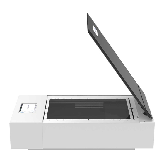
Description Description Purpose and Function The scanner is used for scanning images and documents. It is designed for use in enclosed spaces in the commercial sector. WideTEK® 12/25 Overview Name Cover Glass plate Power button USB connector Touchscreen... -
Page 15: Widetek® 12/25 Overview With Backlight (Optional)
Description WideTEK® 12/25 Overview with Backlight (Optional) Name Backlight Glass plate Power button USB connector Touchscreen... -
Page 16: Rear View Of The Widetek® 12
Description Rear View of the WideTEK® 12 Name Main switch Network connector 24 Vdc connector for external power supply Foot switch connector Recovery key connector HDMI connector USB connector... -
Page 17: Rear View Of The Widetek® 25
Description Rear View of the WideTEK® 25 Name Main switch Network connector 24 Vdc connector for external power supply Foot switch connector HDMI connector USB connector Recovery key connector... -
Page 18: User Interfaces
Description User Interfaces The scanner can be operated in four ways. • Via the integrated small touch screen and the ScanWizard App user interface. • Via the externally connected former preview monitor, as touch screen for the ScanWizard Touch user interface. •... -
Page 19: Setup Menu Overview Screen
Description Setup Menu Overview Screen Name Buttons and parameters Menu name Display the online help Button to leave the setup menu to the start screen Firmware version IP address Serial number The display of the online help is only available when a second touchscreen is connected to the scanner. -
Page 20: Rating Plate
Description Rating Plate The rating plate is attached to the back of the scanner. The following figure shows the WideTEK® 12 rating plate. - Page 21 Description The following figure shows the WideTEK® 25 rating plate.
-
Page 22: Device Location
Device Location Device Location Environment Choose a location that complies with the temperature and humidity specifications. Please allow • a minimum distance of 150 mm (6 inches) from any side walls, • a minimum distance of 300 mm (12 inches) from a back wall, •... -
Page 23: Prepare For Setup
Prepare for Setup Prepare for Setup Remove the Transport Locks The scanner is equipped with two transport locks. Transport locks are located on the bottom left and right. They can be identified by the plastic tab (1). The following figure shows the WideTEK® 12 model. You must remove the transport locks before using the scanner for the first time. -
Page 24: Connect The Power Supply
Prepare for Setup Connect the Power Supply WARNING Risk of electric shock due to incorrect connection. ➢ Ensure that the power receptacle intended for the connection is properly grounded. ➢ Ensure that the power receptacle intended for the connection of the scanner is properly fused. CAUTION Incorrect laying of the connection cables can cause tripping. -
Page 25: Establish The Network Connection
Prepare for Setup Establish the Network Connection CAUTION Incorrect laying of the connection cables can cause tripping. Fractures, contusions and bruises can be the result. ➢ Place the connecting cables so that no one can trip over them. To establish the network connection, proceed as follows: ➢... -
Page 26: Connect The Optional Monitor
Prepare for Setup Connect the Optional Monitor CAUTION Incorrect laying of the connection cables can cause tripping. Fractures, contusions and bruises can be the result. ➢ Place the connecting cables so that no one can trip over them. To connect the optional monitor, proceed as follows: ➢... -
Page 27: Switch On The Scanner
Prepare for Setup Switch On the Scanner ATTENTION! Damage to the scanner can be caused by a transport lock not removed prior to power on. ➢ Ensure that both transport locks are completely removed from the scanner. To switch on the scanner, proceed as follows: ➢... - Page 28 Prepare for Setup To start the scanner from standby mode, proceed as follows: ➢ Touch the power button (2). The power button lights up in blue. The scanner performs a system test. After a short wait, the "Start screen" is displayed in English.
-
Page 29: Switch Off The Scanner
Prepare for Setup Switch Off the Scanner To switch the scanner to standby mode after performing the setup, proceed as follows: ➢ On the "Start screen" screen tap on SHUTDOWN (1). ➢ Confirm with YES. The scanner shuts down. This process can take up to 40 seconds. The scanner is in standby mode. - Page 30 Prepare for Setup To switch off the scanner using a hard shutdown, proceed as follows: ➢ Press and hold the power button for longer than four seconds. The power supply to the scanner is immediately interrupted. ➢ Press the MAIN SWITCH (1) in the "0" position.
-
Page 31: Perform Setup
Perform Setup Perform Setup Change the Menu Language To change the menu language, proceed as follows: ➢ Tap the LANGUAGE (1) button to see all available languages. - Page 32 Perform Setup A window for selecting the language appears. ➢ To display more languages, slide the scroll bar (1) downward. ➢ Tap the desired language. The window for selecting the language is closed. The "Start screen" is displayed.
-
Page 33: Activate The Setup Menu
Perform Setup Activate the Setup Menu To activate the setup menu, you must log in on the scanner. Proceed as follows: ➢ Tap the GEAR SYMBOL (1). - Page 34 Perform Setup The login window appears. ➢ In the login window, enter the login credentials. ➢ Tap on the "Username" input field. The screen keyboard is displayed. ➢ Enter the word "Poweruser". ➢ Tap on the "Password" input field. ➢ Enter the word "Poweruser". ➢...
- Page 35 Perform Setup ➢ To complete the log in, press OK (1).
- Page 36 Perform Setup The "Setup Menu" screen is displayed. White Balance: Display the "White balance" submenu Test Suite: Display the "Test Suite" submenu IP Address: Display the "IP Address" submenu User Settings: Display the "User Settings" submenu Time and Date: Display the "Time and Date" submenu Touchscreen Test: Display the "Touchscreen Test"...
-
Page 37: Perform White Balance
Perform Setup Perform White Balance ➢ On the "Setup Menu" screen, tap on WHITE BALANCE (1). - Page 38 Perform Setup The "White Balance" screen is displayed. Calibrate: Start white balance Backlight: Start white balance for backlight Delete White Delete existing white balance data Balance Data: The white balance is used to ensure the quality of the scan results. The white balance will be carried out using a test target.
- Page 39 Perform Setup ATTENTION! Impairment of the scan quality can occur if an improper test target for the white balance is used. ➢ Make sure that the test target is free from wrinkles, discolorations, cracks or other damage. ➢ Store the test target for the white balance in a safe place protected from daylight.
- Page 40 Perform Setup ➢ Close the cover of the scanner. ➢ Tap on CALIBRATE (1).
- Page 41 Perform Setup ➢ Tap on NEXT STEP (1). The following figure shows the model WideTEK® 25.
- Page 42 Perform Setup The white balance starts and the calibration is performed. During the white balance, a rotating icon appears. The entire white balance sequence takes about 40 seconds. Then, the white balance result is displayed as shown on the example below.
- Page 43 Perform Setup ➢ To perform the white balance again, tap NEW VALUES (2). ➢ To return to the previous submenu, tap BACK (1). ➢ To return to the "Start screen", tap EXIT (3).
- Page 44 Perform Setup ➢ To delete the stored data of the white balance calibration, tap DELETE WHITE BALANCE DATA (2). ➢ After deleting the stored data, run the white balance again, as described. ➢ If problems arise during the white balance calibration, contact Image Access technical support, see section Technical Support starting at page ➢...
-
Page 45: Perform White Balance With Backlight Cover
Perform Setup Perform White Balance with Backlight Cover ➢ On the "Setup Menu" screen, tap on WHITE BALANCE (1). - Page 46 Perform Setup The "White Balance" screen is displayed. Calibrate: Start white balance Backlight: Start white balance for backlight Delete White Delete existing white balance data Balance Data: The white balance is used to ensure the quality of the scan results. To perform the white balance, proceed as follows: ➢...
- Page 47 Perform Setup The following figure shows the models WideTEK® 12 and WideTEK® 25.
- Page 48 Perform Setup ➢ Tap on BACKLIGHT (1). The following figure shows the model WideTEK® 25.
- Page 49 Perform Setup ➢ Tap on NEXT STEP (1).
- Page 50 Perform Setup The white balance starts and the calibration is performed. During the white balance, a rotating icon appears. The entire white balance sequence takes about 40 seconds. Then, the white balance result is displayed as shown on the example below.
- Page 51 Perform Setup ➢ To perform the white balance again, tap NEW VALUES (2). ➢ To return to the previous submenu, tap BACK (1). ➢ To return to the "Start screen", tap EXIT (3).
- Page 52 Perform Setup ➢ To delete the stored data of the white balance calibration, tap DELETE WHITE BALANCE DATA (2). ➢ After deleting the stored data, run the white balance again, as described. ➢ If problems arise during the white balance calibration, contact Image Access technical support, see section Technical Support starting at page ➢...
-
Page 53: Assign The Ip Address
Perform Setup Assign the IP Address Manually Assign the IP Address To manually assign the IP address, proceed as follows: ➢ On the "Setup Menu" screen, tap on IP Address (1). - Page 54 Perform Setup The "IP Address" screen is displayed. Set network Accept the network settings provided settings: Reset to Factory: Reset to factory settings IP Address: Input field for the IP address Default Gateway: Input field for the gateway address Subnet Mask: Input field for data on the subnet mask IP Configuration Assign an IP address manually or automatically...
- Page 55 Perform Setup ➢ Tap the "IP Address" (1) field.
- Page 56 Perform Setup The "IP Address" window is displayed. ➢ Enter the IP address (1).
- Page 57 Perform Setup ➢ To delete a digit, move the cursor to the right, behind the digit to be deleted and tap DEL (1).
- Page 58 Perform Setup The arrow keys left (1) and right (2) next to the number "0" move the cursor within the chosen row. ➢ To complete the entry, press OK (3). ➢ Perform the settings for gateway and subnet mask in the same way.
- Page 59 Perform Setup ➢ To save the network settings, tap SET NETWORK SETTINGS (2). ➢ To return to the previous submenu, tap BACK (1). ➢ To return to the "Start screen", tap EXIT (3).
- Page 60 Perform Setup Automatically Assign the IP Address To automatically assign the IP address, proceed as follows: ➢ In the selection menu "IP Configuration Method", select the "DHCP" (3) entry. ➢ To return to the previous submenu, tap BACK (1). ➢ To return to the "Start screen", tap EXIT (2).
-
Page 61: Modify User Settings
Perform Setup Modify User Settings ➢ On the "Setup Menu" screen, tap on USER SETTINGS (1). - Page 62 Perform Setup The "User Settings" screen is displayed. Configure GUI Open the submenu for setting the application in Selection: the start screen Default: The scanner will be reset to the default settings Language: Select language Display standby Define the period of inactivity, until an optional after: external monitor and the touchscreen switch to the standby mode...
- Page 63 Perform Setup Select Language To select the language, proceed as follows: ➢ Tap the on the selection arrow of the selection menu "Language" to display the list of languages. ➢ Tap the desired language (2). ➢ To return to the previous submenu, tap BACK (1). ➢...
- Page 64 Perform Setup Set Standby Times To set the standby times, proceed as follows: ➢ Tap the selection arrow of the selection menu. ➢ Tap on the desired entry (2). ➢ Perform the settings for the screen saver and the device standby in the same way.
- Page 65 Perform Setup Configuring the GUI Selection ➢ Tap the "User Settings" screen on CONFIGURE GUI SELECTION (1).
- Page 66 Perform Setup The "Configure GUI Selection" screen is displayed. This menu displays the "EasyScan" and "ScanWizard" applications, which are available as a standard selection. If, after system start you want to display only one of the applications, proceed as follows: ➢...
- Page 67 Perform Setup By default, single mode is defined (activate the checkbox "Single mode enabled"). ➢ To start the application in job mode, uncheck the checkbox "Single mode enabled" (2). ➢ To return to the previous submenu, tap BACK (1). ➢ To return to the "Start screen", tap EXIT (3).
-
Page 68: Set The Time And Date
Perform Setup Set the Time and Date ➢ On the "Setup Menu" screen, tap on TIME and DATE (1). - Page 69 Perform Setup The screen "Time and Date" appears. Enter new time: Enter hours and minutes with the arrow keys Enter new date: Open a calendar to set the date Store time and Accept the set values date: Time Zone: Select a time zone...
- Page 70 Perform Setup To set the time, proceed as follows: ➢ Tap the "Enter new time" field. ➢ To set the time later, tap the up arrow (2). ➢ To set the time earlier, tap the down arrow (2). ➢ To save the modified time, click STORE TIME AND DATE (3). ➢...
- Page 71 Perform Setup To set the date, proceed as follows: ➢ Tap the "Enter new date" field. A calendar (3) is displayed. ➢ Select the appropriate date in the calendar (3). ➢ To set the month and year, tap the arrow keys (2, 4) at the top of the calendar.
- Page 72 Perform Setup ➢ To select the time zone, tap the selection arrow (4). A selection list with available time zones is displayed. ➢ Select the appropriate time zone. ➢ To save the time zone, click STORE TIME AND DATE (2). ➢...
-
Page 73: Perform Test Suite
Perform Setup Perform Test Suite ➢ On the "Setup Menu" screen, tap on TESTSUITE (1). - Page 74 Perform Setup The "Testsuite" screen is displayed. Information about Display the current values for: the mainboard: Temperature of PCB and CPU cores, fan speed, PCB voltages Information about Inputs will always appear green the inputs: Information on end When the end position switches or the foot switch position switches, is pressed, the display changes from green to red, foot switch and...
- Page 75 Perform Setup Test the LED Lamps Functionality ➢ To check whether the LED lamps work properly, select from the "Lamp" menu the entry "Lamp On" (3). The LED lamps are illuminated. ➢ To return to the previous submenu, tap BACK (1). ➢...
- Page 76 Perform Setup Test the Optional Foot Switch Functionality ➢ To check whether the actuation of the foot switch is detected by the system, press down the connected foot switch. The field "Foot Switch" (3) is shown in red. Pressing the foot switch is detected by the system.
-
Page 77: Perform Touchscreen Test
Perform Setup Perform Touchscreen Test To check the functionality of the touchscreen when touched, proceed as follows: ➢ On the "Setup Menu" screen tap the TOUCHSCREEN TEST (1) button. - Page 78 Perform Setup The "Touchscreen Test" screen is displayed. ➢ To perform the "Touchscreen Test" tap with your finger on the corresponding screen (3). The crosshairs must occupy the same position as the finger. ➢ To end the "Touchscreen Test", tap the STOP TOUCHSCREEN TEST (1) button.
- Page 79 Perform Setup ➢ Hold the upper left blinking green rectangle (1) with your finger. ➢ Swipe your finger from top left to top right over the touchscreen.
- Page 80 Perform Setup Green rectangles are drawn step by step. These rectangles mark the area where the "Event Test" has detected the motion events. ➢ As soon as you arrive at the top right, move down one line and then move to the left again. ➢...
-
Page 81: Recovery
Recovery Recovery Hard Disk / Solid State Disk Software Failure The file system and the Linux operating system of a Scan2Net scanner are very robust and forgiving. The file system has the ability to repair itself, even if the system loses power during a disk write operation, a condition which will almost certainly corrupt any Windows, Android or MAC OS based computer. -
Page 82: Recover The Hd/Ssd To Factory Default
➢ Make sure that you know the scanner’s IP address, subnet and gateway valid for the network or have the network administrator available. ➢ Login to the Image Access Customer Service Portal at http://portal.imageaccess.de and obtain the latest firmware for your device. - Page 83 Recovery Recovery Process 1 The recovery procedure is a simple multistage process. Step Action 2.1 - Scanner with recovery key Wait until the scanner has powered down, then plug in the recovery key to the DB9 connector on the rear side of the scanner.
- Page 84 Recovery Step Action 5 - All scanners The recovery procedure starts automatically. It replaces the corrupted content of Scan2Net Linux partition with the content of the recovery partition. This process takes about 10 - 15 minutes. At the end, it powers down the scanner.
-
Page 85: Recovery Process 2 - Update Scanner Firmware
Recovery Recovery Process 2 - Update Scanner Firmware Step Action In case the currently installed firmware of the scanner is not the latest version, connect the scanner via a web browser. Select "Setup Device". Login in as "Poweruser" with the user name "Poweruser" and the corresponding password. -
Page 86: Maintenance
Maintenance Maintenance Ensure that no liquids penetrate the device housing. Touchscreen The touchscreen can be cleaned with a microfiber cloth. Before cleaning the touchscreen, switch the scanner off and set the main power switch to position 0. Surfaces Use a soft, dampened cloth to clean the housing of the scanner. Recommended is a micro fiber cloth. -
Page 87: Cleaning The Glass Plate
Maintenance Cleaning the Glass Plate It is recommended to clean the glass plate periodically to ensure constant good scan results. To clean the glass plate, lift up the glass cover. Use the microfiber cloth which is delivered with the scanner or a fluff-free cloth. -
Page 88: Technical Specifications
Technical Specifications Technical Specifications WideTEK® 12 Scanner Specifications Optical system Maximum document size 317 × 470 mm / 12.5 x 18.5 in Scanner resolution 1200 × 1200 dpi Optical resolution 1200 × 600 dpi Pixel size 9.3 + 9.3 μm Sensor type Tri-color line sensor CCD Color depth... - Page 89 Technical Specifications Illumination Light source Two lamps with white LEDs, integrated optical diffusor Intensity 3000 lux maximum Temperature induced change None UV / IR radiation None Lifetime of the LEDs 50.000 hours (typically) Glass Plate Maximum permissible document 10 kg / 22 lb. weight...
-
Page 90: Widetek® 25 Scanner Specifications
Technical Specifications WideTEK® 25 Scanner Specifications Optical system Maximum document size 635 × 470 mm / 25 x 18.5 in Scanner resolution 1200 × 1200 dpi Optical resolution 1200 × 600 dpi Pixel size 9.3 + 9.3 μm Sensor type 2 x Tri-color line sensor CCDs Color depth 16-bit grayscale (internal... -
Page 91: Ambient Conditions
Technical Specifications Illumination Light source Two lamps with white LEDs, integrated optical diffusor Intensity 3000 lux maximum Temperature induced change None UV / IR radiation None Lifetime of the LEDs 50.000 hours (typically) Glass Plate Maximum permissible document 10 kg / 22 lb. weight Ambient Conditions Ambient temperature during... - Page 92 Technical Specifications Scanner Input voltage 24 Vdc Input current Max. 5 A Power Consumption WideTEK® 12 Sleep mode ≤ 0.5 W Standby mode 2,5 W Ready to scan 28 W Scanning 55 W Power Consumption WideTEK® 25 Sleep mode ≤ 0.5 W Standby mode 4,8 W Ready to scan...
-
Page 93: Dimensions And Weight Widetek® 12
Technical Specifications Dimensions and Weight WideTEK® 12 Scanner (H × W × D) 222 × 440 × 795 mm 8.8 × 17.4 × 31.3 in Weight 28 kg / 62 lb. Transport box (H × W × D) 360 × 520 × 900 mm 14.2 ×...
Need help?
Do you have a question about the WideTEK 12 and is the answer not in the manual?
Questions and answers