RuggedCom RuggedSwitch RS900G Installation Manual
10-port managed ethernet switch with gigabit uplink ports
Hide thumbs
Also See for RuggedSwitch RS900G:
- Installation manual (18 pages) ,
- Hardware installation manual (23 pages)
Table of Contents
Advertisement
Quick Links
Advertisement
Table of Contents

Related Manuals for RuggedCom RuggedSwitch RS900G


Summary of Contents for RuggedCom RuggedSwitch RS900G
- Page 1 10-Port Managed Ethernet Switch with Gigabit Uplink Ports Installation Guide www.ruggedcom.com RuggedCom Inc. I 300 Applewood Crescent, Concord, Ontario, Canada L4K 5C7 Tel: +1 905 856 5288 I Fax: +1 905 856 1995 I Toll Free: 1 888 264 0006...
-
Page 2: Technical Support
We have checked the contents of this manual against the hardware and software described. However, deviations from the description cannot be completely ruled out. RuggedCom shall not be liable for any errors or omissions contained herein or for consequential damages in connection with the furnishing, performance, or use of this material. - Page 3 2010 RuggedCom Inc. All rights reserved Rev105...
-
Page 4: Table Of Contents
Failsafe Relay Specifications..................15 Twisted Pair Data Port Specifications................16 Fiber Optical Port Specifications..................16 Physical Dimensions......................17 Type Tests ..........................18 IEC 61850-3 Type Tests....................18 IEEE 1613 Type Tests....................19 IEC Environmental Type Tests ..................19 Agency Approvals......................20 Warranty..........................20 2010 RuggedCom Inc. All rights reserved Rev105... -
Page 5: Product Overview
-40 to +85°C operating temperature (no fans) interfaces Conformal coated circuit boards (optional) SNMP v2 and RMON 20 AWG galvanized steel enclosure Rich set of diagnostics with logging and alarms 2010 RuggedCom Inc. All rights reserved Rev105... -
Page 6: Rs900G Family Front Panel Description
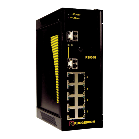
1.1 RS900G Family Front Panel Description Figure 1.1.1 RS900G Front Panel View ITEM Activity Comments LINK LED (Yellow) Solid Link Established Blinking Tx/Rx Activity Power LED Solid Power On Alarm LED Solid Alarm condition exists 2010 RuggedCom Inc. All rights reserved Rev105... -
Page 7: Rs900G Family Bottom View
1.2 RS900G Family Bottom View Figure 1.2.1 RS900G Family Bottom View 2010 RuggedCom Inc. All rights reserved Rev105... -
Page 8: Installation
2.1 DIN Rail Mounting An optional DIN rail mounting bracket is available for the RS900G. Figure 2.1.1 details mounting instructions for the standard 1” DIN Rail. Figure 2.1.1 RS900G Family DIN Rail Mounting 2010 RuggedCom Inc. All rights reserved Rev105... -
Page 9: Power Supply Wiring And Grounding
3. All line-to-ground transient energy is shunted to the Surge Ground terminal. In cases where users require the inputs to be isolated from ground, remove the ground braid between Surge and Chassis Ground. Note that all line-to-ground transient protection circuitry will be disabled. 2010 RuggedCom Inc. All rights reserved Rev105... -
Page 10: Dc Power Supply Wiring And Grounding
4. All line-to-ground transient energy is shunted to the Surge Ground terminal. In cases where users require the DC inputs to be isolated from ground, remove the ground braid between Surge and Chassis Ground. Note that all line-to-ground transient protection circuitry will be disabled. 2010 RuggedCom Inc. All rights reserved Rev105... -
Page 11: Hipot (Dielectric Strength) Testing
(see Figure 2.3.1) during the HIPOT test. This is required in order to prevent the transient/surge suppression circuitry, which is connected to Surge Ground (see Figure 2.3.1), from being activated during the HIPOT test. Figure 2.3.1 HIPOT (Dielectric Strength) Testing 2010 RuggedCom Inc. All rights reserved Rev105... -
Page 12: Failsafe Output Wiring And Specifications
The “Failsafe” output relay is provided to signal critical error conditions that may occur on the RS900G series switch. The contacts are energized upon power up of the unit and remain energized until an alarm condition or power loss occurs. Figure 2.4.1 RS900G Family Failsafe Output Relay 2010 RuggedCom Inc. All rights reserved Rev105... -
Page 13: Rs232 Port Wiring
No Connection No Connection Table 2.5.1 RS232 Female DCE pin-out NOTE: This port is not intended to be a permanent connection and the cable shall be less than 2m (6.5 ft) in length. 2010 RuggedCom Inc. All rights reserved Rev105... -
Page 14: Rj45 Ports - Signal Description
Case Shield (Chassis Ground) Fig. 2.6.1 shows the RJ45 port pins configuration. NOTE: RuggedCom does not recommend the use of CAT-5 cabling of any length for critical real- time substation automation applications. However, transient suppression circuitry is present on all copper ports to protect against damage from electrical transients and to ensure IEC 61850-3 and IEEE 1613 Class 1 conformance. -
Page 15: Technical Specifications
Parameter Value Max Switching Voltage 30VAC, 80VDC Rated Switching Current 0.3A @ 30VAC 1A @ 30VDC, 0.3A @ 80VDC Figure 1 - Failsafe Relay Specification NOTES: Resistive Load. For Class-2 circuits only. 2010 RuggedCom Inc. All rights reserved Rev105... -
Page 16: Twisted Pair Data Port Specifications
RJ45 3.5 Fiber Optical Port Specifications For maximum flexibility RuggedCom Inc. offers a number of different transceiver choices for Gigabit fiber optical communications. The following table details fiber optic specifications based on the order code / transceiver selected at time of ordering. -
Page 17: Physical Dimensions
3.6 Physical Dimensions Parameter Value Comments Dimensions 7,4 x 2,6 x 5,0 inches (Length x Width x Depth) (187,96) x (66,04) x (127,0) mm Weight 2.7 lb (1.2 Kg) Enclosure 20 AWG Galvanized Steel 2010 RuggedCom Inc. All rights reserved Rev105... -
Page 18: Type Tests
2kV AC (Fail-Safe Relay output) IEC 60255-5 Dielectric Strength D.C. Power ports 1.5kV DC A.C. Power ports 2kV AC Signal ports 5kV (Fail-Safe Relay output) IEC 60255-5 H.V. Impulse D.C. Power ports A.C. Power ports 2010 RuggedCom Inc. All rights reserved Rev105... -
Page 19: Ieee 1613 Type Tests
+85 deg. C, 16 Hours Humidity (Damp Heat, IEC 60068-2-30 Test Db 95% (non-condensing), 55°C, 6 cycles Cyclic) IEC 60255-21-1 Vibration 2g @ (10-150) Hz Class 2 IEC 60255-21-2 Shock 30g @ 11 ms Class 2 2010 RuggedCom Inc. All rights reserved Rev105... -
Page 20: Agency Approvals
Class 1, Division 2, Groups A, B, C,& D. Approved T6 rating at 40C, T4A rating at 85C 5 Warranty RuggedCom warrants this product for a period of five (5) years from date of purchase. For warranty details, visit http://www.ruggedcom.com or contact your customer service representative. Should this product require warranty or service, contact the factory at: RuggedCom Inc.
Need help?
Do you have a question about the RuggedSwitch RS900G and is the answer not in the manual?
Questions and answers