
Related Manuals for Lantech 5 10/100TX w/ 4 PoE Injector Industrial Switch


Summary of Contents for Lantech 5 10/100TX w/ 4 PoE Injector Industrial Switch
- Page 1 Lantech 5 10/100TX with 4 PoE Injector Industrial Switch User Manual V1.01 Nov-2007...
-
Page 2: Fcc Warning
FCC Warning This Equipment has been tested and found to comply with the limits for a Class-A digital device, pursuant to Part 15 of the FCC rules. These limits are designed to provide reasonable protection against harmful interference in a residential installation. This equipment generates, uses, and can radiate radio frequency energy. -
Page 3: Table Of Contents
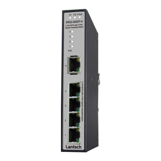
Content Introduction ..............1 Features ..............1 Package Contents ............ 2 Hardware Description ..........3 Physical Dimension ..........3 Front Panel .............. 3 Top View ..............4 LED Indicators ............5 Ports ................. 6 Cabling ..............7 Wiring the Power Inputs ........... 8 Wiring the Fault Alarm Contact ........ -
Page 4: Introduction
Introduction The 5 10/100TX w/ 4 PoE Injector Industrial Switch is a cost-effective solution and meets the high reliability requirements demanded by industrial applications. Besides, the industrial switch provides the PoE function for kinds of Powered Devices to receive power as well as data over the RJ-45 cable. -
Page 5: Package Contents
Package Contents Please refer to the package contents list below to verify them against the checklist. 5 10/100TX w/ 4 PoE Injector Industrial Switch User manual Pluggable Terminal Block 2 wall mount plates with screws Compare the contents of the industrial switch with the standard checklist above. If any... -
Page 6: Hardware Description
In this paragraph, the Industrial switch’s hardware spec, port, cabling information, and wiring installation will be described. Physical Dimension 5 10/100TX w/ 4 PoE Injector Industrial Switch dimension (W x D x H) is 30mm x 95mm x 140mm Front Panel... -
Page 7: Top View
Top View The top view of the 5 10/100TX w/ 4 PoE Injector Industrial Switch has one terminal block connector of two DC power inputs. Top View of the PoE Injectors Industrial Switch... -
Page 8: Led Indicators
LED Indicators The diagnostic LEDs located on the front panel of the industrial switch provide real-time information of system and optional status. The following table provides the description of the LED status and their meanings for the switch. Color Description Power input 1 is active Green Power input 1 is inactive... -
Page 9: Ports
Ports RJ-45 ports The UTP (RJ-45) Fast Ethernet ports will auto-sense for 10Base-T or 100Base-TX connections. Auto MDI/MDIX means that the switch can connect to another switch or workstation without changing straight through or crossover cabling. See the below figures for straight through and crossover cable schematic. RJ-45 Pin Assignments Pin Number Assignment... -
Page 10: Cabling
Straight Through Cable Schematic Cross Over Cable Schematic Cabling Twisted-pair segment can be connected with unshielded twisted pair (UTP) or shielded twisted pair (STP) cable. The cable must comply with the IEEE 802.3u 100Base TX standard for Category 5. The cable between the converter and the link partner (switch, hub, workstation, etc.) must be less than 100 meters (328 ft.) long. -
Page 11: Wiring The Power Inputs
Wiring the Power Inputs Please follow the steps below to insert the power wire. Insert the positive and negative wires into the V+ and V- contacts on the terminal block connector. Tighten the wire-clamp screws for preventing the wires from loosing. -
Page 12: Wiring The Fault Alarm Contact
Wiring the Fault Alarm Contact The fault alarm contact is in the middle of terminal block connector as the picture shows below. Inserting the wires, it will detect the fault status including power failure or port link failure (managed industrial switch only) and form an open circuit. An application example for the fault alarm contact is shown as below: Insert the wires into the fault alarm contact. -
Page 13: Mounting Installation
Mounting Installation DIN-Rail Mounting The DIN-Rail is screwed on the industrial switch when out of factory. If the DIN-Rail is not screwed on the industrial switch, please see the following pictures to screw the DIN- Rail on the switch. Follow the steps below to hang the industrial switch. Use the screws to screw the DIN-Rail on the rear side of the industrial switch. - Page 14 After the DIN-Rail is screwed on the rear side of the switch, insert the top of DIN- Rail into the track. Then, lightly push the DIN-Rail into the track. Check if the DIN-Rail is tightened on the track or not. To remove the industrial switch from the track, reverse steps above.
-
Page 15: Wall Mount Plate Mounting
Wall Mount Plate Mounting Follow the steps below to mount the industrial switch with wall mount plate. 1. Remove the DIN-Rail from the industrial switch; loose the screws to remove the DIN- Rail. 2. Place the wall mount plate on the rear panel of the industrial switch. 3. -
Page 16: Hardware Installation
Hardware Installation In this paragraph, we are going to mention how to install the 5 10/100TX w/ 4 PoE Injector Industrial Switch and the installation points to be attended to it. Installation Steps 1. Unpack the Industrial switch packing. 2. Check if the DIN-Rail is screwed on the Industrial switch or not. If the DIN-Rail is not screwed on the Industrial switch, please refer to DIN-Rail Mounting section for DIN- Rail installation. -
Page 17: Network Application
Network Application This segment provides the sample to help user have more actual idea of industrial switch application. For a sample application of the industrial switch, see the figure below. -
Page 18: Troubleshooting
Troubleshooting Verify that is using the right power cord/adapter (DC 48V), please don’t use the power adapter with DC output voltage higher than 48V, or it will burn this equipment down. Select the proper UTP/STP cable to construct your network. Please check that is using the right cable. -
Page 19: Technical Specification
Technical Specification The 5 10/100TX w/ 4 PoE Injector Industrial Switch technical specifications is shown as below. IEEE 802.3 10Base-T Ethernet IEEE 802.3u 100Base-TX Fast Ethernet Standard IEEE802.3x Flow Control and Back Pressure IEEE802.3af Power over Ethernet Protocol CSMA/CD 14,880 pps for 10Base-T Ethernet port... - Page 20 10Base-T: 2-pair UTP/STP Cat. 3, 4, 5, 5e cable EIA/TIA-568 100-ohm (100m) Network Cable 100Base-TX: 2-pair UTP/STP Cat. 5/5e cable EIA/TIA-568 100-ohm (100m) Redundant power DC 48V with connective removable Power Supply terminal block Power 3.4Watts (without PoE); 57 Watts (Full load with PoE) Consumption DIN rail kit for DIN-type cabinet install and wall-mount Installation...
Need help?
Do you have a question about the 5 10/100TX w/ 4 PoE Injector Industrial Switch and is the answer not in the manual?
Questions and answers