
Related Manuals for Lantech IPES-3408GSFP


Summary of Contents for Lantech IPES-3408GSFP
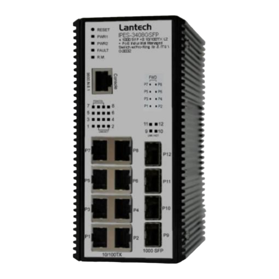
- Page 1 Lantech IPES-3408GSFP 4 1000 SFP +8 10/100TX L2 + PoE Industrial Managed Switch User Manual Beta.04 July. 2013...
- Page 2 Recommendation for Shielded network cables STP cables have additional shielding material that is used to reduce external interference. The shield also reduces the emission at any point in the path of the cable. Our recommendation is to deploy an STP network cable in demanding electrical environments. Examples of demanding indoor environments are where the network cable is located in parallel with electrical mains supply cables or where large inductive loads such as motors or contactors are in close vicinity to the camera or its cable.
-
Page 3: Fcc Warning
FCC Warning This Equipment has been tested and found to comply with the limits for a Class-A digital device, pursuant to Part 15 of the FCC rules. These limits are designed to provide reasonable protection against harmful interference in a residential installation. This equipment generates, uses, and can radiate radio frequency energy. -
Page 4: Chapter 1 Introduction
Chapter 1 Introduction The IPES-3408 series Managed Industrial Switch is a cost-effective solution and meets the high reliability requirements demanded by industrial applications. Using fiber port can extend the connection distance that increases the network elasticity and performance. 1.1 Hardware Features IEEE 802.3 10Base-T Ethernet IEEE 802.3u 100Base-TX IEEE802.3z Gigabit fiber... - Page 5 10/100TX: 8 x RJ-45 type connector Mini-GBIC: 4 x 1000 SFP Sockets Connector Power & P-Fail connector: 1 x 6-pole terminal block RS-232 connector: 1 x RJ-45 type connector 10Base-T: 2-pair UTP/STP Cat. 3, 4, 5 cable EIA/TIA-568 100-ohm (100m) Network Cable 100Base-TX: 2-pair UTP/STP Cat.
- Page 6 IEC60068-2-32 (Free fall), IEC60068-2-27 (Shock), Stability Testing IEC60068-2-6 (Vibration)
-
Page 7: Software Features
1.2 Software Features Management SNMP v1 v2c, v3/ Web/Telnet/CLI RFC 1215 Traps MIB, RFC 1213 MIBII, RFC 1157 SNMP MIB, RFC 1493 Bridge MIB, RFC 2674 VLAN MIB, SNMP MIB RFC 1643 EtherLike, RFC 1757 RMON, RSTP MIB, Private MIB, LLDP MIB Support ITU G.8032 v2 for Ring protection in less than 10ms for self-heal recovery <... - Page 8 Cisco Discovery Protocol for topology mapping PoE Detection to check if PD is hang up then restart Management the PD PoE Scheduling to On/OFF PD upon routine time table VLAN Port Based VLAN IEEE 802.1Q Tag VLAN (256 entries)/ VLAN ID (Up to 4K, VLAN ID can be assigned from 1 to 4096.) GVRP (256 Groups)*,GMRP*, MVRP (Multi VLAN Registeration)*, QinQ...
- Page 9 TACACS+ for Authentication* SMTP/Text SMS Supports SMTP Server and 6 e-mail accounts for receiving event alert; can send SMS text alert via mobile Spanning Tree Supports IEEE802.1d Spanning Tree and IEEE802.1w Rapid Spanning Tree, IEEE802.1s Multiple Spanning Tree The quality of service determined by port, Tag and IPv4 Quality of Service Type of service, IPv4 Different Service Supports IEEE802.1p class of service, per port provides 4...
- Page 10 the pull-down menu for the ingress packet filter and the egress packet limit. Built-in Real Time Clock to keep track of time always Supports Flow Control for Full-duplex and Back Pressure Flow Control for Half-duplex System Log Supports System log record and remote system log server Supports SMTP Server and 6 e-mail accounts for receiving SMTP event alert...
- Page 11 Each port allows an alphabetic string of 128-byte assigned ifAlias as its own unique name via the SNMP or CLI interface...
-
Page 12: Chapter 2 Hardware Description
Chapter 2 Hardware Description In this paragraph, it will describe the Industrial switch’s hardware spec, port, cabling information, and wiring installation. 2.1 Physical Dimension 65 (W) x 105 (D) x 152 (H) mm 2.2 Front Panel Front Panel of the industrial switch... -
Page 13: Top View
2.3 Top View The top panel of the Industrial Managed Industrial Switch has one terminal block connector of two DC power inputs and one fault alarm. Top Panel of the industrial switch... -
Page 14: Led Indicators
2.4 LED Indicators The diagnostic LEDs that provide real-time information of system and optional status are located on the front panel of the industrial switch. The following table provides the description of the LED status and their meanings for the switch. Color Status Meaning... -
Page 15: Chapter 3 Hardware Installation
Chapter 3 Hardware Installation In this paragraph, we will describe how to install the IPES-3408 series Managed Industrial Switch and the installation points attended to it. 3.1 Installation Steps 1. Unpack the Industrial switch 2. Check if the DIN-Rail is screwed on the Industrial switch or not. If the DIN-Rail is not screwed on the Industrial switch, please refer to DIN-Rail Mounting section for DIN- Rail installation. -
Page 16: Din-Rail Mounting
3.2 DIN-Rail Mounting The DIN-Rail is screwed on the industrial switch when out of factory. If the DIN-Rail is not screwed on the industrial switch, please see the following pictures to screw the DIN- Rail on the switch. Follow the steps below to hang the industrial switch. - Page 17 First, insert the top of DIN-Rail into the track. Then, lightly push the DIN-Rail into the track. Check if the DIN-Rail is tightened on the track or not. To remove the industrial switch from the track, reverse above steps.
-
Page 18: Wall Mount Plate Mounting
3.3 Wall Mount Plate Mounting Follow the steps below to mount the industrial switch with wall mount plate. 1. Remove the DIN-Rail from the industrial switch; loose the screws to remove the DIN- Rail. 2. Place the wall mount plate on the rear panel of the industrial switch. 3. -
Page 19: Wiring The Power Inputs
3.4 Wiring the Power Inputs Please follow the steps below to insert the power wire. 1. Insert AC or DC power wires into the contacts 1 and 2 for power 1, or 5 and 6 for power. 2. Tighten the wire-clamp screws for preventing the wires from loosing. [NOTE] The wire gauge for the terminal block should be in the range between 12 ~ 24 AWG. -
Page 20: Wiring The Fault Alarm Contact
3.5 Wiring the Fault Alarm Contact The fault alarm contacts are in the middle of the terminal block connector as the picture shows below. Inserting the wires, the switch will detect the fault status of the power failure, or port link failure (available for managed model) and then forms an open circuit. The following illustration shows an application example for wiring the fault alarm contacts. - Page 21 3.6 Cabling Use four twisted-pair, Category 5e or above cabling for RJ-45 port connection. The cable between the switch and the link partner (switch, hub, workstation, etc.) must be less than 100 meters (328 ft.) long. Fiber segment using single-mode connector type must use 9/125 µm single-mode fiber cable.
- Page 22 To connect the transceiver and LC cable, please follow the steps shown below: First, insert the transceiver into the SFP module. Notice that the triangle mark is the bottom of the module. Transceiver to the SFP module Transceiver Inserted Second, insert the fiber cable of LC connector into the transceiver.
- Page 23 LC connector to the transceiver...
- Page 24 To remove the LC connector from the transceiver, please follow the steps shown below: First, press the upper side of the LC connector to release from the transceiver and pull it out. Remove LC connector Second, push down the metal loop and pull the transceiver out by the plastic handle. Pull out from the transceiver...
-
Page 25: Chapter 4 Network Application
Chapter 4 Network Application This chapter provides some sample applications to help user to have more actual idea of industrial switch function application. A sample application of the industrial switch is as below:... -
Page 26: Itu G.8032 Scheme
4.1 ITU G.8032 Scheme Lantech G.8032 protocol is following ITU (International Telecommunication Unit) G.8032 v2 draft. The benefits of G.8032 are: 1. <50ms recovery time when failover 2. G.8032 is the standard protocol which can interact amongst different brands without being tie up by the same supplier to ensure the best investment 3. -
Page 27: Multiple Rings
2- Multiple Rings 2-1. Dual Rings 2-2. Multiple Rings 3- Dual Homing... - Page 28 4- Chain 4-1. Single Chain 4-2. Multiple Chains 4-3. Multiple Chains Share Common Ends 4-4. Cascade Chain...
- Page 29 4-5. Chain in Chain...
-
Page 30: Chapter 5 Console Management
Chapter 5 Console Management 5.1 Connecting to the Console Port The supplied cable which one end is RS-232 connector and the other end is RJ-45 connector. Attach the end of RS-232 connector to PC or terminal and the other end of RJ-45 connector to the console port of the switch. -
Page 31: Login In The Console Interface
5.3 Login in the Console Interface When the connection between Switch and PC is ready, turn on the PC and run a terminal emulation program or Hyper Terminal and configure its communication parameters to match the following default characteristics of the console port: Baud Rate:115200 bps Data Bits: 8 Parity: none... -
Page 32: Chapter 6 Web-Based Management
Chapter 6 Web-Based Management This section introduces the configuration and functions of the Web-Based management. 6.1 About Web-based Management There is an embedded HTML web site residing in flash memory on CPU board of the switch, which offers advanced management features and allows users to manage the switch from anywhere on the network through a standard browser such as Microsoft Internet Explorer. -
Page 33: System Login
6.3 System Login Launch the Internet Explorer on the PC Key in “http:// “+” the IP address of the switch”, and then Press “Enter”. The login screen will appear right after Key in the user name and password. The default user name and password are the same as ‘root’. - Page 34 6.4 System 6.4.1 System Identification Configuration Name: An administratively assigned name for this managed node. By convention, this is the node's fully-qualified domain name. A domain name is a text string drawn from the alphabet (A-Za-z), digits (0-9), minus sign (-). No space characters are permitted as part of a name.
- Page 35 6.4.2 Switch Information This function will show you the basic information of switch. 6.4.3 IP configuration DHSP client: Set the switch as DHCP client, it will get the IP address from DHCP server. IP Address: Input the IP address of switch IPV6 Address:...
- Page 36 You can input the IP address of IPV6 standard of switch in here. Network Mask: The network mask of IP address. Default Gateway: The IP address of network gateway, if you need switch to connect with internet, please input correct IP address. DNS Server IP: The IP address of DNS server, if you need switch to enable internet service (like SNTP), please input correct IP address.
- Page 37 Subnet Maske: Define the Subnet Mask which will be assigned to DHCP client. Gateway: Define the gateway which will be assigned to DHCP client. DNS: Define the DNS which will be assigned to DHCP client. Lease Time: Define the effective time of assigned IP address, the DHCP client will apply the IP again from DHCP server when the time is over.
- Page 38 Local Time Zone Conversion from UTC Time at 12:00 UTC November Time Zone - 1 hour 11am Oscar Time Zone -2 hours 10 am ADT - Atlantic Daylight -3 hours 9 am AST - Atlantic Standard -4 hours 8 am EDT - Eastern Daylight EST - Eastern Standard -5 hours...
- Page 39 BT - Baghdad, USSR +3 hours 3 pm Zone 2 ZP4 - USSR Zone 3 +4 hours 4 pm ZP5 - USSR Zone 4 +5 hours 5 pm ZP6 - USSR Zone 5 +6 hours 6 pm WAST - West Australian +7 hours 7 pm Standard...
- Page 40 SNMP Configuration Community Agent version: Choose the SNMP V1 or V2c or V3 String: Set the community string of SNMP protocol with read only persimission or read/write permission.
- Page 41 TRAP IP address: The IP address of trap destination (usually will be the PC of manager). Community: The community string of SNMP trap. Version: Select the SNMP trap version. V3 User User name: Set the user name. Security Level: Set up the access level, you can choose Authentication or Privacy or Both. Authentication Protocol: Set the authenticated way, the default value was MD5 Authentication Password:...
- Page 42 Set the password of Privacy. 6.4.6 System Event Log View Logs Logs The action of the system log entry. The following action types are supported: <0> Login: User Login. <1> Boot: System Boot. <2> Din: Din Event is triggered. <3> Link Change: Link change. <4>...
- Page 43 Local Log Action Save to Local: Save log to local file Remote Syslog Action Log to Remote Syslog Server: Save log to Syslog Server Email Action Email Alert: Sent log via Email...
- Page 44 SMS Action SMS Alert: Sent log via SMS service. (The user must let the switch connect with internet and define the SMS server then the user can use this function) Event Action Map Event Actions Select an Event to Add.
- Page 45 <0> Login: User Login. <1> Boot: System Boot. <2> Din1: Din Event 1 is triggered. <3> Din2: Din Event 2 is triggered. <4> Power1: Power 1 conditions. <5> Power2: Power 2 conditions. Link Event Actions Select an Event to Add. Fault Relay Configuration Configure Fault Relay on this page.
- Page 46 6.4.7 Digital Input / Output Configuration This device contains two digital outputs and two digital inputs. Outputs are open- collector transistor switches that may be controlled by the host computer. They provide messages, which can be applied to heaters, pumps, and other electrical equipment.
- Page 47 Digital Output When First/Second Digital Output function is enabled, First Digital Output/Second Digital Output will then be available respectively. Action: Choose the output type of electrical signal. Low->High: Having focused this radio button, DO0/DO1 will output an electrical signal of Low-to-High when the condition of the ticked checkbox is met (port/power failure occurs).
- Page 48 6.5 Ports 6.5.1 Port Configuration This page displays current port configurations. Ports can also be configured here. The port settings relate to the currently selected stack unit, as reflected by the page header. This is the logical port number for this row.
- Page 49 Description: Enter up to 47 characters to be descriptive name for identifies this port. Enabled: The port can be set to disable or enable mode. If the port setting is disable then will not receive or transmit any packet. Flow Control: set flow control function of the port.
- Page 50 Port No: This is the logical port number for this row. Type: This is the logical port type. Link Status: The current link state is displayed graphically. Green indicates the link is up and red that it is down. Speed: Provides the current link speed of the port.
- Page 51 The counts of receiving good packets (including undersize [less than 64 octets], oversize, CRC error, fragments and jabbers) via this port. Tx Abort Packet: The aborted packet while transmitting. Packet Collision: The counts of collision packet. Packet Dropped: The counts of dropped packet. Rx Bcast Packet: The counts of broadcast packet.
- Page 52 Port Rate Limiting You can set up every port's bandwidth rate and frame limitation type. Ingress Limit Frame type: select the frame type that wants to filter. The frame types have 4 options for selecting: All, broadcast/multicast/flooded unicast, broadcast/multicast, and broadcast only. These 4 types are only for ingress packet. The egress rate only supports all type packets.
-
Page 53: Power Over Ethernet
6.6 Power over Ethernet Maximum Power Available: This function can limit the total power consumption, please don’t over 250W. Port No. The number of each PoE port Enable Enable/disable the PoE function of each PoE port Priority Set the priority of power supply, if the total power consumption of all PoE ports was over the value of maximum power available, the switch will offer the power to the high priority PoE port and stop to supply power to the low priority PoE port. - Page 54 Power Consumption: Total power consumption of all PoE ports Main Voltage: The output voltage of each PoE port. Main Current The output current of each PoE port. Port No. The number of each PoE port. Link The connection status of each PoE port. State The PoE status of the ending device.(Unknown means the ending device was none- PD device)
- Page 55 Output current of each PoE port Voltage Output Voltage of each PoE port Power Power consumption of each PoE port Detection Class The PoE class of each PD device which connect with switch.
- Page 56 6.7 Topology This function can help the user build the network topology drawing of field in switch, please remember to enable LLDP function before you using this application. Topology Status Text View: Display each switch in your network by text. The Topology was build with the information from LLDP, this function can let you see the information of LLDP from other switches.
- Page 57 Graphic View: Display each switch in your network by graphic. You can see the topology diagram which build by the LLDP information in here.
- Page 58 Demo: Demo display each topology in different application.
- Page 59 6.8 QoS QoS Policy Using the weight fair queue scheme the switch will follow 1:1 rate to process priority queue from High to lowest queue. Priority Type Port-base: the port priority will follow the default port priority that you have assigned - High, center, low, or lowest.
- Page 60 only. When the packet received by port 1, the system will check the ToS value of the received IP packet. If the ToS value of received IP packet is 25(priority = 7), and then the packet priority will have highest priority. 6.9 Security 6.9.1 MAC Address Tables Use the MAC address table to ensure the port security.
- Page 61 ou can view the port that connected device's MAC address and related device's MAC address. 6.9.2 Access Control List You can use ACL feature to deny the access from the specified IP address or MAC address. 6.9.2.1 ACL with Layer2 (MAC) No: The number of ACL record.
- Page 62 6.9.3 IEEE 802.1X Radius Server 802.1X makes use of the physical access characteristics of IEEE802 LAN infrastructures in order to provide a means of authenticating and authorizing devices attached to a LAN port that has point-to-point connection characteristics, and of preventing access to that port in cases in which the authentication and authorization process fails.
- Page 63 6.9.4 IP Security Help IP security function allows user to assign 20 specific IP addresses that have permission to access the switch through the web browser for the securing switch management. Enable IP Security When this option is in Enable mode, the Enable Web Server and Enable Telnet Server and Enable SSH Server check boxes will then be available.
- Page 64 6.10.VLAN The VLAN membership configuration for the switch can be monitored and modified here. Up to 4094 VLANs are supported. This page allows for adding and deleting VLANs as well as adding and deleting port members of each VLAN. 802.1Q VLAN Config Link Type: There are 3 types of link type.
- Page 65 2. Trunk Link: A segment which provides the link path for one or more VLAN- aware devices (switches). A Trunk Port, connected to the trunk link, has an understanding of tagged frame, which is used for the communication among VLANs across switches. Which frames of the specified VIDs will be forwarded depends on the values filled in the Tagged VID column field.
- Page 66 802.1Q VLAN Status You can see the status of each VLAN group in here. 6.11.MVR The MVR feature enables multicast traffic forwarding on the Multicast VLAN. In a multicast television application, a PC or a television with a set-top box can receive the multicast stream.
- Page 67 6.12.LLDP 6.12.1 LLDP Configuration Enabled Enabled The switch will send out LLDP information, and will analyze LLDP information received from neighbours. Tx Interval The switch periodically transmits LLDP frames to its neighbours for having the network discovery information up-to-date. The interval between each LLDP frame is determined by the Tx Interval value.
- Page 68 received from neighbors. 6.12.2. LLDP Neighbor This page provides a status overview for all LLDP neighbors. The displayed table contains a row for each port on which an LLDP neighbor is detected. The columns hold the following information: Local Port The port on which the LLDP frame was received.
- Page 69 5. Router 6. Telephone 7. DOCSIS cable device 8. Station only 9. Reserved When a capability is enabled, the capability is followed by (+). If the capability is disabled, the capability is followed by (-). Management Address Management Address is the neighbor unit's address that is used for higher layer entities to assist discovery by the network management.
- Page 70 Shows the number of new entries added since switch reboot. Neighbours Deleted Shows the number of new entries deleted since switch reboot. Frames Discarded If an LLDP frame is received on a port, and the switch's internal table has run full, the LLDP frame is counted and discarded.
- Page 71 LLDP frame is counted and discarded. This situation is known as "Too Many Neighbors" in the LLDP standard. LLDP frames require a new entry in the table when the Chassis ID or Remote Port ID is not already contained within the table. Entries are removed from the table when a given port's link is down, an LLDP shutdown frame is received, or when the entry ages out.
-
Page 72: Igmp Snooping
6.13 IGMP Snooping This page provides IGMP Snooping related configuration. Notice1: if the IP-CAM use Multicast format to transfer video stream, make sure there is at least one switch has enabled IGMP Querier function and all switches have enabled IGMP snooping function in field. Notice2: make sure the IGMP querier switch was in root side of your network, if not, please set IGMP router port to let switch know which uplink connection was dedicate to the path to the IGMP querior switch. - Page 73 Port Related Configuration Port The switch port number of the logical port. Router Port Specify which ports act as router ports. A router port is a port on the Ethernet switch that leads towards the Layer 3 multicast device or IGMP querier. If an aggregation member port is selected as a router port, the whole aggregation will act as a router port.
- Page 74 Status Querier Shows the Querier status is "ACTIVE" or "IDLE". "DISABLE" denotes the specific interface is administratively disabled. Queries Transmitted The number of Transmitted Queries. Queries Received The number of Received Queries. V1 Reports Received The number of Received V1 Reports. V2 Reports Received The number of Received V2 Reports.
- Page 75 Ports under this group. Membership Interval The group hold aging out TTL 6.14 CDP 6.14.1 CDP Configuration Device Settings CDP Enabled Enabled The switch will send out CDP information, and will analyze CDP information received from neighbors. Tx Interval(secs) The switch periodically transmits CDP frames to its neighbours for having the network discovery information up-to-date.
- Page 76 CDP Port Configuration The CDP port settings relate to the currently selected stack unit, as reflected by the page header. Port The switch port number of the logical CDP port. Enabled The switch will send out CDP information, and will analyze CDP information received from neighbors.
- Page 77 detected. The columns hold the following information: Local Port The port on which the CDP frame was received. Version Version is the CDP version advertised by the neighbor unit. Ageout TTL Ageout TTL is the ageout Time-To-Live advertised by the neighbor unit. Device ID The Device ID is the identification of the neighbor's CDP frames.
- Page 78 6.14 MSTP 6.14.1. MSTP Global Configuration Mode You can choose STP or RSTP or MSTP redundancy protocol in here. Name The name identifying the VLAN to MSTI mapping. Bridges must share the name and revision (see below), as well as the VLAN-to-MSTI mapping configuration in order to share spanning trees for MSTI's (Intra-region).
- Page 79 Max Age The maximum age of the information transmitted by the Bridge when it is the Root Bridge. Valid values are in the range 6 to 40 seconds, and MaxAge must be <= (FwdDelay-1)*2. Maximum Hop Count This defines the initial value of remaining Hops for MSTI information generated at the boundary of an MSTI region.
- Page 80 6.14.1.3 Remember to press “Apply” 6.14.1.4 Save setting 6.14.2 CIST Settings Bridge configuration VLANs Mapped The list of VLANs mapped to the MSTI. The VLANs must be separated with comma...
- Page 81 and/or space. A VLAN can only be mapped to one MSTI. An unused MSTI should just be left empty. (I.e. not having any VLANs mapped to it.) Unmapped VLANs are mapped to the CIST. (The default bridge instance). Bridge Priority Controls the bridge priority.
- Page 82 p2p_mode description: Controls whether the port connects to a point-to-point LAN rather than a shared medium. This can be automatically determined, or forced either true or false. Transition to the forwarding state is faster for point-to-point LANs than for shared media.
- Page 83 6.14.4. MSTP Bridges Status Instance The Bridge Instance. ex: CIST, MSTI1, ... Bridge ID The Bridge ID of this Bridge instance. Root ID The Bridge ID of the currently elected root bridge. Root Port The switch port currently assigned the root port role. Root Cost Root Path Cost.
-
Page 84: Bridge Status Of All Ports
6.14.5. Bridge status of all ports Port The switch port number of the logical STP port. Role The current STP port role of the port. The port role can be one of the following values: AlternatePort BackupPort RootPort DesignatedPort Disabled. State The current STP port state of the port. - Page 85 6.15 Aggregation 6.15.1. Aggregation Configuration Group Configuration Trunking Group Number of trunking group Enable LACP Dynamic Trunking: Enable Trunking function Port Members Each switch port is listed for each group ID. Select a radio button to include a port in an aggregation, or clear the radio button to remove the port from the aggregation.
- Page 86 6.15.2 LACP Port Status Trunking Group Number of trunking group LACP 'Yes' means that LACP is enabled and the port link is up. 'No' means that LACP is not enabled or that the port link is down. 'Backup' means that the port could not join the aggregation group but will join if other port leaves.
- Page 87 6.16 PTP Enable on: Select which port you want to enable PTP function. Domain: Set the PTP domain Priority1: Specify the priority1 value to override the default criteria (clock quality, clock class, etc.) for best master clock selection. Lower values take precedence.The range for both is from 0 to 255., The default is 255 Priority2: Specify a priority2 value to be used as a tie-breaker between two devices that are...
- Page 88 Sync Interval: enter the time for sending synchronization messages. The range is -1 second to 1 second. The default is 1 second. Delay Request Interval: specify the time recommended to the member devices to send delay request messages when the port is in the master state. The range is -1 second to 6 seconds. The default is 1 (2 seconds).
- Page 89 6.17 G.8032 ERPS 6.17.1. G.8032 Ethernet Ring Protection Configuration The G.8032 Ethernet Ring Protection Switch instances are configured here. The ID of the created Protection group Enabled Enable/Disable the G.8032 ERP. Role It can be either RPL owner or RPL Neighbor. Type Type of Protecting ring.
- Page 90 6.16.1.3 Enter edit mode 6.16.1.4 There are 3 switches in the ring of G.8032, one play the role of “owner”, one “neighbour” “none” , and one for remember 3 very import things during the setting procedure: the port0 of “owner” switch must connect with the “neighbour” 6.16.1.5 switch.
- Page 91 6.16.1.8 The setting of neighbour switch 6.16.1.9 The setting of none switch...
- Page 92 6.16.2. Ring Status Help The ID of the created Protection group State ERPS state according to State Transition Tables in G.8032. Role It can be either RPL owner or RPL Neighbour. Ring Port 0 true : ring port 0 is blocking false : ring port 0 is not blocking Ring Port 1 true : ring port 0 is blocking...
-
Page 93: Maintenance
6.178Maintenance 6.18.1 Save Configuration Save setting of switch 6.18.2 Config backup/restore Settings Backup You can download the backup configuration of the switch. Settings Restore You can copy the backup configuration of the switch to the startup configuration on this page. The new startup configuration is not available immediately, which means that restart the switch is necessary. - Page 94 Reset to default You can reset the configuration of the switch on this page. Only the IP configuration is retained. The new configuration is available immediately, which means that no res tart is necessary. 6.18.3 Restart device Reboot the switch with selected firmware.
- Page 95 6.18.4 Firmware Upgrade Update the switch with the firmware file which on your desktop. 6.18.5 Diagnostics PING Address: Set the IP address which you want to ping Count: Set the times of Ping Packet Size: set the size of Ping packet.
- Page 96 ARP Table You can find the MAC addrees of each IP you have ping via this switch in here.
-
Page 97: Troubles Shooting
Troubles shooting Verify that is using the right power cord/adapter (DC 24-48V), please don’t use the power adapter with DC output higher than 48V, or it may damage this device. Select the proper UTP/STP cable to construct the user network. Use unshielded twisted-pair (UTP) or shield twisted-pair (STP) cable for RJ-45 connections that depend on the connector type the switch equipped: 100Ω... -
Page 98: Appendix A-Rj-45 Pin Assignment
Appendix A—RJ-45 Pin Assignment RJ-45 Pin Assignments The UTP/STP ports will automatically sense for Fast Ethernet (10Base-T/100Base-TX connections), or Gigabit Ethernet (10Base-T/100Base-TX/1000Base-T connections). Auto MDI/MDIX means that the switch can connect to another switch or workstation without changing straight through or crossover cabling. See the figures below for straight through and crossover cable schematic. - Page 99 10/100Base-TX Cable Schematic The following two figures show the 10/100Base-TX cable schematic. Straight-through cable schematic Cross over cable schematic 10/100/1000Base-TX Pin outs The following figure shows the 10/100/1000 Ethernet RJ-45 pin outs. 10/100/1000Base-TX Cable Schematic...
- Page 100 Straight through cables schematic Cross over cables schematic...
-
Page 101: Appendix B-Command Line Mode
Appendix B—Command Line mode Except the web acess mode, the Lantech switch also support Telnet access and console access mode, to compare the web access mode, both the Telnet and console only support command line user interface, all these commands will show as below: 1. - Page 102 Password (use Enter key to switch), then press Enter and the Main Menu of console management appears. Please see below figure for login screen. Notice: if you forgot the password, you can access the switch via console port and input lantech/lantech to restore the password to default.
-
Page 103: Access Via Telnet
2. Access via Telnet Use Telnet utility to access switch IP and make sure the socket was set as 23, all the commands under Telnet mode were the same as the Console mode. 3. Commands 3.1 System Command: system Parameter: N/A Description: Enter the system mode Example:... - Page 104 3.1.1 Command: system> configuration Parameter: N/A Description: show the information of switch Example:...
- Page 105 3.1.2 Command: system > Contact Parameter: N/A Description: display or fix the contact information Example: if I want to change the contact windows to jacky@lantechcom.tw 3.1.3 Command: system > name Parameter: N/A Description: display or fix the system name Example: 3.1.4 Command: system >...
- Page 106 3.1.6 Command: system > DHCPclient Parameter: enable/disable Description: enable or disable DHCP client Example: 3.1.7 Command: system > DHCP server Parameter: [enable|disable] enable or disable DHCP server [<range_low>]/[<range_high>] set the IP range [<netmask>] set submask [<gateway>] set gateway [<dns>] set DNS server [<lease_time>]...
- Page 107 3.1.9 Command: system > netstatus Parameter: N/A Description: show the status about IP address Example: 3.1.10 Command: system > netsettingIPv4 Parameter: [<IpAddr>] set IP address [<netmask>] set netmask [<gatewayip>] set gateway [<dnsip>] set DNS server Description: set the IP detail of switch Example: 3.1.11 Command: system >...
- Page 108 3.1.12 Command: system > reboot Parameter: N/A Description: reboot the switch Example: 3.1.13 Command: system > restoredefault Parameter: keep_none restore all setting keep_all restore all but keep original IP address and account keep_ip restore all but keep original IP address keep_account ...
- Page 109 3.1.16 Command: system > ping Parameter; N/A Description: ping the IP address Example: 3.1.17 Command: system > arp Parameter: N/A Description: resolve the IP address to MAC address Example: 3.1.18 Command: system > memory Parameter: N/A Description: display the status of used switch memory Example: 3.1.19 Command: system >...
- Page 110 3.1.20 Command: system > upgrade Parameter: [URL] set the source of firmware file, support TFTP and FTP and HTTP protocol. Description: update switch firmware Example: LLDP Command: LLDP Parameter: N/A Description: Enter the LLDP mode Example: 3.2.1 Command: LLDP > configuration Parameter: N/A Description: display the LLDP information Example:...
- Page 111 3.2.2 Command: LLDP > enabled Parameter: N/A Description: enable LLDP protocol Example: 3.2.3 Command: LLDP > mode Parameter: [<port_list>]display LLDP information of the dedicated port [enabledRxTx] enable Tx and Rx of LLDP function with dedicated port [enabledTxOnly] enable Tx only of LLDP function with dedicated port [enabledRxOnly]...
- Page 112 3.2.4 Command: LLDP > interval Parameter: N/A Description: set the interval time of LLDP Example: 3.2.5 Command: LLDP > timetolive Parameter: N/A Description: display the alive time of LLDP information. Example: 3.2.6 Command: LLDP > info Parameter: N/A Description: display the LLDP information of neighbor port Example:...
- Page 113 3.2.7 Command: LLDP > statistics Parameter: N/A Description: display the detail information of LLDP settings Example: Port Command: port Parameter: N/A Description: Enter the port mode Example:...
- Page 114 3.3.1 Command: port > configuration Parameter: N/A Description: display the setting of each port Example: 3.3.2 Command: port > status Parameter: N/A Description: display the connection status of each port Example:...
- Page 115 3.3.3 Command: port > enabled Parameter: [<port_list>] choose which port you want to enable or diasble [enable|disable] enable/disable Description: enable or disable switch port Example: 3.3.4 Command: port > description Parameter: N/A Description: display the description of each port Example:...
- Page 116 3.3.5 Command: port > speed Parameter: N/A Description: display the speed of each port Example: 3.3.6 Command: port > flowcontrol Parameter: [<port_list>] choose which port you want to enable or diasble [enable|disable] enable/disable Description: enable or disable flow control function of each port Example:...
- Page 117 3.3.7 Command: port > Ingressrate Parameter: [<port_list>] choose which port you want to set the ingress rate [<rate> kbps]set the ingress rate of these packet as below broadcast multicast unicast broad_uni broad_multi multi_uni uni_broad_multi Description: set the ingress rate of the dedicated port with specified packet Example:...
- Page 118 3.3.8 Command: port > egressrate Parameter: [<port_list>] choose which port you want to set the ingress rate [<rate> kbps]set the ingress rate Description: set the egress rate of the dedicated port Example: 3.3.9 Command: port > statistics Parameter: N/A Description: display the detail information of port statistics Example:...
Need help?
Do you have a question about the IPES-3408GSFP and is the answer not in the manual?
Questions and answers