
Related Manuals for Lantech IES-2208C


Summary of Contents for Lantech IES-2208C
- Page 1 Lantech IES-2208C/E 8 10/100TX + 2 10/100/1000T/Mini-GBIC Combo with X-Ring L2 anaged Industrial Switch User Manual...
- Page 2 This manual contents are based on the below table listing software kernel version, hardware version, and firmware version. If the switch functions have any different from the manual contents description, please contact the local sale dealer for more information. Firmware Version V1.13 Kernel Version V1.40...
- Page 3 FCC Warning This Equipment has been tested and found to comply with the limits for a Class-A digital device, pursuant to Part 15 of the FCC rules. These limits are designed to provide reasonable protection against harmful interference in a residential installation. This equipment generates uses and can radiate radio frequency energy and, if not installed and used in accordance with the instructions, may cause harmful interference to radio communications.
-
Page 4: Table Of Contents
Content Introduction ..............1 Features ..............1 Package Contents ............ 3 Hardware Description ..........4 Physical Dimension ..........4 Front Panel .............. 4 Top View ..............5 LED Indicators ............5 Ports ................. 7 Cabling ..............12 Wiring the Power Inputs ......... 13 Wiring the Fault Alarm Contact ...... - Page 5 Login in the Console Interface ....... 24 CLI Management ........... 25 Commands Level ............26 Commands Set List............27 System Commands Set ..........27 Port Commands Set ............30 Trunk Commands Set ............. 32 VLAN Commands Set ............. 33 Spanning Tree Commands Set ........35 QOS Commands Set ............
- Page 6 DHCP Client – System Configuration ....56 DHCP Server - Port and IP Bindings ..... 57 TFTP - Update Firmware ........57 TFTP – Restore Configuration ....... 58 TFTP - Backup Configuration ........ 58 System Event Log – Syslog Configuration ..... 59 System Event Log - SMTP Configuration ....
- Page 7 SNMP Configuration ..........84 System Configuration ............84 Trap Configuration ............85 SNMPV3 Configuration ........... 86 QoS Configuration ..........89 QoS Policy and Priority Type .......... 89 Port Base Priority ............90 COS Configuration ............91 TOS Configuration ............91 IGMP Configuration ..........
-
Page 8: Introduction
Introduction The 8 10/100TX + 2 10/100/1000T/Mini-GBIC Combo with X-Ring L2 Managed Industrial Switch is a cost-effective solution and meets the high reliability requirements demanded by industrial applications. The 8 10/100TX + 2 10/100/1000T/Mini-GBIC Combo with X-Ring L2 Managed Industrial Switch can be easily managed through the Web GUI. - Page 9 QoS (Quality of Service) Support IEEE 802.1p Class of Service, Per port provides 4 priority queues Port Base, Tag Base and Type of Service Priority Port Mirror: Monitor traffic in switched networks. TX Packet only ...
-
Page 10: Package Contents
X-ring topology changed Port Link up/Link down TFTP Firmware Update and System Configuration Restore and Backup Package Contents Please refer to the package content list below to verify them against the checklist. 8 10/100TX + 2 10/100/1000T/Mini-GBIC Combo with X-Ring L2 Managed Industrial Switch ... -
Page 11: Hardware Description
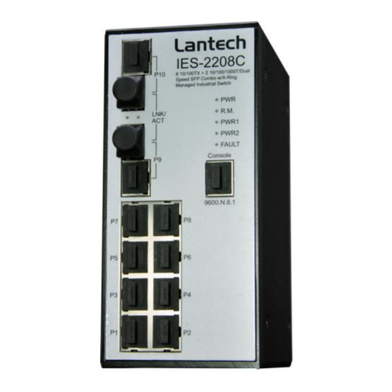
Hardware Description In this paragraph, it will describe the Industrial switch’s hardware spec, port, cabling information, and wiring installation. Physical Dimension 8 10/100TX + 2 10/100/1000T/Mini-GBIC Combo with X-Ring L2 Managed Industrial Switch dimension (W x D x H) is 72mm x 105mm x 152mm Front Panel The Front Panel of the 8 10/100TX + 2 10/100/1000T/Mini-GBIC Combo with X-Ring L2 Managed Industrial Switch is showed as below:... -
Page 12: Top View
Top View The top panel of the 8 10/100TX + 2 10/100/1000T/Mini-GBIC Combo with X-Ring L2 Managed Industrial Switch has one terminal block connector of two DC power inputs. Top Panel of the industrial switch LED Indicators The diagnostic LEDs located on the front panel of the industrial switch. They provide real-time information of system and optional status. - Page 13 No power inputs Power failure or UTP port failure or Fiber port failure Fault No Power failure or UTP port failure or Fiber port failure occurs The industrial switch is the master of Green the X-Ring group R.M. The industrial switch is not a ring master in the X-Ring group Green SFP port is linking...
-
Page 14: Ports
No device attached (Upper LED) Yellow The port is operating in full-duplex mode (Lower LED) Blinking Collision of Packets occurs (Lower LED) The port is in half-duplex mode or no (Lower LED) device attached Ports RJ-45 ports The 10/100Mbps UTP/STP ports will auto-sense for 10Base-T or 100Base-TX connections. - Page 15 cable. The table below shows the 10BASE-T/100BASE-TX MDI and MDI-X port pin outs. Pin MDI-X Signal Name MDI Signal Name Receive Data plus (RD+) Transmit Data plus (TD+) Receive Data minus (RD-) Transmit Data minus (TD-) Transmit Data plus (TD+) Receive Data plus (RD+) Transmit Data minus (TD-) Receive Data minus (RD-)
- Page 16 To connect the transceiver and LC cable, please follow the steps shown below: First, insert the transceiver into the SFP module. Notice that the triangle mark is the bottom of the module. Figure 2.8: Transceiver to the SFP module Figure 2.9: Transceiver Inserted...
- Page 17 Second, insert the fiber cable of LC connector into the transceiver. Figure 2.10: LC connector to the transceiver...
- Page 18 To remove the LC connector from the transceiver, please follow the steps shown below: First, press the upper side of the LC connector to release from the transceiver and pull it out. Figure 2.11: Remove LC connector Second, push down the metal loop and pull the transceiver out by the plastic handle. Figure 2.12: Pull out from the transceiver...
-
Page 19: Cabling
Cabling Using four twisted-pair, Category 5e or above cabling for RJ-45 port connection. The cable between the converter and the link partner (switch, hub, workstation, etc.) must be less than 100 meters (328 ft.) long. Fiber segment using single-mode connector type must use 9/125 µm single-mode fiber cable. -
Page 20: Wiring The Power Inputs
Wiring the Power Inputs Please follow the below steps to insert the power wire. V- V+ V- V+ 1. Insert the positive and negative wires into the V+ and V- contacts on the terminal block connector. 2. To tighten the wire-clamp screws for preventing the DC wires to loose. -
Page 21: Wiring The Fault Alarm Contact
Wiring the Fault Alarm Contact The fault alarm contact is in the middle of terminal block connector as below picture shows. By inserting the wires, it will detect the fault status which the power is failure or port link failure and form an open circuit. And, application example for the fault alarm contact as below: 1A@24V Insert the wires into the fault alarm contact... -
Page 22: Mounting Installation
Mounting Installation DIN-Rail Mounting The DIN-Rail is screwed on the industrial switch when out of factory. If the DIN-Rail is not screwed on the industrial switch, please see the following pictures to screw the DIN- Rail on the switch. Follow the below steps to hang the industrial switch. Rear Panel of the switch DIN-Rail... - Page 23 First, insert the top of DIN-Rail into the track. Then, lightly push the DIN-Rail into the track. Check if the DIN-Rail is tightened on the track or not. To remove the industrial switch from the track, reverse steps above.
-
Page 24: Wall Mount Plate Mounting
Wall Mount Plate Mounting Follow the steps below to mount the industrial switch with wall mount plate. 1. Remove the DIN-Rail from the industrial switch; loose the screws to remove the DIN- Rail. 2. Place the wall mount plate on the rear panel of the industrial switch. 3. -
Page 25: Hardware Installation
Hardware Installation In this paragraph, we will describe how to install the 8 10/100TX + 2 10/100/1000T/Mini- GBIC Combo with X-Ring L2 Managed Industrial Switch and the installation points to be attended to it. Installation Steps 1. Unpack the Industrial switch 2. -
Page 26: Network Application
Network Application This chapter provides some sample applications to help user to have more actual idea of industrial switch function application. A sample application of the industrial switch is as below:... -
Page 27: X-Ring Application
X-Ring Application The industrial switch supports the X-Ring protocol that can help the network system to recover from network connection failure within 300ms or less, and make the network system more reliable. The X-Ring algorithm is similar to Spanning Tree Protocol (STP) and Rapid STP (RSTP) algorithm but its recovery time is less than STP/RSTP. -
Page 28: Coupling Ring Application
Coupling Ring Application In the network, it may have more than one X-Ring group. Using the coupling ring function can connect each X-Ring for the redundant backup. It can ensure the transmissions between two ring groups not to fail. The following figure is a sample of coupling ring application. -
Page 29: Dual Homing Application
Dual Homing Application Dual Homing function is to prevent the connection loss from between X-Ring group and upper level/core switch. Assign two ports to be the Dual Homing port that is backup port in the X-Ring group. The Dual Homing function only works when the X-Ring function is active. -
Page 30: Console Management
Console Management Connecting to the Console Port The supplied cable which one end is RS-232 connector and the other end is RJ-45 connector. Attach the end of RS-232 connector to PC or terminal and the other end of RJ-45 connector to the console port of switch. The connected terminal or PC must support the terminal emulation program. -
Page 31: Login In The Console Interface
Login in the Console Interface When the connection between Switch and PC is ready, turn on the PC and run a terminal emulation program or Hyper Terminal and configure its communication parameters to match the following default characteristics of the console port: Baud Rate: 9600 bps Data Bits: 8 Parity: none... -
Page 32: Cli Management
Console login interface CLI Management The system supports the console management – CLI command. After you login to the system, you will see a command prompt. To enter CLI management interface, type in ‘enable’ command. CLI command interface... -
Page 33: Commands Level
The following table lists the CLI commands and description. Commands Level Access Exit Modes Prompt About This Mode1 Method Method The user commands available at the user level are a subset of Begin a those available at the Enter logout User EXEC session with switch>... -
Page 34: Commands Set List
while in exit. privileged EXEC mode. Enter the To exit to interface of global fast Ethernet configuratio command n mode, Use this mode to Interface (with a switch enter exit. configure parameters configuration specific (config-if)# To exist to for the switch and interface) privileged Ethernet ports. - Page 35 [System Description] description string description xxx system contact Set switch system switch(config)#system contact [System Contact] contact window string show system-info Show system switch>show system-info information ip address Configure the IP switch(config)#ip address [Ip-address] [Subnet- address of switch 192.168.16.1 255.255.255.0 mask] [Gateway] 192.168.16.254 ip dhcp Enable DHCP client...
- Page 36 dhcpserver dnsip Configure DNS IP for switch(config)#dhcpserver dnsip [DNS IP] DHCP clients 192.168.1.1 dhcpserver leasetime Configure lease time switch(config)#dhcpserver [Hours] (in hour) leasetime 1 dhcpserver ipbinding Set static IP for DHCP switch(config)#interface [IP address] clients by port fastEthernet 2 switch(config)#dhcpserver ipbinding 192.168.1.1 show dhcpserver Show configuration of...
-
Page 37: Port Commands Set
telnet server Port Commands Set Netstar Commands Level Description Example interface fastEthernet Choose the port for switch(config)#interface [Portid] modification. fastEthernet 2 duplex Use the duplex switch(config)#interface [full | half] configuration fastEthernet 2 command to specify switch(config-if)#duplex full the duplex mode of operation for Fast Ethernet. - Page 38 bandwidth type Set interface ingress switch(config)#interface broadcast-multicast- limit frame type to fastEthernet 2 ‘accept broadcast, flooded-unicast switch(config-if)#bandwidth type multicast, and flooded broadcast-multicast-flooded- unicast frame’ unicast bandwidth type Set interface ingress switch(config)#interface broadcast-multicast limit frame type to fastEthernet 2 ‘accept broadcast and switch(config-if)#bandwidth type multicast frame’...
-
Page 39: Trunk Commands Set
state Use the state interface switch(config)#interface [Enable | Disable] configuration fastEthernet 2 command to specify switch(config-if)#state Disable the state mode of operation for Ethernet ports. Use the disable form of this command to disable the port. show interface show interface switch(config)#interface configuration configuration status... -
Page 40: Vlan Commands Set
workp [Port-list]:Member port switch(config)#aggregator group [Workport] list, This parameter 2 1,4,3 lacp workp 3 could be a port range(ex.1-4) or a port list separate by a comma(ex.2, 3, 6) [Workport]: The amount of work ports, this value could not be less than zero or be large than the amount of member ports. - Page 41 vlan database Enter VLAN configure switch#vlan database mode Vlanmode To set switch VLAN switch(vlan)#vlanmode portbase [portbase| 802.1q | mode. gvrp] switch(vlan)#vlanmode 802.1q switch(vlan)#vlanmode gvrp no vlan No VLAN Switch(vlan)#no vlan Ported based VLAN configuration vlan port-based Add new port based switch(vlan)#vlan port-based grpname VALN...
-
Page 42: Spanning Tree Commands Set
[TaggedVID List] port belong to a trunk group, this command switch(vlan)#vlan 8021q port 3 can’t be applied. trunk-link tag 3-20 vlan 8021q port Assign a hybrid link for switch(vlan)#vlan 8021q port 3 [PortNumber] VLAN by port, if the hybrid-link untag 4 tag 3,6,8 hybrid-link untag [UntaggedVID] port belong to a trunk... - Page 43 [seconds] max-age global max-age 15 configuration command to change the interval between messages the spanning tree receives from the root switch. If a switch does not receive a bridge protocol data unit (BPDU) message from the root switch within this interval, it recomputed the Spanning Tree Protocol (STP)
- Page 44 each of the listening learning states last before the port begins forwarding. stp-path-cost Use the spanning-tree switch(config)#interface [1~200000000] cost interface fastEthernet 2 configuration switch(config-if)#stp-path-cost 20 command to set the path cost for Spanning Tree Protocol (STP) calculations. In the event of a loop, spanning tree considers the path cost when selecting...
-
Page 45: Qos Commands Set
[True|False] priority on this fastEthernet 2 interface. switch(config-if)#stp-admin-edge True stp-admin-non-stp Admin NonSTP of switch(config)#interface [True|False] STP priority on this fastEthernet 2 interface. switch(config-if)#stp-admin-non- stp False show spanning-tree Displays a summary of switch>show spanning-tree the spanning-tree states. no spanning-tree Disable spanning-tree. switch(config)#no spanning-tree QOS Commands Set Netstar Commands Level Description... -
Page 46: Igmp Commands Set
IGMP Commands Set Netstar Commands Level Description Example igmp enable Enable IGMP switch(config)#igmp enable snooping function Igmp-query auto Set IGMP query to switch(config)#Igmp-query auto auto mode Igmp-query force Set IGMP query to switch(config)#Igmp-query force force mode show igmp Displays the details of switch#show igmp configuration configuration an IGMP... -
Page 47: Snmp Commands Set
show mac-address-table Show filter MAC switch#show mac-address-table filter address table. filter no mac-address-table Remove an entry of switch(config)#interface static hwaddr MAC address table of fastEthernet 2 [MAC] interface (static) switch(config-if)#no mac-address- table static hwaddr 000012345678 no mac-address-table Remove an entry of switch(config)#no mac-address- filter hwaddr MAC address table... - Page 48 [v1|v2c] no snmp-server host 192.168.1.50 snmpv3 context-name Configure the context switch(config)#snmpv3 context- [Context Name ] name name Test snmpv3 user Configure the switch(config)#snmpv3 user [User Name] userprofile for test01 group G1 password group SNMPV3 agent. AuthPW PrivPW [Group Name] Privacy password password could be empty.
-
Page 49: Port Mirroring Commands Set
no snmp community- Remove the specified switch(config)#no snmp strings [Community] community. community-strings public no snmp-server host Remove the SNMP switch(config)#no snmp-server [Host-address] server host. 192.168.1.50 no snmpv3 user Remove specified switch(config)#no snmpv3 user [User Name] user of SNMPv3 Test agent. no snmpv3 access Remove specified switch(config)#no snmpv3 access... -
Page 50: 802.1X Commands Set
function monitor tx Set TX destination switch(config)#monitor tx port of monitor function show monitor Show port monitor switch#show monitor information monitor Configure source port switch(config)#interface [RX|TX|Both] of monitor function fastEthernet 2 switch(config-if)#monitor RX show monitor Show port monitor switch(config)#interface information fastEthernet 2 switch(config-if)#show monitor no monitor... - Page 51 accountport system account port accountport 1816 [port ID] global configuration command to change the accounting port 8021x system sharekey Use the 802.1x switch(config)# 8021x system [ID] system share key sharekey 123456 global configuration command to change the shared key value. 8021x system nasid Use the 802.1x switch(config)# 8021x system...
-
Page 52: Tftp Commands Set
command to set the server timeout. 8021x misc maxrequest Use the 802.1x misc switch(config)# 8021x misc [number] max request global maxrequest 3 configuration command to set the MAX requests. 8021x misc Use the 802.1x misc switch(config)# 8021x misc reauthperiod [sec.] reauth period global reauthperiod 3000 configuration... -
Page 53: Systemlog, Smtp And Event Commands Set
restore Get configuration from switch(config)#restore flash:restore_cfg TFTP server and need to flash:restore_cfg specify the IP of TFTP server and the file name of image. upgrade Upgrade firmware by switch(config)#upgrade flash:upgrade_fw TFTP and need to lash:upgrade_fw specify the IP of TFTP server and the file name of image. - Page 54 smtp rcptemail Configure Rcpt e-mail switch(config)#smtp rcptemail 1 [Index] [Email address] Address Alert@test.com show smtp Show the information switch#show smtp of SMTP no smtp Disable SMTP switch(config)#no smtp function event device-cold-start Set cold start event switch(config)#event device-cold- [Systemlog|SMTP|Both] type start both event authentication- Set Authentication switch(config)#event...
-
Page 55: Sntp Commands Set
no event smpt Disable port event for switch(config)#interface SMTP fastethernet 3 switch(config-if)#no event smtp show systemlog Show system log switch#show systemlog client & server information SNTP Commands Set Netstar Commands Level Description Example sntp enable Enable SNTP function switch(config)#sntp enable sntp daylight Enable daylight saving switch(config)#sntp daylight... -
Page 56: X-Ring Commands Set
use ‘show sntp [Timezone] timzezone’ command to get more information of index number show sntp Show SNTP switch#show sntp information show sntp timezone Show index number of switch#show sntp timezone time zone list no sntp Disable SNTP function switch(config)#no sntp no sntp daylight Disable daylight switch(config)#no sntp daylight... - Page 57 couplering no Xring dualhoming Disable dual homing switch(config)# no Xring dualhoming...
-
Page 58: Web-Based Management
Web-Based Management This section introduces the configuration and functions of the Web-Based management. About Web-based Management On CPU board of the switch there is an embedded HTML web site residing in flash memory, which offers advanced management features and allow users to manage the switch from anywhere on the network through a standard browser such as Microsoft Internet Explorer. -
Page 59: System Login
System Login Launch the Internet Explorer on the PC Key in ‘http:// ‘+’ the IP address of the switch’, and then Press ‘Enter’. The login screen will appear right after Key in the user name and password. The default user name and password are the same as ‘root’... -
Page 60: Main Interface
Main interface Main interface... -
Page 61: System Information
System Information Assigning the system name, location and view the system information System Name: Assign the name of switch. The maximum length is 64 bytes System Description: Displays the description of switch. Read only cannot be modified System Location: Assign the switch physical location. -
Page 62: Dhcp Server - System Configuration
user should find the new IP on the DHCP server. IP Address: Assign the IP address that the network is using. If DHCP client function is enabling, and then user don’t need to assign the IP address. And, the network DHCP server will assign the IP address for the industrial switch and displays in this column. -
Page 63: Dhcp Client - System Configuration
192.168.1.100 ~ 192.168.1.200. 192.168.1.100 will be the Low IP address. High IP Address: the dynamic IP assign range. High IP address is the end of the dynamic IP assigns range. For example: dynamic IP assign range is from 192.168.1.100 ~ 192.168.1.200. 192.168.1.200 will be the High IP address. ... -
Page 64: Dhcp Server - Port And Ip Bindings
DHCP Server - Port and IP Bindings You can assign the specific IP address that is the IP in dynamic IP assign range to the specific port. When the device is connecting to the port and asks for dynamic IP assigning, the system will assign the IP address that has been assigned before to the connected device. -
Page 65: Tftp - Restore Configuration
Update Firmware interface TFTP – Restore Configuration You can restore EEPROM value from TFTP server, but you must put the image file on TFTP server first, switch will download back flash image. TFTP Server IP Address: fill in the TFTP server IP. Restore File Name: fill in the correct restore file name. -
Page 66: System Event Log - Syslog Configuration
Click Apply Backup Configuration interface System Event Log – Syslog Configuration Configuring the system event mode that want to be collected and system log server IP. Syslog Client Mode: select the system log mode – client only, server only, or both S/C. -
Page 67: System Event Log - Smtp Configuration
Syslog Configuration interface System Event Log - SMTP Configuration You can set up the mail server IP, mail account, account password, and forwarded email account for receiving the event alert. Email Alert: enable or disable the email alert function. SMTP Server IP: set up the mail server IP address (when Email Alert enabled, this function will then be available). - Page 68 where the event log comes from. Authentication: mark the check box to enable and configure the email account and password for authentication (when Email Alert enabled, this function will then be available). Mail Account: set up the email account, e.g. johnadmin, to receive the alert. It must be an existing email account on the mail server, which you had set up in SMTP Server IP Address column.
-
Page 69: System Event Log - Event Configuration
System Event Log - Event Configuration You can select the system log events and SMTP events. When selected events occur, the system will send out the log information. Also, per port log and SMTP events can be selected. After configure, Click Apply ... - Page 70 Event Configuration interface Port event selection: select the per port events and per port SMTP events. It has 3 selections – Link UP, Link Down, and Link UP & Link Down. Disable means no event is selected. Link UP: the system will issue a log message when port connection is up only. ...
-
Page 71: Fault Relay Alarm
Fault Relay Alarm Power Failure: Mark the check box to enable the function of lighting up FAULT LED on the panel when power fails. Port Link Down/Broken: Mark the check box to enable the function of lighting up FAULT LED on the panel when Ports’... - Page 72 November Time Zone - 1 hour 11am Oscar Time Zone -2 hours 10 am ADT - Atlantic Daylight -3 hours 9 am AST - Atlantic Standard -4 hours 8 am EDT - Eastern Daylight EST - Eastern Standard -5 hours 7 am CDT - Central Daylight CST - Central Standard...
- Page 73 ZP4 - USSR Zone 3 +4 hours 4 pm ZP5 - USSR Zone 4 +5 hours 5 pm ZP6 - USSR Zone 5 +6 hours 6 pm WAST - West Australian +7 hours 7 pm Standard CCT - China Coast, +8 hours 8 pm USSR Zone 7...
-
Page 74: Ip Security
SNTP Configuration interface IP Security IP security function allows user to assign 10 specific IP addresses that have permission to access the switch through the web browser for the securing switch management. IP Security Mode: when this option is in Enable mode, the Enable HTTP Server and Enable Telnet Server check boxes will then be available. -
Page 75: User Authentication
IP Security interface User Authentication Change web management login user name and password for the management security issue User name: Key in the new user name(The default is ‘root’) Password: Key in the new password(The default is ‘root’) Confirm password: Re-type the new password And then, click Apply User Authentication interface... -
Page 76: Port Statistics
Port Statistics The following information provides the current port statistic information. Port: The port number. Type: Displays the current speed of connection to the port. Link: The status of linking—‘Up’ or ‘Down’. State: It’s set by Port Control. When the state is disabled, the port will not transmit or receive any packet. -
Page 77: Port Control
Port Control In Port control, you can view every port status that depended on user setting and the negotiation result. Port: select the port that you want to configure. State: Current port status. The port can be set to disable or enable mode. If the port setting is disable then will not receive or transmit any packet. -
Page 78: Port Trunk
Port Trunk The Link Aggregation Control Protocol (LACP) provides a standardized means for exchanging information between Partner Systems on a link to allow their Link Aggregation Control instances to reach agreement on the identity of the Link Aggregation Group to which the link belongs, move the link to that Link Aggregation Group, and enable its transmission and reception functions in an orderly manner. -
Page 79: Aggregator Information
button to delete Trunk Group. Select the Group ID and click Delete Delete button. Port Trunk—Aggregator Setting interface Aggregator Information When you have setup the aggregator setting with LACP disabled, you will see the local static trunk group information here. Port Trunk –... -
Page 80: State Activity
State Activity When you had setup the LACP aggregator, you can configure port state activity. You can mark or un-mark the port. When you mark the port and click button the port Apply state activity will change to Active. Opposite is Passive. ... -
Page 81: Rate Limiting
ports can be monitored by one specific port. That means traffic goes in or out monitored (source) ports will be duplicated into mirror (destination) port. Destination Port: There is only one port can be selected to be destination (mirror) port for monitoring both RX and TX traffic which come from source port. - Page 82 Broadcast/Multicast/Flooded Unicast, Broadcast/Multicast and Bbroadcast only types are only for ingress frames. The egress rate only supports All type. Rate Limiting interface All the ports support port ingress and egress rate control. For example, assume port 1 is 10Mbps, users can set it’s effective egress rate is 1Mbps, ingress rate is 500Kbps.
-
Page 83: Vlan Configuration
VLAN configuration A Virtual LAN (VLAN) is a logical network grouping that limits the broadcast domain, which would allow you to isolate network traffic, so only the members of the VLAN will receive traffic from the same members of VLAN. Basically, creating a VLAN from a switch is logically equivalent of reconnecting a group of network devices to another Layer 2 switch. - Page 84 on not only default PVID but also other information about the packet, such as the protocol. VLAN – Port Based interface Click to add a new VLAN group(The maximum VLAN group is up to 64 VLAN groups) Entering the VLAN name, group ID and grouping the members of VLAN group ...
- Page 85 VLAN—Port Based Add interface You will see the VLAN displays. button to delete unwanted VLAN. Delete button to modify existing VLAN group. Edit [NOTE] Remember to execute the ‘Save Configuration’ action, otherwise the new configuration will lose when switch power off.
-
Page 86: 802.1Q Vlan
802.1Q VLAN Tagged-based VLAN is an IEEE 802.1Q specification standard. Therefore, it is possible to create a VLAN across devices from different switch venders. IEEE 802.1Q VLAN uses a technique to insert a ‘tag’ into the Ethernet frames. Tag contains a VLAN Identifier (VID) that indicates the VLAN numbers. - Page 87 802.1Q Configuration Enable GVRP Protocol: check the check box to enable GVRP protocol. Select the port that wants to configure. Link Type: there are 3 types of link type. Access Link: single switch only, allow user to group ports by setting the same VID.
-
Page 88: Rapid Spanning Tree
Click Apply Group Configuration interface Rapid Spanning Tree The Rapid Spanning Tree Protocol (RSTP) is an evolution of the Spanning Tree Protocol and provides for faster spanning tree convergence after a topology change. The system also supports STP and the system will auto detect the connected device that is running STP or RSTP protocol. - Page 89 Max Age (6-40): the number of seconds a bridge waits without receiving Spanning-tree Protocol configuration messages before attempting reconfiguration. Enter a value between 6 through 40 Hello Time (1-10): the time that controls switch sends out the BPDU packet to check RSTP current status.
-
Page 90: Rstp - Port Configuration
RSTP - Port Configuration You can configure path cost and priority of every port. 1. Select the port in Port column. 1. Path Cost: The cost of the path to the other bridge from this transmitting bridge at the specified port. Enter a number 1 through 200000000. 2. -
Page 91: Snmp Configuration
SNMP Configuration Simple Network Management Protocol (SNMP) is the protocol developed to manage nodes (servers, workstations, routers, switches and hubs etc.) on an IP network. SNMP enables network administrators to manage network performance, find and solve network problems, and plan for network growth. Network management systems learn of problems by receiving traps or change notices from network devices implementing SNMP. -
Page 92: Trap Configuration
SNMP System Configuration interface Trap Configuration A trap manager is a management station that receives traps, the system alerts generated by the switch. If no trap manager is defined, no traps will issue. Create a trap manager by entering the IP address of the station and a community string. To define management stations as trap manager and enter SNMP community strings and selects the SNMP version. -
Page 93: Snmpv3 Configuration
Trap Managers interface SNMPV3 Configuration Configure the SNMP V3 function. Context Table Configure SNMP v3 context table. Assign the context name of context table. Click to add context name. Click to remove unwanted context name. Remove User Profile Configure SNMP v3 user table.. ... - Page 94 SNMP V3 configuration interface Group Table Configure SNMP v3 group table.
- Page 95 Security Name (User ID): Assign the user name that you have set up in user table. Group Name: Set up the group name. Click to add context name. Click to remove unwanted context name. Remove Access Table Configure SNMP v3 access table.
-
Page 96: Qos Configuration
QoS Configuration You can configure Qos policy and priority setting, per port priority setting, COS and TOS setting. QoS Policy and Priority Type Qos Policy: select the Qos policy rule. Using the 8,4,2,1 weight fair queue scheme: The switch will follow 8:4:2:1 rate to process priority queue from High to lowest queue. -
Page 97: Port Base Priority
QoS Configuration interface Port Base Priority Configure per port priority level. Port: each port has 4 priority levels – High, Middle, Low, and Lowest. ... -
Page 98: Cos Configuration
Click Apply COS Configuration Set up the COS priority level. COS priority: Set up the COS priority level 0~7 –High, Middle, Low, Lowest. Click Apply TOS Configuration Set up the TOS priority. TOS priority: the system provides 0~63 TOS priority level. Each level has 4 types of priority –... - Page 99 Message Description A message sent from the querier (IGMP router or switch) Query asking for a response from each host belonging to the multicast group. A message sent by a host to the querier to indicate that the host wants to be or is a member of a given group indicated Report in the report message.
-
Page 100: X-Ring
X-Ring X-Ring provides a faster redundant recovery than Spanning Tree topology. The action is similar to STP or RSTP, but the algorithms not the same. In the X-Ring topology, every switch should enable X-Ring function and assign two member ports in the ring. Only one switch in the X-Ring group would be set as a master switch that would be blocked, called backup port, and another port is called working port. - Page 101 Coupling port: Assign the member port. Control port: Set the switch as the master switch in the coupling ring. Enable Dual Homing: Set up one of port on the switch to be the Dual Homing port. In an X-Ring group, maximum Dual Homing port is one. Dual Homing only work when the X-Ring function enable.
-
Page 102: Security
Security In this section, you can configure 802.1x and MAC address table. 802.1X/Radius Configuration 802.1x is an IEEE authentication specification that allows a client to connect to a wireless access point or wired switch but prevents the client from gaining access to the Internet until it provides authority, like a user name and password that are verified by a separate server. - Page 103 802.1x System Configuration interface 802.1x Per Port Configuration You can configure 802.1x authentication state for each port. The State provides Disable, Accept, Reject and Authorize. Use ‘Space’ key change the state value. Reject: the specified port is required to be held in the unauthorized state. ...
- Page 104 802.1x Per Port Setting interface Misc Configuration Quiet Period: set the period during which the port doesn’t try to acquire a supplicant. TX Period: set the period the port wait for retransmit next EAPOL PDU during an authentication session. Supplicant Timeout: set the period of time the switch waits for a supplicant response to an EAP request.
-
Page 105: Mac Address Table
802.1x Misc Configuration interface MAC Address Table Use the MAC address table to ensure the port security. Static MAC Address You can add a static MAC address; it remains in the switch's address table, regardless of whether the device is physically connected to the switch. This saves the switch from having to re-learn a device's MAC address when the disconnected or powered-off device is active on the network again. - Page 106 Static MAC Addresses interface MAC Filtering By filtering MAC address, the switch can easily filter pre-configure MAC address and reduce the un-safety. You can add and delete filtering MAC address. MAC Filtering interface...
-
Page 107: Factory Default
MAC Address: Enter the MAC address that you want to filter. Click If you want to delete the MAC address from filtering table, select the MAC address and click Delete All MAC Addresses You can view the port that connected device’s MAC address and related devices’ MAC address. -
Page 108: Save Configuration
default value. Factory Default interface Save Configuration Save all configurations that you have made in the system. To ensure the all configuration will be saved. Click to save the all configuration to the flash Save memory. Save Configuration interface System Reboot Reboot the switch in software reset. -
Page 109: Troubles Shooting
Troubles shooting Verify that is using the right power cord/adapter (DC 12-48V), please don’t use the power adapter with DC output higher than 48V, or it will burn this converter down. Select the proper UTP cable to construct user network. Please check that is using the right cable. -
Page 110: Technical Specification
Technical Specification The 8 10/100TX + 2 10/100/1000T/Mini-GBIC Combo with X-Ring L2 Managed Industrial Switch technical specification is following. IEEE 802.3 10Base-T Ethernet IEEE 802.3u 100Base-TX Ethernet IEEE 802.3ab 1000Base-T IEEE 802.3z Gigabit fiber IEEE 802.3x Flow Control and Back-pressure IEEE 802.3ad Port trunk with LACP Standard IEEE 802.1d spanning tree / IEEE802.1w rapid... - Page 111 RSTP MIB Private MIB LLDP MIB Up to 3 Trap stations Cold start Port link Up / Port link down Authentication Failure SNMP Trap Private Trap for power status Port Alarm configuration Fault alarm X-Ring topology change Technology Store and forward switching architecture 14,880 pps for Ethernet port Transfer Rate 148,800 pps for Fast Ethernet port...
- Page 112 LC (Multi-mode): 50/125 or 62.5/125μ m LC (Single mode): 9/125μ m Available distance: 2km (Multi-mode)/30km Optical cable (single-mode) Wavelength: 1310nm (multi-mode/single mode) Back-plane 5.6Gbps Packet throughput 8.3Mpps at 64bytes ability 12 ~48 VDC Power Supply Redundant power with polarity reverse protection and removable terminal block.
- Page 113 The quality of service determined by port, Tag and Quality of service IPv4 Type of Service, IPv4/IPv6 Different Service Supports IEEE 802.1p class of service, per port Class of service provides 4 priority queues IEEE802.1d spanning tree Spanning tree IEEE802.1w rapid spanning tree. Supports IGMP snooping v1, v2 and v3 IGMP Up to 256 multicast groups and IGMP query...
- Page 114 Supports ingress packet filter and egress packet limit The egress rate control supports all of packet type and the limit rates are 100K ~ 250Mbps Ingress filter packet type combination rules are Bandwidth control Broadcast/Multicast/Unknown Unicast packet, Broadcast/Multicast, Broadcast packet only and all of packets The packet filter rate can be set from 100k to 250Mbps...
- Page 115 FCC Class A CE EN61000-4-2 CE EN61000-4-3 CE EN61000-4-4 CE EN61000-4-5 CE EN61000-4-6 CE EN61000-4-8 CE EN61000-4-11 CE EN61000-4-12 Safety CE/EN60950-1 IEC60068-2-32 (Free fall) Stability testing IEC60068-2-27 (Shock) IEC60068-2-6 (Vibration) * Future Release ** Optional...
Need help?
Do you have a question about the IES-2208C and is the answer not in the manual?
Questions and answers