
Related Manuals for Lantech IPES-5408S-X Series


Summary of Contents for Lantech IPES-5408S-X Series
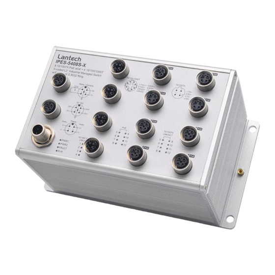
- Page 1 IPES-5408S-X Series 8 10/100TX D-coded + 4 10/100/1000T X-coded L2 w/8 PoE at/af Industrial Managed Switch w/Enhanced G.8032 Ring User Manual (Hardware) Dec. 2017...
- Page 2 Recommendation for Shielded network cables STP cables have additional shielding material that is used to reduce external interference. The shield also reduces the emission at any point in the path of the cable. Our recommendation is to deploy an STP network cable in demanding electrical environments. Examples of demanding indoor environments are where the network cable is located in parallel with electrical mains supply cables or where large inductive loads such as motors or contactors are in close vicinity to the camera or its cable.
- Page 3 Lantech Communications Global Inc. Products offered may contain software which is proprietary to Lantech Communications Global Inc. The offer or supply of these products and services does not include or infer any transfer of ownership.
- Page 4 FCC Warning This Equipment has been tested and found to comply with the limits for a Class-A digital device, pursuant to Part 15 of the FCC rules. These limits are designed to provide reasonable protection against harmful interference in a residential installation. This equipment generates, uses, and can radiate radio frequency energy.
-
Page 5: Table Of Contents
Content Chapter 1 Hardware Description......5 Physical Dimension ........5 Package Content: ......... 7 IP Protection ..........7 LED Indicators ..........10 Chapter 2 Hardware Installation ......12 Chapter 4 Network Application ......18 4.1 ITU G.8032 Scheme........18 4.2 Ring Coupling ..........18 4.3 Multiple Rings ..........19 4.4 Dual Homing ..........20 4.5 Chain ............20... -
Page 6: Chapter 1 Hardware Description
Chapter 1 Hardware Description In this paragraph, it will describe the Industrial switch’s hardware spec, port, cabling information, and wiring installation. 1.1 Physical Dimension Aluminum case. IP-65, 178mm(W)x99mm(H)x103mm(D) - Page 7 Port description of IP-65 series switch...
-
Page 8: Package Content
1.2 Package Content: Industrial Switch x1 Console cable x1 1.3 IP Protection The IP Code, Ingress Protection Rating, sometimes also interpreted as International Protection Rating, classifies and rates the degree of protection provided against the intrusion (including body parts such as hands and fingers), dust, accidental contact, and water in mechanical casings and with electrical enclosures. - Page 9 satisfactory operation of the equipment; complete protection against contact No ingress of dust; complete protection against Dust tight contact Liquid ingress protection The second digit indicates the level of protection that the enclosure provides against harmful ingress of water. Protected Level Testing for Details...
- Page 10 Water jets Water projected by a Test duration: at least nozzle (6.3 mm) against 15 minutes enclosure from any Water volume: 12.5 litres per direction shall have no minute harmful effects. Pressure: 30 kPa at distance of 3 m Powerful Water projected in powerful Test duration: at least water jets...
-
Page 11: Led Indicators
it produces no harmful effects. — Powerful Protected against close- high range high pressure, high temperature temperature spray downs. water jets 1.4 LED Indicators The diagnostic LEDs that provide real-time information of system and optional status are located on the front panel of the industrial switch. The following table provides the description of the LED status and their meanings for the switch. - Page 12 A network device is detected. The port is transmitting or receiving packets P1 ~ P4 Link/Ack Blinking from the TX device. No device attached...
-
Page 13: Chapter 2 Hardware Installation
Chapter 2 Hardware Installation 3.1Hardware installation 3.1.1Unpack switch and check the accessory with packing content list 3.1.2 Mount the switch on desired position. For the best ventilation, it is suggested to mount the switch on metallic surface. 3.1.3 Connect the M12 connector of power input. ... - Page 14 Pin assignment of Power input Dual Power Input The power input can be supported redundantly. The supply voltage is electrically isolated from the housing. Note: With single power supply of the mains voltage, the device will report a power failure. You can disable this power fail event via web browser.
- Page 15 Pin assignment of DI/DO 3.1.4 Fitting the device, grounding Install the system in a dry and clean area to protect the switch to get exposed with dirt. Plug the connector to the power supply plug then turn on the power supply.
- Page 16 Ground screw of IPES-5408S-X switch 3.1.5 Connect the M12 connector with RJ-45 data cable, ports are not used shall be caped that comes with the package to insulate the surrounding.
- Page 17 Pin assignment of M12 10/100Tx network connector Pin assignment of M12 10/100/1000T network connector...
- Page 18 3.1.6 Check the status of LED, make sure the switch was in working status. Note: The protection class IP65 is only achieved when bolted together. The other components attaching to the system have to meet with the IP65 protection class in order to reach the whole system IP65 protection. ...
-
Page 19: Chapter 4 Network Application
Chapter 4 Network Application 4.1 ITU G.8032 Scheme LANTECH G.8032 protocol is following ITU (International Telecommunication Unit) G.8032 v2 draft. The benefits of G.8032 are: 1. <50ms recovery time when failover 2. G.8032 has defined the protocol scheme, parameters, functions, test measures to be unified that the users can evaluate the possible network infrastructure without literally testing each brand in large scale. -
Page 20: Multiple Rings
4.3 Multiple Rings... -
Page 21: Dual Homing
4.4 Dual Homing 4.5 Chain... -
Page 23: Chapter 5 Console Management
Chapter 5 Console Management 5.1 Connecting to the Console Port The supplied cable which one end is M12 5-pole connector and the other end is RS-232 connector. Attach the end of RS-232 connector to PC or terminal and the other end of M12 connector to the console port of the switch. - Page 24 The settings of communication parameters Having finished the parameter settings, click ‘OK’. When the blank screen shows up, press Enter key to have the login prompt appears. Key in ‘admin’ (default value) for both User name and Password (use Enter key to switch), then press Enter and the Main Menu of console management appears.
Need help?
Do you have a question about the IPES-5408S-X Series and is the answer not in the manual?
Questions and answers