
Related Manuals for Lantech LPES-2224C


Summary of Contents for Lantech LPES-2224C
-
Page 1: User Manual
Lantech LPES-2224C 24 10/100TX + 2 10/100/1000T/ Mini-GBIC Combo Managed PoE Switch User Manual Rev.1.00 Jun-2009... - Page 2 Notice The contents of this manual are based on the table below listing firmware version, software kernel version, and hardware version. If the functions of the equipment are different from the manual, please contact the local sale dealer for more information. Firmware Version V1.00 Kernel Version...
-
Page 3: Fcc Warning
FCC Warning This Equipment has been tested and found to comply with the limits for a Class-A digital device, pursuant to Part 15 of the FCC rules. These limits are designed to provide reasonable protection against harmful interference in a residential installation. This equipment generates, uses, and can radiate radio frequency energy. -
Page 4: Table Of Contents
Contents FCC Warning ......................... i CE Mark Warning ......................i INTRODUCTION ......................1 Features ........................1 Software Features ......................2 Package Contents ......................5 HARDWARE DESCRIPTION ..................6 Physical Dimension ...................... 6 Front Panel ........................6 LED Indicators ......................7 Rear Panel ........................ - Page 5 QOS Commands Set ..............33 IGMP Commands Set ..............35 Mac / Filter Table Commands Set ..........36 SNMP Commands Set ..............38 Port Mirroring Commands Set ............39 802.1x Commands Set ..............40 ...
- Page 6 VLAN configuration ....................66 Port-based VLAN ..................66 802.1Q VLAN ....................69 Spanning Tree ..................... 74 System Configuration ................... 74 Per Port Configuration .................. 76 Port Mirroring ....................... 77 SNMP Management .................... 79 Security Manager ....................80 SNTP Configuration ..................... 81 802.1X Configuration ...................
- Page 7 Console Port Pin Assignments ................... 99 Cables ........................100 100BASE-TX/10BASE-T Pin Assignments ............... 100 2 Gigabit Copper/SFP (mini-GBIC) combo port: ............101...
-
Page 8: Introduction
Introduction The 24 10/100TX + 2 10/100/1000T/ Mini-GBIC Combo Managed PoE Switch is a multi-port Switch that can be used to build high-performance switched workgroup networks. This switch is a store-and-forward device that offers low latency for high-speed networking and allows the switch to auto-learn and store source address in an 8K-entry MAC address table. -
Page 9: Software Features
Supports IEEE 802.1p Class of Service Supports IEEE 802.1x User Authentication Supports Broadcast Storm Filter Supports DHCP Client Supports SNTP Supports System Event Log Management by Web/SNMP/Telnet/Console Software Features SNMP management Telnet management Management Web management RS-232 terminal console for command line interface management RFC 1157 SNMP RFC 1213 MIB II... - Page 10 RFC 2030 SNTP RFC Standard RFC 1215 Trap RFC 1757 RMON 1 TFTP Software Upgrade Console Support IEEE802.3ad with LACP function Up to 7 trunk groups and group members up to 4 Port Trunk The trunk port within 24-port 10/100TX and extension module IEEE802.1d Spanning Tree Spanning Tree...
- Page 11 Global system supports 3 mirroring types: RX, TX and Port Mirror Both packet The maximum of port mirror entries is up to 25 Per port supports bandwidth control Bandwidth Control Per level 100Kbps IEEE802.1x User-Authentication and can report to RADIUS server Reject 802.1x Authentication Accept...
-
Page 12: Package Contents
System detects status: I –sample Mode status V-sample R-detect SNTP RFC 2030 Simple Network Time Protocol System Log System Log record up to 1000 entries Power monitor Power supply monitoring function for AC power Power testing Supports power supply testing (CLI) Package Contents Unpack the contents of the 24 10/100TX + 2 10/100/1000T/ Mini-GBIC Combo Managed PoE Switch and verifies them against the checklist below:... -
Page 13: Hardware Description
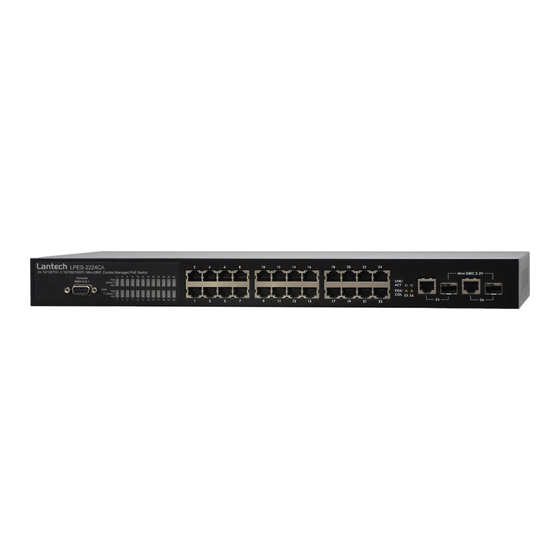
Hardware Description This chapter mainly describes the hardware of the 24 10/100TX + 2 10/100/1000T/ Mini-GBIC Combo Managed PoE Switch and gives a physical and functional overview on the certain switch. Physical Dimension The physical dimension of 24 10/100TX + 2 10/100/1000T/ Mini-GBIC Combo Managed PoE Switch is 440mmx 280mm x 44mm (W x D x H) Front Panel The front panel of the 24 10/100TX + 2 10/100/1000T/ Mini-GBIC Combo Managed... -
Page 14: Led Indicators
LED Indicators The LED indicators display a real-time indication of systematic operation status. There are three LED-Indicators (Link/Activity, Full duplex, PoE) for each UTP port and one power LED for the system unit. The following table provides descriptions of the LED statuses and meaning. -
Page 15: Rear Panel
In Half-duplex mode The PoE Injector function is on and power is Green forwarding the attached PD device The PoE injector function disables The port is connecting with the device and Green operating at speed of 1000Mbps The port is connecting with the device and Amber operating at speed of 100Mbps LNK/ACT (25 &... -
Page 16: Desktop Installation
below. The rear panel of the 24 10/100TX + 2 10/100/1000T/ Mini-GBIC Combo Managed PoE Switch Desktop Installation Set the switch on a sufficiently large flat space with a power outlet nearby. The surface where you put your switch should be clean, smooth, level and sturdy. Make sure there is enough clearance around the switch to allow attachment of cables, power cord and allow air circulation. -
Page 17: Power On
to the rack with a screwdriver and the rack-mounting screws. [Note] For proper ventilation, allow about at least 4 inches (10 cm) of clearance on the front and 3.4 inches (8 cm) on the back of the switch. This is especially important for enclosed rack installation. -
Page 18: Network Application
Network Application This section provides a few samples of network topology in which the switch is used. In general, the 24 10/100TX + 2 10/100/1000T/ Mini-GBIC Combo Managed PoE Switch with its large address table (8K MAC address) and high performance are ideal for interconnecting networking segments. -
Page 19: Segment Workgroup
Small Workgroup Application Segment workgroup For enterprise networks where large data broadcasts are constantly processed, this switch is an ideal solution for department users to connect to the corporate backbone. In the illustration below, two managed PoE switches with PCs, print server, local server, wireless AP (IEEE 802.3af compliant), and IP camera (IEEE 802.3af compliant) attached are both connect to the core switch. -
Page 20: Console Management
Console Management Connecting to the Switch The console port is a female DB-9 connector that enables a connection to a PC or terminal for monitoring and configuring the Switch. Use the supplied RS-232 cable with a male DB-9 connector to connect a terminal or PC to the Console port. The Console configuration (out of band) allows users to set switch for remote terminal as if the console terminal were directly connected to it. -
Page 21: Cli Management
the Main Menu of console management appears right after as below. The figure shown below is a login screen: Console login screen CLI Management The system supports console management—CLI command. After logging in to the system, a command prompt shows up. To enter CLI management interface, enter “enable”... - Page 22 • Perform basic tests. • Display system information. The privileged Enter the command is advance enable mode Privileged Enter disable command switch# Privileged this mode to to exit. EXEC while in user • Display advance EXEC mode. function status • Save configures Enter the To exit to configure...
-
Page 23: Commands Set List
Enter the PoE To exit to command Use this mode to PoE switch(PoE) privileged while in parameters for the EXEC mode, privileged switch. enter exit EXEC mode. Commands Set List System Commands Set Command Commands Description Defaults Example Level Global Switch (config)# system name Set switch system... - Page 24 Use the ip address interface configuration Switch (config)# ip address command to set an IP Global ip address [IP-address] address for a switch. configuration 192.168.1.1 [subnet-mask Use the no form of this mode 255.255.255.0 ] [ gateway] command to remove 192.168.1.254 an IP address or to disable IP processing.
- Page 25 Switch# show show Privileged Show username & accounting accounting EXEC password Username: root Password: root Switch> show system-info Name: switch1 location: lab show Show system User EXEC Description: system-info information layer2 switch Contact: somewhere Serial NO: 1.00 Switch# show ip address ip: 192.168.1.1 Privileged...
-
Page 26: Port Commands Set
Port Commands Set Command Commands Description Defaults Example Level Use the fast Ethernet Switch (config)# interface configuration interface interface command fastEthernet 0/1 [FastEthernet Interface configuration /module Use the module Switch (config)# Ethernet] [slot mode Ethernet interface interface id] [id] configuration moduleEthernet command Use the duplex... - Page 27 Use the speed configuration command to specify the speed mode of operation for module Switch (config)# Ethernet. Interface interface speed [10| 100 | The 100Base-FX configuration fastEthernet 1/2 1000 | auto] module only mode Switch (config-if)# supported for speed speed 1000 The 1000Base-FX module only supported for speed...
- Page 28 Use the priority configuration Switch (config)# priority on Interface command on Ethernet interface configuration ports. Disable [high | low] or fastEthernet 0/1 no priority mode Use the no form of this Switch (config-if)# command to disable priority on high security on the port. Set bandwidth in or out Switch (config)# rate.
- Page 29 Switch (config)# interface Interface show interface show interface fastEthernet 0/1 configuration configuration configuration status Switch (config-if)# mode show interface configuration Switch (config)# interface Interface show interface show interface actual fastEthernet 0/1 configuration status Switch (config-if)# status mode show interface status Switch (config)# interface Interface...
-
Page 30: Trunk Commands Set
Trunk Commands Set Command Commands Description Defaults Example Level Switch # show Display trunk group group 1 information. If there Group Trunk.1: Privileged show group is no group-number Ports: 02 03 04 [group-ID] EXEC mode in put, display all Priority: 0001 trunk groups. -
Page 31: Vlan Commands Set
VLAN Commands Set Command Commands Description Defaults Example Level To enter the VLAN Switch# vlan Privileged configuration Vlan datatbase database EXEC mode interface Switch(vlan)# To set switch vlanmode VLAN VLAN mode .Use [disable| Switch (vlan)# database the no form of this Disable portbase| vlanmode 802.1q... - Page 32 vlan [Group VLAN Remove the port Switch (vlan)# vlan name] delete database from it’s port group. v2 delete 5 [port ID] mode 802.1Q | 802.1Q with GVRP VLAN mode Add new 802.1Q vlan [Group VLAN name] VLAN [group name]: Switch(vlan)# vlan vlanid [group database VLAN name...
- Page 33 ID] tag [port Appletalk-app protocol v3 arp Appletalk_AARP-ap vlanid 2 port 5-8 p_arp tag 6,8 Novell_IPX-ipx Banyan_vines-bany Switch(vlan)# vlan an_c4 protocol v3 banyan Banyan_vines-bany vlanid 2 port 5-8 an_c5 tag 6,8 Banyan_vines-bany an_ad Decent_mop_01-de cent_01 Decent_mop_02-de cent_02 Decent_dpr-decent _dpr Decent_LAT-decen t_lat Decent_LAVC-dece nt_lavc...
- Page 34 [1280~1535] range [1536~1791] range [1792~2047] range [2048~2303] range [2304~2559] range [2560~2815] range [2816~3071] range [3072~3327] range [3328~3583] range [3584~3839] range [3840~4094] range VLAN protocol [Group name] VLAN Set the port of Switch (vlan)# vlan add [port ID] database some port group protocol v2 add 5 mode tagged or untagged...
-
Page 35: Spanning Tree Commands Set
Show VLAN of show vlan VLAN Group Name or Switch (vlan)# show [Group name] database VLAN ID [Group ID] or vlan v2 2 mode information show vlan vlanid: 1 ~ 4094 show protocol vlan VLAN Protocol show vlan Switch (vlan)# show database protocol vlan protocol... - Page 36 Priority: 32768 Max Age: 20 Hello Time: 2 Forward Delay: 15 Priority: 32768 Mac Address: 004063800030 Root_Path_Cost: 0 Root Port: we are root Max Age: 20 Hello Time: 2 Forward Delay: 15 Use the spanning-tree Switch (config)# spanning-tree global configuration spanning-tree on [on / off] Global...
- Page 37 Use the spanning-tree max-age global configuration Global command to Switch (config)# spanning-tree configuration change the priority. 32768 spanning-tree priority [number] mode priority 32767 Use the no form of this command to return to the default interval. Use the spanning-tree max-age global configuration command to change the interval...
- Page 38 command to return to the default interval. Use the spanning-tree hello-time global configuration command to specify spanning-tree Global the interval Switch (config)# configuration between hello 2 sec. hello-time spanning-tree [seconds] mode bridge protocol data hello-time 3 units (BPDUs). Use the no form of this command to return to the default interval.
- Page 39 Use the no form of this command to return to the default value. Use the spanning-tree forward-time global configuration command to set the forwarding-time for the specified spanning-tree instances. The Global Switch (config)# spanning-tree forwarding time forward-time configuration 15 sec. spanning-tree determines how [seconds]...
-
Page 40: Qos Commands Set
tie for position as the root switch. Use the no form of this command to return to the default value. QOS Commands Set Command Commands Description Defaults Example Level Enable/Disable Global broadcast storm Switch (config)# storm-control [5|10|15|20|25| configuration control. Use the no qos storm-control off (%)] or no mode... - Page 41 WRR: Switch (config)# qos queuepolicy wrr hi 7 low 1 [Policy]:fcfs: first in and first out First Come First wrr: weight round Served: Global queuepolicy robin Switch (config)# [Policy] hi configuration Hi 2 ahbl: all high before qos queuepolicy [number] low mode Low 1 low.
-
Page 42: Igmp Commands Set
Switch (config)# show qos show qos Global Show low priority low-priority-delay low-priority-del configuration delay board. -bound ay-bound mode Qos low priority delay bound: 1 Switch (config)# show qos show qos Global Show bridge delay bridge-delay-bou bridge-delay-b configuration bound ound mode bridge-delay-bound IGMP Commands Set Command... -
Page 43: Mac / Filter Table Commands Set
Mac / Filter Table Commands Set Command Commands Description Defaults Example Level Use the Switch (config)# mac-address-table mac-address-table aging-time global aging-time on configuration mac-address-ta command to set the ble aging-time Switch (config)# length of time that a [on | off] mac-address-table dynamic entry aging-time 333... - Page 44 Switch (config)# interface Use the no mac-address-ta fastEthernet 0/2 mac-address-table ble [static | Interface Switch (config-if)# privileged EXEC filter] hwaddr configuration command to delete [MAC address] mode mac-address-table entries from the MAC vlanid static hwaddr address table. [VLAN-ID] 004063112233 vlanid 10 Use the show show mac-address-table...
-
Page 45: Snmp Commands Set
SNMP Commands Set Command Commands Description Defaults Example Level snmp Global Switch (config)# Set SNMP agent system-name configuration snmp system-name system name [word] mode l2switch snmp Global Switch (config)# Set SNMP agent configuration system-location snmp system location [word] mode system-location lab Switch (config)# snmp Global... -
Page 46: Port Mirroring Commands Set
address] 192.168.1.50 community community public [word] Global Switch (config)# snmp Set SNMP agent system-name configuration snmp system-name system name [word] mode l2switch Port Mirroring Commands Set Command Commands Description Defaults Example Level Use the port monitor interface configuration command to port monitor enable Switch Switch (config)#... -
Page 47: 802.1X Commands Set
enabled. Port 05 TxRx: Port 06 TxRx: Port 07 TxRx: Port 08 TxRx: Analysis Port 09 TxRx: Port 10 TxRx: 802.1x Commands Set Command Commands Description Defaults Example Level Display a summary of User EXEC Switch> show the 802.1x properties show 8021x mode 8021x... - Page 48 Use the 802.1x system Switch (config)# 8021x system sharekey global 8021x system sharekey configuration command sharekey 123456 [number] Global to change the shared configuration key value. 123456 (Default) no 8021x mode Switch (config)# system Use the no form of this no 8021x system sharekey command to return to...
- Page 49 Use the 802.1x misc TX Switch (config)# period global 8021x misc 8021x misc configuration command txperiod 5 txperiod [sec.] Global to set the TX period. configuration 30 sec. (Default) no 8021x mode Use the no form of this Switch(config)# no txperiod command to return to 8021x misc...
-
Page 50: Tftp Commands Set
Reject: the specified accept port is required to be held in the unauthorized state. Accept: the specified port is required to be held in the Authorized state. Authorized: the specified port is set to the Authorized or Unauthorized state in accordance with the outcome of an authentication... -
Page 51: Poe Commands Set
Filename:backup.dat Switch(config)# tftp:config.text Tftp:config.text flash Global flash Restore configure [TFTP IP configuration Server file command address] [file mode IP:192.168.1.1 name] Image Filename:restore.dat Switch (config)# tftp:firmware Tftp:firmware flash flash Global Update firmware Server [TFTP IP configuration command IP:192.168.1.1 address] mode Image [file name] Filename:image.bin PoE Commands Set... - Page 52 Enabling or disabling total power output limit. When is enabling, the setlimit Switch(PoE)# PoE mode total power output limit [value] setlimit 100 will follow the value that set in power limit max. portebl Enabling or disabling Switch(PoE)# [enable | PoE mode the port PoE injected portebl disable disable]...
-
Page 53: System Log Commands Set
System log Commands Set Command Commands Description Defaults Example Level show Switch> User EXEC Display system log. systemlog show systemlog switch# show systemlog Syslog Client: show Privileged Show system log client Enable EXEC & server information systemlog Syslog Server Ip: 192.168.16.2 Global Switch(config)#... - Page 54 mode sntp Global Switch(config)# configuration Set time zone. timezone sntp timezone 8 [value] mode...
-
Page 55: Web-Based Management
Web-Based Management This section introduces the configuration and functions of the Web-Based management. About Web-based Management On the CPU board of the switch there is an embedded HTML web site residing in flash memory, which offers advanced management features and allow users to manage the switch from anywhere on the network through a standard browser such as Microsoft Internet Explorer. -
Page 56: Port Status
Uniform Resource Locator The login screen appears right after. Login screen Key in the user name and password. The default user name and password are the same as ‘root’ Press Enter or click OK button, and then the home screen of the Web-based management shows up. -
Page 57: View The Port Information
value was configured by the user. Actual means the current value of the port. Speed Duplex: Displays port connection speed. Config column means that its value was configured by the user. Actual means the current value of the port. Flow Control: Displays the Flow Control status in full mode. Config column means that its value was configured by the user. -
Page 58: Port Statistics
Click the port on the switch panel figure on the web page and a port information window will show up as below: Port information interface Port Statistics Display the current port statistic information Scroll down for more ports statistics Click Clear button to clean all counts... -
Page 59: Administrator
Port Statistics interface Administrator Administrator function provides the following functions—IP Configuration, Switch Settings, Console Port Information, Port Controls, Trunking, Forwarding and Filtering, VLAN Configuration, Spanning Tree, Port Mirroring, SNMP Management, Security Manager, 802.1x Configuration, and System Log. -
Page 60: Ip Address
IP Address Configure the IP address and DHCP client function. DHCP Client: Enable or disable the DHCP client function. When DHCP client function is enabled, the switch will be assigned an IP address from the network DHCP server. Moreover, the default IP address will be replaced by the assigned IP address on DHCP server. -
Page 61: Advanced
System Location: Displays the switch physical location. System Description: Displays the description of the switch. Firmware Version: Displays the Firmware version of the switch. Kernel Version: Displays the Kernel Software version. Hardware version: Displays the Hardware version of the switch. MAC Address: Displays the unique hardware address assigned by manufacturer (default). - Page 62 Enable Low Queue Delay Bound: Limit the low priority packets queuing time in the switch. If the low priority packet stays in switch exceeding Max Delay Time, it will be sent. The valid range is from 1 ~ 255 ms. [NOTE] Delay Bound must work under “Max bridge transit delay bound”...
-
Page 63: Misc Configuration
Priority Queue Service settings: Select the priority queue service type. 801.1p Priority First Come First Service: The sequence of packets sent depend on arriving order. All High before Low: The high priority packets sent before low priority packets Weighted Round Ratio: Select the preference given to packets in the switch's high-priority queue. -
Page 64: Console Port Information
Switch Misc Config setting interface Console Port Information Console is a standard UART interface to communicate with Serial Port. Use windows HyperTerminal program to link the switch. Please refer to Console Management Console login for detail steps. Console port information displays as follow: Bits per seconds: 9600 Data bits: 8 Parity: none... -
Page 65: Port Controls
Port Controls Change the port status Select the port by scroll the list in Port column State: Current port status. The port can be set to disable or enable mode. If the port state is set as ‘Disable’, it will not receive or transmit any packet. Negotiation: Auto and Force. -
Page 66: Trunking
addresses function to define a list of MAC addresses that can access to secure port. Click button to apply all configuration. Apply The port current configuration also will be displayed when the port is selected. Port Control interface Trunking The Link Aggregation Control Protocol (LACP) provides a standardized means for exchanging information between Partner Systems on a link to allow their Link Aggregation Control instances to reach agreement on the identity of the Link Aggregation Group to which the link belongs, move the link to that Link Aggregation... - Page 67 click Select button. LACP: When enabled, the trunk group is using LACP. A port which joins an LACP trunk group has to make an agreement with its member ports first. When disabled, the trunk group is a static trunk group. The advantage of having the LACP disabled is that a port joins the trunk group without any handshaking with its member ports.
-
Page 68: Aggregator Information
Trunking—Aggregator Setting interface Aggregator Information When you have setup the aggregator setting with LACP disabled, you will see the local static trunk group information in here. Group Key: Displays the trunk group ID. Port Member: Displays the members of this static trunk group. Trunking—Aggregator Information interface... -
Page 69: Aggregator State Activity
Aggregator State Activity Having set up the LACP aggregator on the tab of Aggregator Setting, you can configure the state activity for the members of the LACP trunk group. You can tick or cancel the checkbox beside the state display. When you remove the tick mark to the port and click Apply button, the port state activity will change to Passive. -
Page 70: Forwarding And Filtering
Forwarding and Filtering IGMP Snooping The Internet Group Management Protocol (IGMP) is an internal protocol of the Internet Protocol (IP) suite. IP manages multicast traffic by using switches, routers, and hosts that support IGMP. Enabling IGMP allows the ports to detect IGMP queries, report packets, and manage IP multicast traffic through the switch. -
Page 71: Static Mac Address
IGMP Snooping interface Static MAC Address When the user adds a static MAC address which will remains in the switch's address table, regardless of whether the device is physically connected to the switch. This saves the switch from having to re-learn a device's MAC address when the disconnected or powered-off device is active on the network again. - Page 72 Static MAC Address interface MAC filtering MAC address filtering allows the switch to drop unwanted traffic. Traffic is filtered based on the destination addresses. MAC Address: Enter the MAC address that you want to filter. VLAN ID: If tag-based (802.1Q) VLAN are set up on the switch, key in the VID in the VLAN ID field to associate with the MAC address.
-
Page 73: Vlan Configuration
MAC Filtering interface VLAN configuration A Virtual LAN (VLAN) is a logical network grouping that limits the broadcast domain, which would allow you to isolate network traffic, so only the members of the same VLAN will receive traffic from the ones of the same VLAN. Basically, creating a VLAN from a switch is logically equivalent of reconnecting a group of network devices to another Layer 2 switch. - Page 74 the VLAN-tagging is ignored. In order for an end station to send packets to different VLAN groups, it itself has to be either capable of tagging packets it sends with VLAN tags or attached to a VLAN-aware bridge that is capable of classifying and tagging the packet with different VLAN ID based on not only default PVID but also other information about the packet, such as the protocol.
- Page 75 VLAN—PortBase Add interface Key in the VLAN name, VLAN ID and select the members for the VLAN group. And then, click Apply...
-
Page 76: 802.1Q Vlan
The VLAN groups will be displayed in table To view the VLAN groups in next page, press to the next page Next Page To delete VLAN groups, press button Delete To modify VLAN groups, click Edit button [Note] If the trunk groups have been configured, the trunk groups will list in the port list (For example: Trunk1, Trunk2…). - Page 77 802.1q VLAN interface Click the hyperlink “Configuration” to enter the VLAN configuration interface. Enable GVRP Protocol: Ticked the check box to enable GVRP protocol. Enable security VLAN setting: Tick the check box to enable security VLAN group. When you select to enable security VLAN group, only the members in this VLAN group can access the switch.
- Page 78 802.1q VLAN –Add interface Group the ports, and then click button. If the trunk groups have been configured, the trunk groups will list in the port list (For example: Trunk1, Trunk2…). The trunk group also can be configured as the VLAN member.
- Page 79 And then, click Next will see the page as below:...
- Page 80 Set the outgoing frames as VLAN-Tagged frames or untagged. Tag: The outgoing frames involve VLAN tag. Untag: The outgoing frames don’t involve VLAN tag. And then, click Apply button. Port VID: Configure port VID. VLAN ID: Set the port VLAN ID that will be assigned to untagged traffic on a given port.
-
Page 81: Spanning Tree
802.1q VLAN – Port VLAN ID interface Spanning Tree The Spanning-Tree Protocol (STP) is a standardized method (IEEE 802.1d) for avoiding loops in switched networks. When STP enabled, to ensure that only one path at a time is active between any two nodes on the network. It’s recommended to enable STP on all switches to ensure only one active path on the network. - Page 82 Modifying STP state: RSTP Mode: Set RSTP mode as 802.1d or 802.1w. Priority (0-61440): The switch with the lowest value has the highest priority and is selected as the root. If the value is changed, the user must reboot the switch.
-
Page 83: Per Port Configuration
Per Port Configuration Configure path cost and priority of every port Select the port in Port column. Path Cost: The cost of the path to the other bridge from this transmitting bridge at the specified port. Enter a number 1 through 200,000,000. Priority: Decide which port should be blocked by priority in LAN. -
Page 84: Port Mirroring
SPT – Per Port Configuration interface Port Mirroring The Port mirroring is a method for monitor traffic in switched networks. Traffic through ports can be monitored by one specific port which means traffic goes in or out monitored (source) ports will be duplicated into mirroring (analysis) port. - Page 85 Prot Mirroring interface Port Mirroring State: Set mirroring mode—Disable, RX, TX, and Both. Analysis Port: Select one port to be the analysis port which can be used to see all monitored port traffic. User can connect mirror port to LAN analyzer or Netxray. Monitor Port: Tick the check box to monitor port traffic which will be copied to mirror (analysis) port (The maximum monitored ports are 25).
-
Page 86: Snmp Management
SNMP Management The SNMP is a Protocol that governs the transfer of information between management and agent. The switch supports SNMP V1. Define management stations as trap managers and to enter SNMP community strings. System Options: Assign the name, location, contact information of the switch. Name: Key in a name for the switch. -
Page 87: Security Manager
(Read only). RW: Enable requests accompanied by this string to display MIB-object information and to set MIB objects (Read/Write). And then, click button. Trap Manager A trap manager is a management station that receives traps. The management station then generates alerts based on the received traps. If no trap manager is defined, no traps are issued. -
Page 88: Sntp Configuration
SNTP Configuration Configure the SNTP (Simple Network Time Protocol) setting which SNTP allows the switch to synchronize switch clocks in the Internet. Use this page to Enable/Disable SNTP client; set SNTP server IP address, and UTC (Coordinated Universal Time) timezone. SNTP Client: Enable or disable SNTP function to get the time from the SNTP server. -
Page 89: Per Port Configuration
Radius Server IP: Set the Radius Server IP address. Server Port: Set the UDP destination port for authentication requests to the specified Radius Server. Accounting Port: Set the UDP destination port for accounting requests to the specified Radius Server. Shared Key: Set an encryption key for use during authentication sessions with the specified radius server. -
Page 90: Misc Configuration
And then, click Apply button. 802.1x Configuration—Per Port Configuration Misc Configuration Quiet Period: Set the period which the port doesn’t try to acquire a supplicant. TX Period: Set the period the port waits for retransmit next EAPOL PDU during an authentication session. -
Page 91: System Log
Max Requests: Set the number of authentication that must time-out before authentication fails and the authentication session ends. Reauth period: Set the period of time which clients connected must be re-authenticated. And then, click Apply 802.1x Configuration – Misc Configuration interface System Log Configure the system event mode to collect system log. -
Page 92: Save Configuration
After configuring, Click Apply System Log Interface Save Configuration Save the configuration to the flash memory when the configurations have been changed. If users want to keep their configuration after rebooting the switch, they must save the configuration. Otherwise, the new configuration will be lost when the switch restart or power off. -
Page 93: Tftp Update Firmware
Save Configuration Interface TFTP Update Firmware Use this page (TFTP—Trivial File Transfer Protocol) to configure to update the switch’s flash image bank. Place the updated image file on the TFTP server. TFTP Server IP Address: Key in TFTP server IP address. Firmware File Name: The name of firmware image. -
Page 94: Tftp Restore Configuration
TFTP Restore Configuration Restore the stored configuration file from TFTP server. Place the stored configuration file on the TFTP server. TFTP Server IP Address: Key in the TFTP server IP address. Restore File Name: Key in the correct restore file image name. And then, click Apply button. -
Page 95: Factory Default
TFTP Backup Configuration interface Factory Default Reset Switch to default configuration. Default IP address: 192.168.16.1 Default Gateway: 192.168.16.254 Subnet mask: 255.255.255.0 Click button to reset switch to default setting. Default Factory Default interface System Reboot Reboot the Switch in software reset. Click Reboot button to reboot the switch. -
Page 96: Poe Status
System Reboot interface PoE Status View PoE port information and set configuration to each port. Select the port and set configuration. And then, click Apply button. Press the Refresh button to refresh. PoE Status Interface Power Limit Management: Enable/disable the PoE power management... - Page 97 function. Firmware: Displays the system firmware version. Total Power Limit: Set limit value of the total provided power to the PDs. Total Power (W): Displays the total power of all the port that provided to PDs. Port: Select the port you want to configure. Enable: Enable or disable the port status.
- Page 98 Discovery R (ohms): Displays the resistance value. Port Current (mA): Displays the current value. Port Voltage (V): Displays the voltage value. Port Power (W): Displays the watt value. Class Current (mA): Displays current class. When the Bypass classification is enabled, the class value will not show in here. Determined Class: Displays power class.
-
Page 99: Troubleshooting
Troubleshooting This section is intended to help solve the most common problems on the 24 10/100TX + 2 10/100/1000T/ Mini-GBIC Combo Managed PoE Switch. Incorrect connections The switch port can automatically detect straight or crossover cable when the user links the switch with other Ethernet device. For the RJ-45 connector should use correct UTP or STP cable, 10/100Mbps ports use 2 pairs twisted cable. -
Page 100: Improper Network Topologies
Improper Network Topologies It is important to make sure that the network topology is valid. Common topology faults include excessive cable length and too many repeaters (hubs) between end nodes. In addition, the user should make sure that the network topology contains no data path loops. - Page 101 Signal / Name RX+ / VCC - RX- / VCC - TX+ / VCC + TX- / VCC + When the PD device pin out is in MDI mode without bridge circuit function, please use the crossover cable for power and data transmission. Please refer to the above table for the pin out transform.
- Page 102 (VCC-) 1 1 (VCC-) (VCC-) 2 2(VCC-) (VCC+) 3 3(VCC+) (VCC+) 6 6(VCC+) MDI-X MDI w/ bridge circuit...
-
Page 103: Technical Specification
Technical Specification This section provides the specifications of the 24 10/100TX + 2 10/100/1000T/ Mini-GBIC Combo Managed PoE Switch IEEE802.3 10BASE-T IEEE802.3u 100BASE-TX IEEE802.3z Gigabit Fiber IEEE802.3ab Gigabit 1000BASE-T IEEE802.3x Flow Control and Back pressure IEEE802.3ad Port trunk with LACP Standard IEEE802.1d Spanning tree protocol IIEEE802.1w Rapid spanning tree protocol... - Page 104 One RS-232 DB-9 female connector for switch RS-232 connector management Switch architecture Store and forward switch architecture. Back-plane Up to 8.8Gbps MAC address 8K MAC address table with Auto learning function Memory 3Mbits for packet buffer 512Kbytes x 2 Flash ROM System memory 8Mbytes x 1 Dimensions...
- Page 105 FCC Class A, CE Safety UL, cUL, CE/EN60950...
-
Page 106: Appendix
Appendix Console Port Pin Assignments The DB-9 serial port on the front panel is used to connect to the switch for out-of-band console configuration. The console configuration program can be accessed from a terminal or a PC running a terminal emulation program. The pin assignments used to connect to the serial port are provided in the following tables. -
Page 107: Cables
Cables The RJ-45 ports on the switch support automatic MDI/MDI-X operation, so you can use standard straight-through twisted-pair cables to connect to any other network device (PCs, servers, switches, routers, or hubs). Please refer to the following table for cable specifications. -
Page 108: Gigabit Copper/Sfp (Mini-Gbic) Combo Port
straight-through cables for all network connections to PCs or servers, or to other switches or hubs. In straight-through cable, pins 1, 2, 3, and 6, at one end of the cable, are connected straight through to pins 1, 2, 3 and 6 at the other end of the cable. The table below shows the 10BASE-T/ 100BASE-TX MDI and MDI-X port pin outs.
Need help?
Do you have a question about the LPES-2224C and is the answer not in the manual?
Questions and answers