
Related Manuals for Lantech IES-3208C


Summary of Contents for Lantech IES-3208C
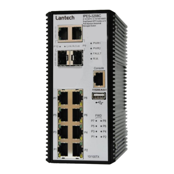
- Page 1 IES-3208C/3307C IPES-3208C/3307C IPES-3208CB/3307CB 8 (7)10/100Tx + 2(3) 10/100/1000T/Dual Speed SFP Combo and (8/7 PoE at/af) (Mode A/Mode B)Industrial Managed Switch w/ITU G.8032 Ring User Manual Mar. 2014...
-
Page 2: Important Notice
Lantech Communications Global Inc. Products offered may contain software which is proprietary to Lantech Communications Global Inc. The offer or supply of these products and services does not include or infer any transfer of ownership. -
Page 3: Fcc Warning
FCC Warning This Equipment has been tested and found to comply with the limits for a Class-A digital device, pursuant to Part 15 of the FCC rules. These limits are designed to provide reasonable protection against harmful interference in a residential installation. This equipment generates, uses, and can radiate radio frequency energy. -
Page 4: Table Of Contents
Content Chapter 1 Introduction ........... 1 Hardware Features ..........1 Software Features ..........3 Chapter 2 Hardware Description......8 Physical Dimension ........8 IP Protection ..........10 LED Indicators ..........13 Chapter 3 Hardware Installation ......14 3.1Hardware installation ........14 DIN-Rail Mounting ........15 Wall Mount Plate Mounting ......17 Wiring the Power Inputs .......18 Wiring the Fault Alarm Contact ....19... - Page 5 About Web-based Management ....29 Preparing for Web Management ....29 System Login ..........30 System ............31 6.4.1 System Identification Configuration ...... 31 6.4.2 Switch Information ..........32 6.4.3 IP configuration ............. 32 6.4.4 DHCP server ............34 6.4.5 System Time ........... 35 6.4.6 SNMP Configuration ..........
- Page 6 6.7.3 Detection ............... 61 6.7.4 Scheduling ............63 6.7.5 Configuration(PoE Mode B) ......... 64 6.7.6 Configuration(PoE Mode B) ......... 65 6.7.7 Detection(Mode B) ..........65 6.7.8 Scheduling(Mode B) ..........67 6.8 Topology ............68 6.9 QoS ..............71 6.9.1 QoS Policy ............71 6.10 Security ............73 6.10.1 MAC Address Tables ..........
- Page 7 6.14.2 IGMP Snooping Status ........92 6.15 MSTP ............94 6.15.1. MSTP Global Configuration .......94 6.15.2 How to enable MSTP .......... 95 6.15.3 CIST Settings............97 6.15.3.1 Bridge configuration ......97 6.15.3.2 Port ............ 97 6.15.4. MSTP MSTI Settings ......... 98 6.15.5.
-
Page 8: Chapter 1 Introduction
Cisco Discovery Protocol (CDP) and LLDP for Ciscoworks to detect the switch info to be shown on L2 map topology. The user friendly UI, innovative auto topology drawing and topology demo makes Lantech Full gigabit series much easier to get hands-on. - Page 9 14,880pps for Ethernet port Transfer Rate 148,800pps for Fast Ethernet port 1,488,000pps for Gigabit Ethernet port MAC Address 16K MAC address table 10/100Tx: 8(7) x RJ-45 type connector(2/3 will reserve for combo SFP port) Dual Speed SFP Combo: 2(3) x 1000 SFP Sockets Connector Power &...
-
Page 10: Software Features
Operating C ~ 60 Temperature C ~ 75 C(Wide Temp series) Storage C ~ 85 Temperature Metal case. IP-30, Case Dimension 74(W) x 114 (D) x 152 (H) mm Installation DIN rail and wall mount ear** FCC Class A, CE EN61000-4-2, CE EN61000-4-3, CE EN- 61000-4-4, CE EN61000-4-5, CE EN61000-4-6, CE EN61000-4-8, CE EN61000-4-11, CE EN61000-4-12, CE EN61000-6-2, CE EN61000-6-4... - Page 11 Support various ring/chain topologies Ring covers data & multicast* packets Auto topology drawing Topology demo User friendly UI Auto configuration for G.8032* LACP Port Trunk: 4 Trunk groups/Maximum 4 trunk Port Trunk with members LACP Load balancing through LACP to distribute load* Supports LLDP to allow switch to advise its identification LLDP and capability on the LAN...
- Page 12 256 Policy based Access Control List SSL/ SSH for Management TACACS+ for Authentication* SMTP/Text SMS Supports SMTP Server and 6 e-mail accounts for receiving event alert; can send SMS text alert via mobile Spanning Tree Supports IEEE802.1d Spanning Tree and IEEE802.1w Rapid Spanning Tree, IEEE802.1s Multiple Spanning Tree The quality of service determined by port, Tag and IPv4 Quality of Service...
- Page 13 types of packet. The packet filter rate can be set an accurate value through the pull-down menu for the ingress packet filter and the egress packet limit. Built-in Real Time Clock to keep track of time always Supports Flow Control for Full-duplex and Back Pressure Flow Control for Half-duplex System Log...
- Page 14 Each port allows an alphabetic string of 128-byte assigned ifAlias as its own unique name via the SNMP or CLI interface...
-
Page 15: Chapter 2 Hardware Description
Chapter 2 Hardware Description In this paragraph, it will describe the Industrial switch’s hardware spec, port, cabling information, and wiring installation. 2.1 Physical Dimension Metal case. IP-30, 74(W) x 105 (D) x 152 (H) mm... -
Page 17: Ip Protection
2.2 IP Protection The IP Code, Ingress Protection Rating, sometimes also interpreted as International Protection Rating, classifies and rates the degree of protection provided against the intrusion (including body parts such as hands and fingers), dust, accidental contact, and water in mechanical casings and with electrical enclosures. It is published by the International Electrotechnical Commission (IEC) Solid particle protection The first digit indicates the level of protection that the enclosure provides against access... - Page 18 Liquid ingress protection The second digit indicates the level of protection that the enclosure provides against harmful ingress of water. Protected Level Testing for Details against — — protected Dripping Dripping water (vertically Test duration: 10 minutes water falling drops) shall have no Water equivalent to 1 mm harmful effect.
- Page 19 water jets jets (12.5 mm nozzle) 3 minutes against the enclosure from Water volume: 100 litres per any direction shall have no minute harmful effects. Pressure: 100 kPa at distance of 3 m Immersion Ingress of water in harmful Test duration: 30 minutes up to 1 m quantity shall not be Immersion at depth of at...
-
Page 20: Led Indicators
2.3 LED Indicators The diagnostic LEDs that provide real-time information of system and optional status are located on the front panel of the industrial switch. The following table provides the description of the LED status and their meanings for the switch. Color Status Meaning... -
Page 21: Chapter 3 Hardware Installation
Chapter 3 Hardware Installation 3.1Hardware installation 1. Unpack the Industrial switch 2. Check if the DIN-Rail is screwed on the Industrial switch or not. If the DIN-Rail is not screwed on the Industrial switch, please refer to DIN-Rail Mounting section for DIN- Rail installation. -
Page 22: Din-Rail Mounting
3.2 DIN-Rail Mounting The DIN-Rail is screwed on the industrial switch when out of factory. If the DIN-Rail is not screwed on the industrial switch, please see the following pictures to screw the DIN- Rail on the switch. Follow the steps below to hang the industrial switch. - Page 23 First, insert the top of DIN-Rail into the track. Then, lightly push the DIN-Rail into the track. Check if the DIN-Rail is tightened on the track or not. To remove the industrial switch from the track, reverse above steps.
-
Page 24: Wall Mount Plate Mounting
3.3 Wall Mount Plate Mounting Follow the steps below to mount the industrial switch with wall mount plate. 1. Remove the DIN-Rail from the industrial switch; loose the screws to remove the DIN- Rail. 2. Place the wall mount plate on the rear panel of the industrial switch. 3. -
Page 25: Wiring The Power Inputs
3.4 Wiring the Power Inputs Please follow the steps below to insert the power wire. 1. Insert AC or DC power wires into the contacts 1 and 2 for power 1, or 5 and 6 for power. 2. Tighten the wire-clamp screws for preventing the wires from loosing. 3. -
Page 26: Wiring The Fault Alarm Contact
3.5 Wiring the Fault Alarm Contact The fault alarm contacts are in the middle of the terminal block connector as the picture shows below. Inserting the wires, the switch will detect the fault status of the power failure, or port link failure (available for managed model) and then forms an open circuit. The following illustration shows an application example for wiring the fault alarm contacts. -
Page 27: Cabling
3.6 Cabling Use four twisted-pair, Category 5e or above cabling for RJ-45 port connection. The cable between the switch and the link partner (switch, hub, workstation, etc.) must be less than 100 meters (328 ft.) long. Fiber segment using single-mode connector type must use9/125 µm single-mode fiber cable. - Page 28 Transceiver Inserted Second, insert the fiber cable of LC connector into the transceiver. LC connector to the transceiver...
- Page 29 To remove the LC connector from the transceiver, please follow the steps shown below: First, press the upper side of the LC connector to release from the transceiver and pull it out. Remove LC connector Second, push down the metal loop and pull the transceiver out by the plastic handle. Pull out from the transceiver...
-
Page 30: Chapter 4 Network Application
Chapter 4 Network Application ITU G.8032 Scheme Lantech G.8032 protocol is following ITU (International Telecommunication Unit) G.8032 v2 draft. The benefits of G.8032 are: 1. <50ms recovery time when failover 2. G.8032 has defined the protocol scheme, parameters, functions, test measures to be unified that the users can evaluate the possible network infrastructure without literally testing each brand in large scale. -
Page 31: Multiple Rings
Multiple Rings... -
Page 32: Dual Homing
Dual Homing Chain... -
Page 34: Chapter 5 Console Management
Chapter 5 Console Management 5.1 Connecting to the Console Port The supplied cable which one end is RS-232 connector and the other end is RJ-45 connector. Attach the end of RS-232 connector to PC or terminal and the other end of RJ-45 connector to the console port of the switch. -
Page 35: Login In The Console Interface
5.2 Login in the Console Interface When the connection between Switch and PC is ready, turn on the PC and run a terminal emulation program or Hyper Terminal and configure its communication parameters to match the following default characteristics of the console port: Baud Rate:115200 bps Data Bits: 8 Parity: none... -
Page 36: Chapter 6 Web-Based Management
Chapter 6 Web-Based Management This section introduces the configuration and functions of the Web-Based management. 6.1 About Web-based Management There is an embedded HTML web site residing in flash memory on CPU board of the switch, which offers advanced management features and allows users to manage the switch from anywhere on the network through a standard browser such as Microsoft Internet Explorer. -
Page 37: System Login
6.3 System Login Launch the Internet Explorer on the PC(the switch also support Mozila and Chrome browser). Key in “http:// “+” the IP address of the switch”, and then Press “Enter”. The login screen will appear right after Key in the user name and password. The default user name and password are the same as ‘admin’. -
Page 38: System
6.4 System 6.4.1 System Identification Configuration Name: An administratively assigned name for this managed switch. By convention, this is the node's fully-qualified domain name. A domain name is a text string drawn from the alphabet (A-Z), digits (0-9), minus sign (-). No space characters are permitted as part of a name. -
Page 39: Switch Information
6.4.2 Switch Information User can find the system name, description, location and contact personnel to identify the switch. The version table below is a read-only field to show the basic information of the switch. 6.4.3 IP configuration... - Page 40 The switch is a network device which needs to be assigned an IP address for being identified on the network. Users can select a methodof assigning IP address to the switch. DHCP Client: Enable or disable the DHCP client function. When DHCP client function is enabled, the switch will obtain an IP address from the network DHCP server automatically.
-
Page 41: Dhcp Server
6.4.4 DHCP server DHCP is the abbreviation of Dynamic Host Configuration Protocol that is a protocol for assigning dynamic IP addresses to devices on a network. With dynamic addressing, a device can have a different IP address every time it connects to the network. -
Page 42: System Time
address. IP Range(down): Type in an IP address. High IP address is the end of the dynamic IP range. For example, dynamic IP is in the range between 192.168.1.100 ~ 192.168.1.200. In contrast, 192.168.1.200 is the High IP address. ... - Page 43 in each participating subnet peer. Daylight saving time (DST) is the convention of advancing clocks so that afternoons have more daylight and mornings have less. Typically clocks are adjusted forward one hour near the start of spring and are adjusted backward in autumn. ...
- Page 44 Nome, Alaska -11 hours 1 am CET - Central European FWT - French Winter MET - Middle European +1 hour 1 pm MEWT - Middle European Winter SWT - Swedish Winter EET - Eastern +2 hours 2 pm European, USSR Zone 1 BT - Baghdad, USSR +3 hours 3 pm...
- Page 45 SNTP Client setting Time zone This filed is to select the Timezone which this switch is located Manual Synchronize the time with the desktop which connect with switch. SNTP : This is to enable/disable the SNTP service, enable the SNTP client is to use the service from SNTP server, the system time will follow the SNTP server, disable is to use local time without any SNTP server information, note that the network should be enabled to have system receive time information from SNTP server if...
-
Page 46: Snmp Configuration
6.4.6 SNMP Configuration Simple Network Management Protocol (SNMP) is the protocol developed to manage nodes (servers, workstations, routers, switches and hubs etc.) on an IP network. SNMP enables network administrators to manage network performance, find and solve network problems, and plan for network growth. Network management systems learn of problems by receiving traps or change notices from network devices implementing SNMP. -
Page 47: Fault Relay Configuration
A trap manager is a management station that receives the SNMP trap messages generated by the switch. If no trap manager is defined, no traps will be issued. To define a management station as a trap manager, assign an IP address, enterthe SNMP community strings, and select the SNMP trap version. - Page 48 check boxes of power 1/power 2 ticked, the FAULT LED indicator will then be possible to light up when any one of the power failures occurs. As for the Port Link Down/Broken detection, the FAULT LED indicator will light up when the port failure occurs;...
-
Page 49: Digital Input/Output
6.4.8 Digital Input/Output The IPES/IES Industrial Switch contains two digital outputs and two digital inputs. Outputs are open-collector transistor switches that may be controlled by the host computer. They provide control signals, which can be applied to heaters, pumps, and other electrical equipment. - Page 50 Digital Output Setting When DO0/DO1function is enabled; first Digital Output (DO0) and second Digital Output (DO1) will then be available respectively. Condition: Tick the check boxes to decide whether or not to send the events via digital output with the event about port fail or power fail or both. ...
-
Page 51: Event & Log
6.5 Event & Log 6.5.1 View Logs This will show you the log in local interface, you can press or F5 to refresh the web page and get the newest event log. -
Page 52: Events
6.5.2 Events 6.5.2.1 Environmental Monitoring Event You can set the trigger range of each event here, for example, if you set the blue bar in the range from 20V to 50V, when the voltage of power input is over 50VDC or lower than the 20VDC, it will trigger the event system. -
Page 53: Ddm Event
6.5.3 DDM event The switch supports DMI where can read all the parameters info from DDM SFP when plugged into SFP slots, the shown information is as above including SFP temperature, input voltage, TX bias, TX dBm and RX dBM. You can set the trigger range of each event here, for example, when you set the blue bar in the range from -45∘C to 90∘C, if the working Temp. -
Page 54: Actions
6.5.4 Actions 6.5.4.1 Local Log Action Save to Local: Save log to local file 6.5.4.2 Remote Syslog Action Log to Remote Syslog Server: Save log to Syslog Server... - Page 55 6.5.4.3 Email Action Email Alert: Sent log via Email 6.5.4.4 SMS Action SMS Alert: Sent log via SMS service. (The must connect with internet and define the SMS server before using this function)
- Page 56 (Currently the SMS service is offered by Lantech in Taiwan.) 6.5.4.5 SNMP Trap Action SNMP Trap Action: The setting page of this function will be redirect to SNMP TRAP. 6.5.3.6 DOut Action DOUT Action: The setting page of this function will be redirect to Digital...
-
Page 57: Event Action Map
6.5.5 Event Action Map 6.5.5.1Event Actions: A. Choose the event which you want to active B. You will find the event which you select will be display as below, then choose forwarding method to define how to forward this event to manager side. - Page 58 C. You can set the forwarding method of port break event in here.
-
Page 59: Ports
6.6 Ports 6.6.1 Device Settings In Port control you can configurethe settings of each port to control the connection parameters, and the status of each port is listed beneath. Port No.: The port number which you want to be configured. ... -
Page 60: Status
6.6.2 Status It will show you the status of port configuration setting. 6.6.3 Statistics The following chart provides the current statistic information which displays the real- time packet transfer status for each port. The user might use the information to plan and implement the network, or check and find the problem when the collision or heavy traffic occurs. -
Page 61: Mirroring
than 64 octets], oversize, CRC error, fragments and jabbers) via this port. Tx Abort Packet: The aborted packet while transmitting. Packet Collision: The counts of collision packet. Packet Dropped: The counts of dropped packet. Rx Bcast Packet: The counts of broadcast packet received. ... -
Page 62: Rate Limiting
6.6.5 Rate Limiting You can set up every port’s bandwidth rate and frame limitation type. All the ports support port egress rate control. For example, assume port 1 is 10Mbps, users can set it’s effective egress rate is 1Mbps, ingress rate is 500Kbps. -
Page 63: Loop Protection
6.6.6 Loop Protection The loop Protection is used to detect the presence of traffic. When switch receives packet’s (looping detection frame) MAC address the same as oneself from port, show Loop Protection happens. The port will be locked when it received the looping Protection frames. -
Page 64: Power Over Ethernet (Ipes Series)
6.7 Power over Ethernet (IPES series) This segment shows the PoE(Power over Ethernet) function complying with IEEE 802.3af/at standards, for the IPES-3208C/3307C switch, they only support PoE mode A, so there will display only Power of Ethernet in Web GUI, but for the IPES- 3208CB/3307CB switch, they support both the PoE Mode A and Mode B, so there will display Mode A and Mode B in Web GUI. -
Page 65: Configuration(Poe Mode A)
6.7.1 Configuration(PoE Mode A) Maximum Power Available: This function will limit the total power consumption and cannot exceed 250W. -
Page 66: Status
Port No. The number of each PoE port Enable Enable/disable the PoE function of each PoE port Scheduling This PoE port will be managed by scheduling function. Priority Set the priority of power supply, if the total power consumption of all PoE ports was over the value of maximum power available, the switch will offer the power to the high priority PoE port and stop to supply power to the low priority PoE port. - Page 67 Main Voltage: The input voltage for PoE power source Main Current The input current for PoE power source ---------------------------------------------------------------------------------------------------------------- Port No. The number of each PoE port. Link The connection status of each PoE port. State The PoE state of the end device.(Unknown means the end device is none-PD device) ...
-
Page 68: Detection
Note: 802.3af send 15.4W; receive 12.95W ~48VDC 802.3at send 30.0W; receive 25.50W ~54VDC 6.7.3 Detection The PoE detection function is to detect whether the connected PD is still alive by pinging the IP address. Should the PD is not responding, the switch can be set for consequence action such as rebooting PD etc. - Page 69 The number of PoE port Enabled Enable the PoE port with PoE detection function. IP address The IP address of the connected PD. Interval How frequent the switch will ping the IP address of PD. Retry Time How many times of ping failure the switch will define the PD as dead or failure.
-
Page 70: Scheduling
as followings: Nothing: No action Power Down: shutdown the power of the PoE port Power On: keep the power on with the PoE port Restart Forever: Restart the power of the PoE port always. Restart Once: only restart the PoE power one time. ... -
Page 71: Configuration(Poe Mode B)
6.7.5 Configuration(PoE Mode B) Port No. The number of each PoE port Enable Enable/disable the PoE function of each PoE port Scheduling This PoE port will be managed by scheduling function. -
Page 72: Configuration(Poe Mode B)
6.7.6 Configuration(PoE Mode B) Power Consumption: Total power consumption of all PoE ports Temperature Temperature of PoE chipset Current Output current of each PoE port Voltage Output Voltage of each PoE port Power Power consumption of each PoE port 6.7.7 Detection(Mode B) The PoE detection function is to detect whether the connected PD is still alive by pinging the IP address. - Page 73 The number of PoE port Enabled Enable the PoE port with PoE detection function. IP address The IP address of the connected PD. Interval How frequent the switch will ping the IP address of PD. Retry Time How many times of ping failure the switch will define the PD as dead or failure.
-
Page 74: Scheduling(Mode B)
as followings: Nothing: No action Power Down: shutdown the power of the PoE port Power On: keep the power on with the PoE port Restart Forever: Restart the power of the PoE port always. Restart Once: only restart the PoE power one time. ... -
Page 75: Topology
6.8 Topology This function can help user to build the network topology drawing automatically for the switches that are in closed looped and show the detail information of each switch node by clicking the icon. The topology view drawing can show the backup path with the dot line for overall picture, please remember to enable LLDP function before you use this function. - Page 76 Rings: show the information from ITU-Ring function Graphic View: Display each switch connection in the network by graphic. You can see the topology diagram which is assorted by the LLDP information. Physical : display the physical connection of network . ...
- Page 77 Demo: Demo display each topology in different connection.
-
Page 78: Qos
6.9 QoS Quality of Service (QoS) is the ability to provide different priority to different applications, users or data flows, or to guarantee a certain level of performance to a data flow. QoS guarantees are important if the network capacity is insufficient, especially for real-time streaming multimedia applications such as voice over IP or Video Teleconferencing, since these often require fixed bit rate and are delay sensitive, and in networks where the capacity is a limited resource, for example in... - Page 79 Port Base Priority Configure the priority level for each port. With the drop-down selection item of Priority Type above being selected as Port-based, this control item will then be available to set the queuing policy for each port. Set up the COS priority level.
-
Page 80: Security
6.10 Security 6.10.1 MAC Address Tables Use the MAC address table to ensure the port security. Static MAC Address You can add a static MAC address; it remains in the switch's address table, regardless of whether the device is physically connected to the switch. This saves the switch from having to re-learn a device's MAC address when the disconnected or powered-off device is active on the network again. -
Page 81: Access Control List
6.10.2 Access Control List The switch access control list (ACL) is probably the most commonly used object in the OSI layer 2 and 3. It is used for access filtering. The ACLs are divided into MAC and IP filtering. 6.10.2.1 ACL with Layer2 (MAC) ... -
Page 82: Ieee 802.1X Radius Server
6.10.3 IEEE 802.1X Radius Server 802.1X is an IEEE authentication specification which prevents the client from accessing a wireless access point or wired switch until it provides authority, like the user name and password that are verified by an authentication server (such as RADIUS server). -
Page 83: Ip Security
6.10.4 IP Security IP security function allows user to assign 20 specific IP addresses that have permission to access the switch through the web browser for the securing switch management. Enable IP Security When this option is in Enable mode, the Enable Web Server and Enable Telnet Server and Enable SSH Server check boxes will then be available. -
Page 84: Vlan
6.11 VLAN A Virtual LAN (VLAN) is a logical network grouping that limits the broadcast domain, which would allow you to isolate network traffic, so only the members of the same VLAN will receive traffic from the ones of the same VLAN. Basically, creating a VLAN on a switch is logically equivalent of reconnecting a group of network devices to another Layer 2 switch. - Page 85 Management VLAN ID: This will set which VLAN group can access the switch, the default “0” means all VLAN group, this limitation will not support port based VLAN. Link Type: There are 3 types of link type. 1. Access Link: A segment which provides the link path for one or more stations to the VLAN-aware device.
-
Page 86: Status
for the purpose of VLAN communication across switches. PVID This column field is available when Link Type is set as Access Link and Hybrid Link. Assign a number in the range between 1 and 4094. Tagged VID: This column field is available when Link Type is set as Trunk Link and Hybrid Link. Assign a number in the range between 1 and 4094. -
Page 87: Mvr
6.12 MVR The MVR feature enables multicast traffic forwarding on the Multicast VLAN. In a multicast television application, a PC or a television with a set-top box can receive the multicast stream. Multiple set-top boxes or PCs can be connected to one subscriber port, which is a switch port configured as an MVR receiver port. -
Page 88: Lldp
6.12 LLDP Link Layer Discovery Protocol (LLDP) is defined in the IEEE802.1AB, it is an emerging standard which provides a solution for the configuration issues caused by expanding LANs. LLDP specifically defines a standard method for Ethernetnetwork devices such as switches, routers and wireless LAN access points to advertise information about themselves to other nodes on the network and store the information they discover. -
Page 89: Lldp Neighbor
Enter characters to be id name for the logical LLDP port. Mode Select LLDP mode. Rx only The switch will not send out LLDP information, but LLDP information from neighbor units is analyzed. Tx only The switch will drop LLDP information received from neighbors, but will send out LLDP information. - Page 90 System Capabilities System Capabilities describes the neighbour unit's capabilities. The possible capabilities are: 1. Other 2. Repeater 3. Bridge 4. WLAN Access Point 5. Router 6. Telephone 7. DOCSIS cable device 8. Station only 9. Reserved When a capability is enabled, the capability is followed by (+). If the capability is disabled, the capability is followed by (-).
-
Page 91: Lldp Statistics
6.12.3 LLDP Statistics This page provides an overview of all LLDP traffic. Two types of counters are shown. Total are counters that refer to the whole stack, switch, while Port refer to per port counters for the currently selected switch. 6.12.3.1 Total ... - Page 92 Frames Received In Error The number of received LLDP frames containing some kind of error. Frames In The number of LLDP frames received on the port. Frames Out The number of LLDP frames transmitted on the port. ...
- Page 93 Frames Out The number of LLDP frames transmitted on the port. TLVs Discarded Each LLDP frame can contain multiple pieces of information, known as TLVs (TLV is short for "Type Length Value"). If a TLV is malformed, it is counted and discarded. ...
-
Page 94: Cdp
6.13 CDP The Cisco Discovery Protocol (CDP) is a proprietary data link layer protocol developed by Cisco. It is used to share information about other directly connected Cisco equipment, such as the OS version and IP address 6.13.1 CDP Configuration Device Settings ... -
Page 95: Cdp Port Configuration
6.13.2 CDP Port Configuration Port The switch port number of the logical CDP port. Enabled The switch will send out CDP information, and will analyze CDP information received from neighbors. 6.13.3. CDP Status Statistics Total Packets Output The number of CDP frames transmitted on the switch. - Page 96 Version Version is the CDP version advertised by the neighbor unit. Ageout TTL Ageout TTL is the ageout Time-To-Live advertised by the neighbor unit. Device ID The Device ID is the identification of the neighbor's CDP frames. Platform Platform is the description advertised by the neighbor unit. Software Version Software Version is the software version advertised by the neighbor unit.
-
Page 97: Igmp Snooping
6.14 IGMP Snooping The switch support IP multicast, you can enable IGMP protocol on web management’s switch setting configuration page, then the IGMP snooping information displays. IP multicast addresses range are from 224.0.0.0 through 239.255.255.255. -
Page 98: Igmp Snooping Configuration
6.14.1 IGMP Snooping Configuration 6.14.1.1 Global Configuration Enable Query: enable or disable the IGMP query function. The IGMP query information will be displayed in IGMP status section. Enable Snooping: enable or disable the IGMP protocol. Flood Well-known Multicasr traffic:let the switch know how to process the Multicast data stream which was unregistered with IGMP Query. -
Page 99: Igmp Snooping Status
6.14.2 IGMP Snooping Status 6.14.2.1 Statistics VLAN ID The VLAN ID of the entry. Status Querior Shows the Querior status is "ACTIVE" or "IDLE". "DISABLE" denotes the specific interface is administratively disabled. Queries Transmitted The number of Transmitted Queries. ... - Page 100 V3 Reports Received The number of Received V3 Reports. V2 Leaves Received The number of Received V2 Leaves. IGMP Groups Entries in the IGMP Group Table are shown on this page. VLAN ID VLAN ID of the group. ...
-
Page 101: Mstp
6.15 MSTP The section describes that how to configure the Spanning Tree Bridge and STP System settings. It allows you to configure STP System settings are used by all STP Bridge instance in the Switch. 6.15.1. MSTP Global Configuration Mode Show the STP protocol version setting. -
Page 102: How To Enable Mstp
Forward Delay The delay used by STP Bridges to transit Root and Designated Ports to Forwarding (used in STP compatible mode). Valid values are in the range 4 to 30 seconds. Max Age The maximum age of the information transmitted by the Bridge when it is the Root Bridge. - Page 103 6.15.2.3 Remember to press “Apply” 6.15.1.4 Save setting...
-
Page 104: Cist Settings
6.15.3 CIST Settings 6.15.3.1 Bridge configuration VLANs Mapped The list of VLANs mapped to the MSTI. The VLANs must be separated with comma and/or space. A VLAN can only be mapped to one MSTI. An unused MSTI should just be left empty. (I.e. not having any VLANs mapped to it.) Unmapped VLANs are mapped to the CIST. -
Page 105: Mstp Msti Settings
Control whether the oper Edge flag should start as being set or cleared. (The initial oper Edge state when a port is initialized). Control whether the bridge should enable automatic edge detection on the bridge port. This allows oper Edge to be derived from whether BPDU's are received on the port or not. -
Page 106: Mstp Bridges Status
6.15.5. MSTP Bridges Status Instance The Bridge Instance. ex: CIST, MSTI1, ... Bridge ID The Bridge ID of this Bridge instance. Root ID The Bridge ID of the currently elected root bridge. Root Port The switch port currently assigned the root port role. ... -
Page 107: Bridge Status Of All Ports
6.15.6. Bridge status of all ports Port The switch port number of the logical STP port. Role The current STP port role of the port. The port role can be one of the following values: AlternatePort BackupPort RootPort DesignatedPort Disabled. ... -
Page 108: Aggregation
6.16 Aggregation Port trunking is the combination of several ports or network cables to expand the connection speed beyond the limits of any one single port or network cable. Link Aggregation Control Protocol (LACP),which is a protocol running on layer 2, provides a standardized means in accordance with IEEE 802.3ad to bundle several physical ports together to form a single logical channel. -
Page 109: Lacp Port Status
are standby/redundant ports and can be aggregated if working ports fail. 6.16.2 LACP Port Status You can check the setting of Port aggregation in Status. Trunking Group Number of trunking group LACP Yes' means that LACP is enabled and the port link is up. 'No' means that LACP is not enabled or that the port link is down. -
Page 111: Erps
6.17 G.8032 ERPS ERPS specifies protection switching mechanisms and a protocol for Ethernet layer network rings. Ethernet Rings can provide wide-area multipoint connectivity more economically due to their reduced number of links. The mechanisms and protocol defined in this recommendation achieve highly reliable and stable protection and never form loops, which would fatally affect network operation and service availability. -
Page 112: Ethernet Ring Protection Configuration105
6.17.1. G.8032 Ethernet Ring Protection Configuration The G.8032 Ethernet Ring Protection Switch instances are configured here. The ID of the created Protection group Enabled Enable/Disable the G.8032 ERP. Role It can be either RPL owner or RPL Neighbor. ... -
Page 113: How To Set Erps G.8032
6.17.2 How to set ERPS G.8032 Make sure you have disabled the MSTP/RSTP protocol. Press “+” icon to add one ring with G.8032 protocol. PS: in this case, we will use the port9 and port10 of each switch to build a ring. ... - Page 114 switch. After enabling the ring of G8032, the port0 of owner switch will be blocked at first. To be safe, we suggest to finish all the settings of G8032 before connecting physically if the user is not familiar with the ring G8032 function. ...
-
Page 115: Dual Homing
The setting of none switch 6.18 Dual Homing... - Page 116 This function was designed to connect ITU-Ring with the other 3 party switches while maintaining redundant path. ID: the ID of Dual Homing connection Enable: enable the Dual Homing function of this port Role:...
-
Page 117: Maintenance
there should be 2 connections between RSTP with ITU-Ring, one set Primary, the other set Secondary Port: The port which connect to the switch which running RSTP protocol. 6.19 Maintenance 6.19.1 Save Configuration Save setting of switch 6.19.2 Config backup/restore ... -
Page 118: Restart Device
Reset to default You can reset the configuration of the switch on this page. Only the IP configuration is retained. The new configuration is available immediately, which means that no tart is necessary. 6.19.3 Restart device Reboot the switch with selected firmware. -
Page 119: Firmware Upgrade
6.19.4 Firmware Upgrade Update the switch with the firmware file which on your desktop. 6.19.5 Diagnostics PING Address: Set the IP address which you want to ping Count: Set the times of Ping Packet Size: set the size of Ping packet. - Page 120 ARP Table You can find the MAC address of each IP you have ping via this switch in here. DDM You can monitor the status of SFP module via DDM function. Note: Only the SFP module which support DDM spe. can offer the DDM information via switch.
- Page 121 Hide Thresholds: hide the thresholds information and only display the status information Event setup: will be redirected to DDM event, please reference to page47...
-
Page 123: Appendix -Command Line Mode
Appendix —Command Line mode Except the web access mode, the Lantech switch also support Telnet access and console access mode, to compare the web access mode, both the Telnet and console only support command line user interface, all these commands are shown as below: 1. - Page 124 Enter and the Main Menu of console management appears. Please see below figure for login screen. Notice: if you forgot the password, you can access the switch via console port and input lantech /lantech to restore the password to default.
- Page 125 2. Access via Telnet Use Telnet utility to access switch IP and make sure the socket was set as 23, all the commands under Telnet mode were the same as the Console mode. 3. Commands 3.1 System Command: system Parameter: N/A Description: Enter the system mode Example:...
- Page 126 3.1.1 Command: system> configuration Parameter: N/A Description: show the information of switch Example:...
- Page 127 3.1.2 Command: system > Contact Parameter: N/A Description: display or fix the contact information Example: if I want to change the contact windows to jacky@lantechcom.tw 3.1.3 Command: system > name Parameter: N/A Description: display or fix the system name Example: 3.1.4 Command: system >...
- Page 128 3.1.6 Command: system > DHCPclient Parameter: enable/disable Description: enable or disable DHCP client Example: 3.1.7 Command: system > DHCP server Parameter: [enable|disable] enable or disable DHCP server [<range_low>]/[<range_high>] set the IP range [<netmask>] set submask [<gateway>] set gateway [<dns>] set DNS server [<lease_time>]...
- Page 129 3.1.9 Command: system > netstatus Parameter: N/A Description: show the status about IP address Example: 3.1.10 Command: system > netsettingIPv4 Parameter: [<IpAddr>] set IP address [<netmask>] set netmask [<gatewayip>] set gateway [<dnsip>] set DNS server Description: set the IP detail of switch Example: 3.1.11 Command: system >...
- Page 130 3.1.12 Command: system > reboot Parameter: N/A Description: reboot the switch Example: 3.1.13 Command: system > restoredefault Parameter: keep_none restore all setting keep_all restore all but keep original IP address and account keep_ip restore all but keep original IP address keep_account ...
- Page 131 3.1.16 Command: system > ping Parameter; N/A Description: ping the IP address Example: 3.1.17 Command: system > arp Parameter: N/A Description: resolve the IP address to MAC address Example: 3.1.18 Command: system > memory Parameter: N/A Description: display the status of used switch memory Example: 3.1.19 Command: system >...
- Page 132 3.1.20 Command: system > upgrade Parameter: [URL] set the source of firmware file, support TFTP and FTP and HTTP protocol. Description: update switch firmware Example: 3.2 LLDP Command: LLDP Parameter: N/A Description: Enter the LLDP mode Example: 3.2.1 Command: LLDP > configuration Parameter: N/A Description: display the LLDP information Example:...
- Page 133 3.2.2 Command: LLDP > enabled Parameter: N/A Description: enable LLDP protocol Example: 3.2.3 Command: LLDP > mode Parameter: [<port_list>]display LLDP information of the dedicated port [enabledRxTx] enable Tx and Rx of LLDP function with dedicated port [enabledTxOnly] enable Tx only of LLDP function with dedicated port [enabledRxOnly]...
- Page 134 3.2.4 Command: LLDP > interval Parameter: N/A Description: set the interval time of LLDP Example: 3.2.5 Command: LLDP > timetolive Parameter: N/A Description: display the alive time of LLDP information. Example: 3.2.6 Command: LLDP > info Parameter: N/A Description: display the LLDP information of neighbor port Example:...
- Page 135 3.2.7 Command: LLDP > statistics Parameter: N/A Description: display the detail information of LLDP settings Example: 3.3 Port Command: port Parameter: N/A Description: Enter the port mode Example:...
- Page 136 3.3.1 Command: port > configuration Parameter: N/A Description: display the setting of each port Example: 3.3.2 Command: port > status Parameter: N/A Description: display the connection status of each port Example:...
- Page 137 3.3.3 Command: port > enabled Parameter: [<port_list>] choose which port you want to enable or diasble [enable|disable] enable/disable Description: enable or disable switch port Example: 3.3.4 Command: port > description Parameter: N/A Description: display the description of each port Example:...
- Page 138 3.3.5 Command: port > speed Parameter: N/A Description: display the speed of each port Example: 3.3.6 Command: port > flowcontrol Parameter: [<port_list>] choose which port you want to enable or diasble [enable|disable] enable/disable Description: enable or disable flow control function of each port Example:...
- Page 139 3.3.7 Command: port > Ingressrate Parameter: [<port_list>] choose which port you want to set the ingress rate [<rate> kbps]set the ingress rate of these packet as below broadcast multicast unicast broad_uni broad_multi multi_uni uni_broad_multi Description: set the ingress rate of the dedicated port with specified packet Example:...
- Page 140 3.3.8 Command: port > egressrate Parameter: [<port_list>] choose which port you want to set the ingress rate [<rate> kbps]set the ingress rate Description: set the egress rate of the dedicated port Example: 3.3.9 Command: port > statistics Parameter: N/A Description: display the detail information of port statistics Example:...
Need help?
Do you have a question about the IES-3208C and is the answer not in the manual?
Questions and answers