
Related Manuals for Lantech IGS-L5408MGSFPR-AC


Summary of Contents for Lantech IGS-L5408MGSFPR-AC
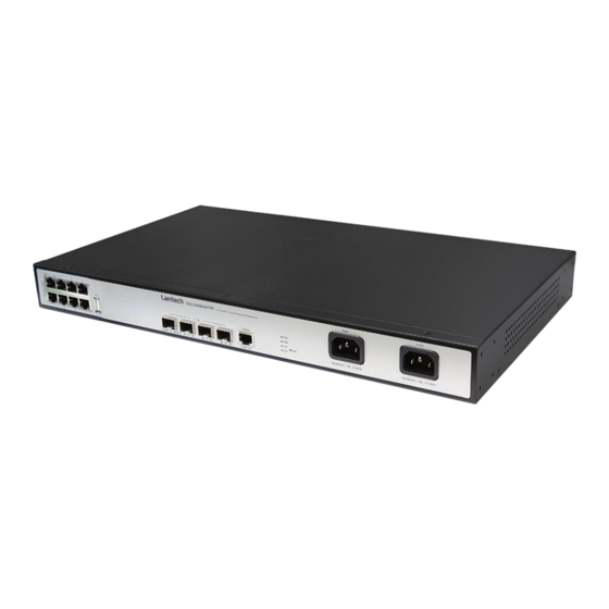
- Page 1 IGS-L5408MGSFPR-AC IGS-L5408MGSFPR-DC 8 10/100/1000T + 4 1G/2.5G SFP OS3 Industrial Managed Ethernet Switch User Manual (Hardware) Mar. 2022...
- Page 2 Recommendation for Shielded network cables STP cables have additional shielding material that is used to reduce external interference. The shield also reduces the emission at any point in the path of the cable. Our recommendation is to deploy an STP network cable in demanding electrical environments. Examples of demanding indoor environments are where the network cable is located in parallel with electrical mains supply cables or where large inductive loads such as motors or contactors are in close vicinity to the camera or its cable.
- Page 3 Lantech Communications Global Inc. Products offered may contain software which is proprietary to Lantech Communications Global Inc. The offer or supply of these products and services does not include or infer any transfer of ownership.
- Page 4 FCC Warning This Equipment has been tested and found to comply with the limits for a Class-A digital device, pursuant to Part 15 of the FCC rules. These limits are designed to provide reasonable protection against harmful interference in a residential installation. This equipment generates, uses, and can radiate radio frequency energy.
-
Page 5: Table Of Contents
Content Chapter 1 Introduction ..........5 Chapter 2 Hardware Description ......5 Physical Dimension ........5 IP Protection ........... 7 LED Indicators..........10 Chapter 3 Hardware Installation ......11 3.1. Rack Mounting ..........12 3.2. Wiring the Power Inputs ....... 14 3.3. -
Page 6: Chapter 1 Introduction
Chapter 1 Introduction Lantech IGS-L5408MGSFPR is a high performance OS3 Industrial Ethernet switch with 8 10/100/1000T + 4 1G/2.5G SFP which provides advanced security function for network aggregation deployment. Chapter 2 Hardware Description In this paragraph, it will describe the Industrial switch’s hardware spec, port, cabling information, and wiring installation. - Page 7 DC model Metal case. IP-30, 440mm(W)x255mm(D)x44mm(H)
-
Page 8: Ip Protection
2.2 IP Protection The IP Code, Ingress Protection Rating, sometimes also interpreted as International Protection Rating, classifies and rates the degree of protection provided against the intrusion (including body parts such as hands and fingers), dust, accidental contact, and water in mechanical casings and with electrical enclosures. It is published by the International Electrotechnical Commission (IEC) Solid particle protection The first digit indicates the level of protection that the enclosure provides against access... - Page 9 Liquid ingress protection The second digit indicates the level of protection that the enclosure provides against harmful ingress of water. Protected Level Testing for Details against — — protected Dripping Dripping water (vertically Test duration: 10 minutes water falling drops) shall have no Water equivalent to 1 mm harmful effect.
- Page 10 water jets jets (12.5 mm nozzle) 3 minutes against the enclosure from Water volume: 100 litres per any direction shall have no minute harmful effects. Pressure: 100 kPa at distance of 3 m Immersion Ingress of water in harmful Test duration: 30 minutes up to 1 m quantity shall not be Immersion at depth of at...
-
Page 11: Led Indicators
2.3 LED Indicators The diagnostic LEDs that provide real-time information of system and optional status are located on the front panel of the industrial switch. The following table provides the description of the LED status and their meanings for the switch. Color Status Meaning... -
Page 12: Chapter 3 Hardware Installation
For POE models: It is not advisable to use POE ports to uplink to another Unit. (May Cause Damage) Lantech strongly advise the installation of a Galvanic isolated DC/DC converter between the power supply and the Ethernet switch on all Non-Isolated units. -
Page 13: Rack Mounting
3.1. Rack Mounting When installing the IGS-L5408MGSFP switch in a 19 inch rack, it must always be mounted horizontally with the top side up. This procedure requires the following items: ■ Four bracket screws (included eight with the switch) ■ Two equipment rack brackets (included four with the switch) ■... -
Page 15: Wiring The Power Inputs
3.2. Wiring the Power Inputs Please follow the steps below to insert the power wire. AC model Connect the power cords to the connectors on the Ethernet switch and to the appropriate power sources. DC model 1. Insert DC power wires into the contacts + and – of the terminal block connector. 2. -
Page 16: Cabling
3.3. Cabling Use four twisted-pair, Category 5e or above cabling for RJ-45 port connection. The cable between the switch and the link partner (switch, hub, workstation, etc.) must be less than 100 meters (328 ft.) long. Fiber segment using single-mode connector type must use9/125 µm single-mode fiber cable. - Page 17 Transceiver Inserted Second, insert the fiber cable of LC connector into the transceiver. LC connector to the transceiver...
- Page 18 To remove the LC connector from the transceiver, please follow the steps shown below: First, press the upper side of the LC connector to release from the transceiver and pull it out. Remove LC connector Second, push down the metal loop and pull the transceiver out by the plastic handle. Pull out from the transceiver...
-
Page 19: Usb Dongle
3.4. USB Dongle The USB slot is to backup and restore the setting of switch automatically by any USB dongle. It doesn’t need any configuration from web browser or other user interface. When you plug USB dongle in switch , the switch will backup its configuration file automatically, the backup file will be named cfgexport_(switch MAC).yml, if you want to restore the backup file , just rename the configuration file as cfgimport_(switch MAC).yml then plug the USB dongle again. -
Page 20: Chapter 4 Console Management
Chapter 4 Console Management 4.1. Connecting to the Console Port The supplied cable which one end is RS-232 connector and the other end is RJ-45 connector. Attach the end of RS-232 connector to PC or terminal and the other end of RJ-45 connector to the console port of the switch. -
Page 21: Login In The Console Interface
4.2. Login in the Console Interface When the connection between Switch and PC is ready, turn on the PC and run a terminal emulation program or Hyper Terminal and configure its communication parameters to match the following default characteristics of the console port: Baud Rate:115200 bps Data Bits: 8 Parity: none... - Page 22 Console login interface...
-
Page 23: Chapter 5 Out-Of-Band Management
Chapter 5 Out-of-Band Management 5.1. Connecting to the OOB Port Connect an Ethernet cable from an Ethernet port on your server/computer to the OOB port on the switch. RJ-45 Connector RJ-45 Connector No Signal No Signal No Signal No Signal No Signal No Signal No Signal... - Page 24 ===============Notice=============== For web-based management, please refer to our “Software Management Manual”. Please contact support@lantechcom.tw for more information.
Need help?
Do you have a question about the IGS-L5408MGSFPR-AC and is the answer not in the manual?
Questions and answers