Table of Contents
Advertisement
FCC Warning
This Equipment has been tested and found to comply with the limits for a
Class-A digital device, pursuant to Part 15 of the FCC rules. These limits
are designed to provide reasonable protection against harmful interference
in a residential installation. This equipment generates, uses, and can
radiate radio frequency energy. It may cause harmful interference to radio
communications if the equipment is not installed and used in accordance
with the instructions. However, there is no guarantee that interference will
not occur in a particular installation. If this equipment does cause harmful
interference to radio or television reception, which can be determined by
turning the equipment off and on, the user is encouraged to try to correct
the interference by one or more of the following measures:
Reorient or relocate the receiving antenna.
Increase the separation between the equipment and receiver.
Connect the equipment into an outlet on a circuit different from that to
which the receiver is connected.
Consult the dealer or an experienced radio/TV technician for help.
CE Mark Warning
This is a Class-A product. In a domestic environment this product may
cause radio interference in which case the user may be required to take
adequate measures.
Chapter 1 Introduction
The IPES-3408 series Managed Industrial Switch is a cost-effective solution and meets
the high reliability requirements demanded by industrial applications. Using fiber port can
extend the connection distance that increases the network elasticity and performance.
1.1 Hardware Features
IEEE 802.3 10Base-T Ethernet
IEEE 802.3u 100Base-TX
IEEE802.3z Gigabit fiber
IEEE802.3x Flow Control and Back Pressure
IEEE802.3ad Port trunk with LACP
IEEE802.1d Spanning Tree
IEEE802.1w Rapid Spanning Tree
Standard
IEEE802.1s Multiple Spanning Tree
IEEE 802.3ad Link Aggregation Control Protocol (LACP)
IEEE 802.1AB Link Layer Discovery Protocol (LLDP)
IEEE 802.1X User Authentication (Radius)
IEEE802.1p Class of Service
IEEE802.1Q VLAN Tag
IEEE802.3at/af Power over Ethernet
IEEE 802.3az Efficient Energy Ethernet
Back-plane (Switching Fabric): 9.6Gbps
Switch
Packet throughput ability (Full-Duplex): 23.8Mpps
Architecture
@64bytes
14,880pps for Ethernet port
Transfer Rate
148,800pps for Fast Ethernet port
1,488,000pps for Gigabit Fiber Ethernet port
MAC Address
16K MAC address table
1
Advertisement
Table of Contents

Related Manuals for Lantech IPES-3408 Series


Summary of Contents for Lantech IPES-3408 Series
-
Page 1: Chapter 1 Introduction
Chapter 1 Introduction This Equipment has been tested and found to comply with the limits for a The IPES-3408 series Managed Industrial Switch is a cost-effective solution and meets Class-A digital device, pursuant to Part 15 of the FCC rules. These limits the high reliability requirements demanded by industrial applications. - Page 2 10/100TX: 8 x RJ-45 type connector IEC60068-2-32 (Free fall), IEC60068-2-27 (Shock), Stability Testing Mini-GBIC: 4 x 1000 SFP Sockets IEC60068-2-6 (Vibration) Connector Power & P-Fail connector: 1 x 6-pole terminal block RS-232 connector: 1 x RJ-45 type connector 10Base-T: 2-pair UTP/STP Cat. 3, 4, 5 cable EIA/TIA-568 100-ohm (100m) Network Cable 100Base-TX: 2-pair UTP/STP Cat.
-
Page 3: Software Features
1.2 Software Features Cisco Discovery Protocol for topology mapping PoE Detection to check if PD is hang up then restart Management SNMP v1 v2c, v3/ Web/Telnet/CLI Management the PD PoE Scheduling to On/OFF PD upon routine time RFC 1215 Traps MIB, table RFC 1213 MIBII, RFC 1157 SNMP MIB,... - Page 4 TACACS+ for Authentication* the pull-down menu for the ingress packet filter and the egress packet limit. SMTP/Text SMS Supports SMTP Server and 6 e-mail accounts for Built-in Real Time Clock to keep track of time always receiving event alert; can send SMS text alert via mobile Spanning Tree Supports IEEE802.1d Spanning Tree and IEEE802.1w Supports Flow Control for Full-duplex and Back Pressure...
-
Page 5: Chapter 2 Hardware Description
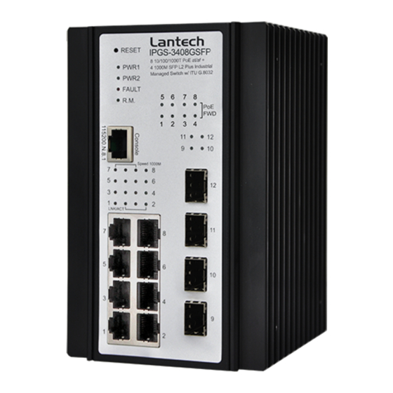
Chapter 2 Hardware Description Each port allows an alphabetic string of 128-byte assigned ifAlias as its own unique name via the SNMP or CLI interface information, and wiring installation. 2.1 Physical Dimension 65 (W) x 105 (D) x 152 (H) mm 2.2 Front Panel Front Panel of the industrial switch... -
Page 6: Top View
2.3 Top View 2.4 LED Indicators The top panel of the Industrial Managed Industrial Switch has one terminal block The diagnostic LEDs that provide real-time information of system and optional status are connector of two DC power inputs and one fault alarm. located on the front panel of the industrial switch. -
Page 7: Chapter 3 Hardware Installation
The DIN-Rail is screwed on the industrial switch when out of factory. If the DIN-Rail is In this paragraph, we will describe how to install the IPES-3408 series Managed not screwed on the industrial switch, please see the following pictures to screw the DIN- Industrial Switch and the installation points attended to it. -
Page 8: Wall Mount Plate Mounting
First, insert the top of DIN-Rail into the track. 3.3 Wall Mount Plate Mounting Follow the steps below to mount the industrial switch with wall mount plate. 1. Remove the DIN-Rail from the industrial switch; loose the screws to remove the DIN- Rail. -
Page 9: Wiring The Power Inputs
3.4 Wiring the Power Inputs 3.5 Wiring the Fault Alarm Contact Please follow the steps below to insert the power wire. The fault alarm contacts are in the middle of the terminal block connector as the picture shows below. Inserting the wires, the switch will detect the fault status of the power failure, or port link failure (available for managed model) and then forms an open circuit. - Page 10 3.6 Cabling To connect the transceiver and LC cable, please follow the steps shown below: Use four twisted-pair, Category 5e or above cabling for RJ-45 port connection. The First, insert the transceiver into the SFP module. Notice that the triangle mark is the cable between the switch and the link partner (switch, hub, workstation, etc.) must bottom of the module.
- Page 11 To remove the LC connector from the transceiver, please follow the steps shown below: First, press the upper side of the LC connector to release from the transceiver and pull it out. LC connector to the transceiver Remove LC connector Second, push down the metal loop and pull the transceiver out by the plastic handle.
-
Page 12: Chapter 4 Network Application
Chapter 4 Network Application 4.1 ITU G.8032 Scheme Lantech G.8032 protocol is following ITU (International Telecommunication Unit) G.8032 This chapter provides some sample applications to help user to have more actual idea of v2 draft. The benefits of G.8032 are: industrial switch function application. - Page 13 2-1. Dual Rings 4-1. Single Chain 2-2. Multiple Rings 4-2. Multiple Chains 4-3. Multiple Chains Share Common Ends 4-4. Cascade Chain...
-
Page 14: Chapter 5 Console Management
Chapter 5 Console Management 5.1 Connecting to the Console Port 4-5. Chain in Chain The supplied cable which one end is RS-232 connector and the other end is RJ-45 connector. Attach the end of RS-232 connector to PC or terminal and the other end of RJ-45 connector to the console port of the switch. -
Page 15: Login In The Console Interface
5.3 Login in the Console Interface Chapter 6 Web-Based Management When the connection between Switch and PC is ready, turn on the PC and run a terminal emulation program or Hyper Terminal and configure its communication This section introduces the configuration and functions of the Web-Based parameters to match the following default characteristics of the console port: management. -
Page 16: System Login
6.3 System Login 6.4 System Launch the Internet Explorer on the PC 6.4.1 System Identification Configuration Enter Name: An administratively assigned name for this managed node. By convention, this is the node's fully-qualified domain name. A domain name is a text string drawn from the alphabet (A-Za-z), digits (0-9), minus sign (-). - Page 17 You can input the IP address of IPV6 standard of switch in here. Network Mask: The network mask of IP address. Default Gateway: The IP address of network gateway, if you need switch to connect with internet, please input correct IP address. DNS Server IP: The IP address of DNS server, if you need switch to enable internet service (like 6.4.2 Switch Information...
- Page 18 Local Time Zone Conversion from UTC Time at 12:00 UTC Subnet Maske: Define the Subnet Mask which will be assigned to DHCP client. November Time Zone - 1 hour 11am Oscar Time Zone -2 hours 10 am Gateway: ADT - Atlantic Daylight -3 hours 9 am Define the gateway which will be assigned to DHCP client.
- Page 19 BT - Baghdad, USSR +3 hours 3 pm Zone 2 ZP4 - USSR Zone 3 +4 hours 4 pm ZP5 - USSR Zone 4 +5 hours 5 pm ZP6 - USSR Zone 5 +6 hours 6 pm WAST - West Australian +7 hours 7 pm Standard...
- Page 20 Set the password of Privacy. TRAP IP address: The IP address of trap destination (usually will be the PC of manager). Community: The community string of SNMP trap. 6.4.6 System Event Log Version: Select the SNMP trap version. V3 User User name: Set the user name.
- Page 21 Local Log Action Save to Local: Save log to local file SMS Action SMS Alert: Sent log via SMS service. (The user must let the switch connect with internet and define the SMS server then the user can use this function) Remote Syslog Action Log to Remote Syslog Server: Save log to Syslog Server Email Action...
- Page 22 <0> Login: User Login. <1> Boot: System Boot. <2> Din1: Din Event 1 is triggered. <3> Din2: Din Event 2 is triggered. <4> Power1: Power 1 conditions. <5> Power2: Power 2 conditions. Link Event Actions Select an Event to Add. 6.4.7 Digital Input / Output Configuration This device contains two digital outputs and two digital inputs.
- Page 23 Digital Output When First/Second Digital Output function is enabled, First Digital Output/Second Digital Output will then be available respectively. Action: Choose the output type of electrical signal. Low->High: Having focused this radio button, DO0/DO1 will output an electrical signal of Low-to-High when the condition of the ticked checkbox is met (port/power failure occurs).
- Page 24 Description: Port No: Enter up to 47 characters to be descriptive name for identifies this port. This is the logical port number for this row. Enabled: Type: The port can be set to disable or enable mode. If the port setting is disable then will This is the logical port type.
- Page 25 The counts of receiving good packets (including undersize [less than 64 octets], oversize, CRC error, fragments and jabbers) via this port. Tx Abort Packet: The aborted packet while transmitting. Packet Collision: The counts of collision packet. Packet Dropped: Port Rate Limiting The counts of dropped packet.
-
Page 26: Power Over Ethernet
6.6 Power over Ethernet Power Consumption: Total power consumption of all PoE ports Main Voltage: The output voltage of each PoE port. Maximum Power Available: Main Current This function can limit the total power consumption, please don t over 250W. The output current of each PoE port. - Page 27 Output current of each PoE port 6.7 Topology This function can help the user build the network topology drawing of field in switch, Voltage please remember to enable LLDP function before you using this application. Output Voltage of each PoE port Power Power consumption of each PoE port Detection Class...
- Page 28 Graphic View: Display each switch in your network by graphic. Demo: Demo display each topology in different application. You can see the topology diagram which build by the LLDP information in here.
- Page 29 6.8 QoS only. When the packet received by port 1, the system will check the ToS value of the received IP packet. If the ToS value of received IP packet is 25(priority = 7), and then the packet priority will have highest priority. 6.9 Security QoS Policy Using the weight fair queue scheme...
- Page 30 ou can view the port that connected device's MAC address and related device's MAC address. 6.9.3 IEEE 802.1X Radius Server 802.1X makes use of the physical access characteristics of IEEE802 LAN infrastructures in order to provide a means of authenticating and authorizing devices attached to a LAN port that has point-to-point connection characteristics, and of preventing access to that port in cases in which the authentication and authorization process fails.
- Page 31 6.10.VLAN 6.9.4 IP Security Help IP security function allows user to assign 20 specific IP addresses that have The VLAN membership configuration for the switch can be monitored and modified permission to access the switch through the web browser for the securing switch here.
- Page 32 2. Trunk Link: A segment which provides the link path for one or more VLAN- aware devices (switches). A Trunk Port, connected to the trunk link, has an understanding of tagged frame, which is used for the communication among VLANs across switches. Which frames of the specified VIDs will be forwarded depends on the values filled in the Tagged VID column field.
- Page 33 received from neighbors. 6.12.2. LLDP Neighbor 6.12.LLDP This page provides a status overview for all LLDP neighbors. The displayed table contains a row for each port on which an LLDP neighbor is detected. The columns 6.12.1 LLDP Configuration hold the following information: Enabled Enabled The switch will send out LLDP information, and will analyze LLDP Local Port...
- Page 34 5. Router Shows the number of new entries added since switch reboot. Neighbours Deleted 6. Telephone Shows the number of new entries deleted since switch reboot. Frames Discarded 7. DOCSIS cable device If an LLDP frame is received on a port, and the switch's internal table has run full, the LLDP frame is counted and discarded.
-
Page 35: Igmp Snooping
LLDP frame is counted and discarded. This situation is known as "Too Many 6.13 IGMP Snooping Neighbors" in the LLDP standard. LLDP frames require a new entry in the table when This page provides IGMP Snooping related configuration. the Chassis ID or Remote Port ID is not already contained within the table. Entries are removed from the table when a given port's link is down, an LLDP shutdown Notice1: if the IP-CAM use Multicast format to transfer video stream, make sure there frame is received, or when the entry ages out. - Page 36 Port Related Configuration Status Querier Port Shows the Querier status is "ACTIVE" or "IDLE". The switch port number of the logical port. "DISABLE" denotes the specific interface is administratively disabled. Router Port Queries Transmitted Specify which ports act as router ports. A router port is a port on the Ethernet The number of Transmitted Queries.
- Page 37 Ports under this group. CDP Port Configuration Membership Interval The CDP port settings relate to the currently selected stack unit, as reflected by the page The group hold aging out TTL header. 6.14 CDP Port The switch port number of the logical CDP port. Enabled The switch will send out CDP information, and will analyze CDP information received from neighbors.
- Page 38 detected. The columns hold the following information: Local Port The port on which the CDP frame was received. Version Version is the CDP version advertised by the neighbor unit. Ageout TTL Ageout TTL is the ageout Time-To-Live advertised by the neighbor unit. Device ID The Device ID is the identification of the neighbor's CDP frames.
- Page 39 Max Age The maximum age of the information transmitted by the Bridge when it is the Root Bridge. Valid values are in the range 6 to 40 seconds, and MaxAge must be <= (FwdDelay-1)*2. Maximum Hop Count This defines the initial value of remaining Hops for MSTI information generated at the boundary of an MSTI region.
- Page 40 p2p_mode and/or space. A VLAN can only be mapped to one MSTI. An unused MSTI should just be left empty. (I.e. not having any VLANs mapped to it.) description: Controls whether the port connects to a point-to-point LAN rather than a Unmapped VLANs are mapped to the CIST.
-
Page 41: Bridge Status Of All Ports
6.14.4. MSTP Bridges Status Instance The Bridge Instance. ex: CIST, MSTI1, ... Bridge ID The Bridge ID of this Bridge instance. Root ID The Bridge ID of the currently elected root bridge. Root Port 6.14.5. Bridge status of all ports The switch port currently assigned the root port role. - Page 42 6.15.2 LACP Port Status Trunking Group Number of trunking group LACP 'Yes' means that LACP is enabled and the port link is up. 'No' means that LACP is not enabled or that the port link is down. 'Backup' means that the port could not join the aggregation group but will join if other port leaves.
- Page 43 Sync Interval: enter the time for sending synchronization messages. The range is -1 second to 1 second. The default is 1 second. Delay Request Interval: specify the time recommended to the member devices to send delay request messages when the port is in the master state. The range is -1 second to 6 seconds. The default is 1 (2 seconds).
- Page 44 6.17 G.8032 ERPS 6.17.1. G.8032 Ethernet Ring Protection Configuration The G.8032 Ethernet Ring Protection Switch instances are configured here. The ID of the created Protection group Enabled 6.16.1.3 Enter edit mode Enable/Disable the G.8032 ERP. Role It can be either RPL owner or RPL Neighbor. Type Type of Protecting ring.
- Page 45 6.16.2. Ring Status Help The ID of the created Protection group 6.16.1.8 The setting of neighbour switch State ERPS state according to State Transition Tables in G.8032. Role It can be either RPL owner or RPL Neighbour. Ring Port 0 true : ring port 0 is blocking false : ring port 0 is not blocking Ring Port 1...
- Page 46 Reset to default You can reset the configuration of the switch on this page. Only the IP configuration 6.178Maintenance is retained. The new configuration is available immediately, which means that no res 6.18.1 Save Configuration Save setting of switch 6.18.2 Config backup/restore Settings Backup You can download the backup configuration of the switch.
- Page 47 6.18.4 Firmware Upgrade Update the switch with the firmware file which on your desktop. 6.18.5 Diagnostics PING ARP Table Address: Set the IP address which you want to ping You can find the MAC addrees of each IP you have ping via this switch in here. Count: Set the times of Ping Packet Size: set the size of Ping packet.
-
Page 48: Troubles Shooting
Troubles shooting Appendix A RJ-45 Pin Assignment Verify that is using the right power cord/adapter (DC 24- RJ-45 Pin Assignments power adapter with DC output higher than 48V, or it may damage this device. Select the proper UTP/STP cable to construct the user network. Use unshielded The UTP/STP ports will automatically sense for Fast Ethernet (10Base-T/100Base-TX twisted-pair (UTP) or shield twisted-pair (STP) cable for RJ-45 connections that connections), or Gigabit Ethernet (10Base-T/100Base-TX/1000Base-T connections). - Page 49 10/100Base-TX Cable Schematic The following two figures show the 10/100Base-TX cable schematic. Straight-through cable schematic Straight through cables schematic Cross over cable schematic 10/100/1000Base-TX Pin outs The following figure shows the 10/100/1000 Ethernet RJ-45 pin outs. Cross over cables schematic 10/100/1000Base-TX Cable Schematic...
-
Page 50: Appendix B Command Line Mode
Appendix B Command Line mode management appears. Please see below figure for login screen. Except the web acess mode, the Lantech switch also support Telnet access and console access mode, to compare the web access mode, both the Telnet and console only support command line user interface, all these commands will show as below: 1. -
Page 51: Access Via Telnet
2. Access via Telnet Use Telnet utility to access switch IP and make sure the socket was set as 23, all the commands under Telnet mode were the same as the Console mode. 3. Commands 3.1 System 3.1.1 Command: system> configuration Command: system Parameter: N/A Parameter: N/A... - Page 52 3.1.2 Command: system > Contact 3.1.6 Command: system > DHCPclient Parameter: N/A Parameter: enable/disable Description: display or fix the contact information Description: enable or disable DHCP client Example: if I want to change the contact windows to jacky@lantechcom.tw Example: 3.1.3 Command: system > name Parameter: N/A Description: display or fix the system name Example:...
- Page 53 3.1.12 Command: system > reboot Parameter: N/A Description: reboot the switch Example: 3.1.9 Command: system > netstatus Parameter: N/A Description: show the status about IP address Example: 3.1.13 Command: system > restoredefault Parameter: keep_none restore all setting keep_all restore all but keep original IP address and account keep_ip restore all but keep original IP address keep_account...
- Page 54 3.1.20 Command: system > upgrade 3.1.16 Command: system > ping Parameter: [URL] set the source of firmware file, support TFTP and FTP and Parameter; N/A HTTP protocol. Description: ping the IP address Description: update switch firmware Example: Example: 3.1.17 Command: system > arp Parameter: N/A Description: resolve the IP address to MAC address LLDP...
- Page 55 3.2.4 Command: LLDP > interval 3.2.2 Command: LLDP > enabled Parameter: N/A Parameter: N/A Description: set the interval time of LLDP Description: enable LLDP protocol Example: Example: 3.2.5 Command: LLDP > timetolive 3.2.3 Command: LLDP > mode Parameter: N/A Parameter: [<port_list>] display LLDP information of the dedicated port Description: display the alive time of LLDP information.
- Page 56 3.2.7 Command: LLDP > statistics Parameter: N/A Description: display the detail information of LLDP settings Example: 3.3.1 Command: port > configuration Parameter: N/A Description: display the setting of each port Example: 3.3.2 Command: port > status Parameter: N/A Port Description: display the connection status of each port Command: port Example: Parameter: N/A...
- Page 57 3.3.5 Command: port > speed 3.3.3 Command: port > enabled Parameter: N/A Parameter: [<port_list>] choose which port you want to enable or diasble [enable|disable] enable/disable Description: display the speed of each port Description: enable or disable switch port Example: Example: 3.3.6 Command: port >...
- Page 58 3.3.8 Command: port > egressrate Parameter: [<port_list>] choose which port you want to set the ingress rate [<rate> kbps] set the ingress rate Description: set the egress rate of the dedicated port Example: 3.3.7 Command: port > Ingressrate Parameter: [<port_list>] choose which port you want to set the ingress rate 3.3.9 Command: port >...
Need help?
Do you have a question about the IPES-3408 Series and is the answer not in the manual?
Questions and answers