
Subscribe to Our Youtube Channel
Related Manuals for Lantech IES-2008B-DNV


Summary of Contents for Lantech IES-2008B-DNV
- Page 1 Lantech IES-2008B-DNV 8 10/100TX Managed Industrial Switch User Manual V2.01 Jul. 2016...
-
Page 2: Table Of Contents
Table of Content Chapter 1 Introduction ..........1 Hardware Features ........1 Software Features .......... 4 Package Contents .......... 7 Chapter 2 Hardware Description ......8 Physical Dimension ........8 Front Panel............. 8 Top View ............9 LED Indicators..........10 Chapter 3 Hardware Installation ...... - Page 3 System Login ..........22 System ............23 Time - SNTP ..........26 Account - Admin ........... 29 IP Addressing – IPV4 ........30 Syslog ............32 Syslog Configuration ............. 32 SNMP Configuration ........33 SNMP - Agent ............... 33 6.20.1 SNMP Trap Configuration ......
- Page 4 6.18.1 RSTP Setting ..........54 6.18.2 RSTP Information ..........56 6.19 Pro-Ring II S..........57 6.20 Multicast Support ......... 58 6.21 LLDP ............61 6.22.1 LLDP Neighbors .......... 62 6.23 Filtering Database ........63 6.24 VLAN ............65 6.24.1. VLAN Configuration ........65 6.24.2 Switch Status ..........
- Page 5 Appendix A—RJ-45 Pin Assignment ..... 87 RJ-45 Pin Assignments .......... 87 Appendix B—Command Sets ......... 90 Switch Setting Commands Set ........90 Admin Password Commands Set ......... 91 IP Setting Commands Set ..........91 SNTP Commands Set ..........92 LLDP Commands Set ........... 93 Backup &...
- Page 6 Mac Address Table Commands Set ......117 Port Statistics Commands Set ........118 Port Monitoring Commands Set ........118 System Event Log Commands Set ......119 Ping Commands Set ........... 119 Loading Average Commands Set ....... 119 System Reboot Commands Set ......... 120 Logout Commands Set ..........
- Page 7 FCC Warning This Equipment has been tested and found to comply with the limits for a Class-A digital device, pursuant to Part 15 of the FCC rules. These limits are designed to provide reasonable protection against harmful interference in a residential installation. This equipment generates, uses, and can radiate radio frequency energy.
-
Page 8: Chapter 1 Introduction
Chapter 1 Introduction The 8 10/100TX Managed Industrial Switch is a cost-effective solution and meets the high reliability requirements demanded by industrial applications. Using fiber port can extend the connection distance that increases the network elasticity and performance. 1.1 Hardware Features IEEE 802.3 10Base-T Ethernet IEEE 802.3u 100Base-TX/ FX IEEE802.3x Flow Control and Back Pressure... - Page 9 10/100TX: 8 x ports RJ-45 with Auto MDI/MDI-X function Connector RS-232 connector: RJ-45 type 10Base-T: 2-pair UTP/STP Cat. 3, 4, 5/ 5E cable EIA/TIA-568 100-ohm (100m) Network Cable 100Base-TX: 2-pair UTP/STP Cat. 5/ 5E cable EIA/TIA-568 100-ohm (100m) Protocol CSMA/CD Per unit: Power (Green), Power 1 (Green), Power 2 (Green), Fault (Red), Master (Green), FWD (Green) 8 port 10/100: Link/Activity (Green), Full duplex/Collision...
- Page 10 Safety UL, cUL, CE/EN60950-1 IEC60068-2-32 (Free fall), IEC60068-2-27 (Shock), Stability Testing IEC60068-2-6 (Vibration)
-
Page 11: Software Features
1.2 Software Features Management SNMP v1 v2c, v3/ Web/Telnet/CLI RFC 1215 Trap, RFC1213 MIBII, RFC 1157 SNMP MIB, RFC 1493 SNMP MIB Bridge MIB, RFC 2674 VLAN MIB, RFC 1643 , RFC 1757, RSTP MIB, Private MIB, LLDP MIB Port Based VLAN IEEE 802.1Q Tag VLAN (256 entries)/ VLAN ID (Up to 4K, VLAN VLAN ID can be assigned from 1 to 4094.) - Page 12 Supports IGMP snooping v1,v2 IGMP 256 multicast groups and IGMP query Supports 10 IP addresses that have permission to access IP Security the switch management and to prevent unauthorized intruder. Login Security Supports IEEE802.1X Authentication/RADIUS Support ingress packet filter and egress packet limit The egress rate control supports all of packet type and the limit rates are 100K~102400Kbps(10/100), Ingress filter Bandwidth...
- Page 13 Provides DNS client feature and supports Primary and Secondary DNS server SNTP Supports SNTP to synchronize system clock in Internet Firmware Update Supports TFTP firmware update, TFTP backup and restore. Configuration Supports binary format configuration file for system quick Upload/Download installation Each port allows importing 128bits of alphabetic string of ifAlias...
-
Page 14: Package Contents
1.3 Package Contents Please refer to the package content list below to verify them against the checklist. 8 10/100TX Managed Industrial Switch x 1 User manual x 1 Pluggable Terminal Block x 1 RJ-45 to DB9-Female cable x 1 Compare the contents of the industrial switch with the standard checklist above. -
Page 15: Chapter 2 Hardware Description
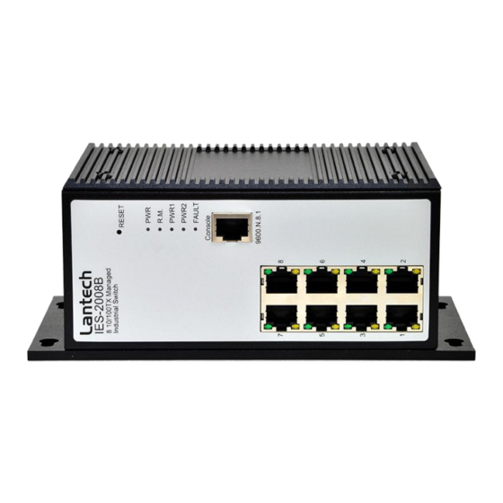
Chapter 2 Hardware Description In this paragraph, it will describe the Industrial switch’s hardware spec, port, cabling information, and wiring installation. 2.1 Physical Dimension 74.5mm x 105mm x 182mm (W x D x H) 2.2 Front Panel Front Panel of the industrial switch... -
Page 16: Top View
2.3 Top View The top panel of the Industrial Managed Industrial Switch has one terminal block connector of two DC power inputs and one fault alarm. Bottom Panel of the industrial switch... -
Page 17: Led Indicators
2.4 LED Indicators The diagnostic LEDs that provide real-time information of system and optional status are located on the front panel of the industrial switch. The following table provides the description of the LED status and their meanings for the switch. Color Status Meaning... - Page 18 The port is in half-duplex mode or no device is attached. A powered device is connected utilizing Green Power over Ethernet on the port FWD (P1 ~ Green No device is connected or power forwarding fails...
-
Page 19: Chapter 3 Hardware Installation
Chapter 3 Hardware Installation In this paragraph, we will describe how to install the Pro-Ring2s Managed Industrial Switch and the installation points attended to it. 3.1 Installation Steps Unpack the Industrial switch Power on the Industrial switch. Please refer to the Wiring the Power Inputs section for knowing the information about how to wire the power. -
Page 20: Wiring The Power Inputs
3.2 Wiring the Power Inputs Please follow the steps below to insert the power wire. 1. Insert AC or DC power wires into the contacts 1 and 2 for power 1, or 5 and 6 for power. 2. Tighten the wire-clamp screws for preventing the wires from loosing. [NOTE] The wire gauge for the terminal block should be in the range between 12 ~ 24 AWG. -
Page 21: Wiring The Fault Alarm Contact
3.3 Wiring the Fault Alarm Contact The fault alarm contacts are in the middle of the terminal block connector as the picture shows below. Inserting the wires, the switch will detect the fault status of the power failure, or port link failure (available for managed model) and then forms an open circuit. The following illustration shows an application example for wiring the fault alarm contacts. -
Page 22: Cabling
3.4 Cabling Use four twisted-pair, Category 5 or above cabling for RJ-45 port connection. The cable between the switch and the link partner (switch, hub, workstation, etc.) must be less than 100 meters (328 ft.) long. -
Page 23: Chapter 4. Network Application
Chapter 4. Network Application This chapter provides some sample applications to help user to have more actual idea of industrial switch function application. A sample application of the industrial switch is as below:... -
Page 24: Pro-Ring2S Application
Pro-Ring2s Application Pro-Ring II is a new Ring mechanism for Lantech Industrial Switches in which it eliminates the need to pre-set the Master switch in old Pro-Ring and yet to protect the network by much secure topologies than ever. Pro-Ring II works as a Ring Chain to reduce the risk of master switch linking down whereas the setup becomes much easier. -
Page 25: Chapter 5 Console Management
Chapter 5 Console Management 5.1 Connecting to the Console Port The supplied cable which one end is RS-232 connector and the other end is RJ-45 connector. Attach the end of RS-232 connector to PC or terminal and the other end of RJ-45 connector to the console port of the switch. -
Page 26: Login In The Console Interface
5.3 Login in the Console Interface When the connection between Switch and PC is ready, turn on the PC and run a terminal emulation program or Hyper Terminal and configure its communication parameters to match the following default characteristics of the console port: Baud Rate: 9600 bps Data Bits: 8 Parity: none... -
Page 27: Cli Management
5.4 CLI Management The system supports the console management—CLI command. After you log in on to the system, you will see a command prompt. To enter CLI management interface, type in “enable” command. CLI command interface... -
Page 28: Chapter 6 Web-Based Management
Chapter 6 Web-Based Management This section introduces the configuration and functions of the Web-Based management. 6.1 About Web-based Management There is an embedded HTML web site residing in flash memory on CPU board of the switch, which offers advanced management features and allows users to manage the switch from anywhere on the network through a standard browser such as Microsoft Internet Explorer. -
Page 29: System Login
6.3 System Login Launch the Internet Explorer on the PC Key in “http:// “+” the IP address of the switch”, and then Press “Enter”. The login screen will appear right after Key in the user name and password. The default user name and password are the same as ‘root’. -
Page 30: System
6.4 System 6.4.1 General – Switch Information User can find the system name, description, location and contact personnel to identify the switch. The version table below is a read-only field to show the basic information of the switch. System Name: Assign the system name of the switch (The maximum length is 64 bytes) ... - Page 31 Switch settings interface 6.4.2 General – CPU Load Average Sometimes the user was worry about that ‘ Could my switch process too many network packets ? So the network throughput was keeping decreasing “. In this option, you can monitor the CPU of switch to see if the switch was in full loading status or not.
-
Page 33: Time - Sntp
6.5 Time - SNTP SNTP (Simple Network Time Protocol) is a simplified version of NTP which is an Internet protocol used to synchronize the clocks of computers to some time reference. Because time usually just advances, the time on different node stations will be different. With the communicating programs running on those devices, it would cause time to jump forward and back, a non-desirable effect. - Page 34 PDT - Pacific Daylight PST - Pacific Standard -8 hours 4 am ADT - Alaskan Daylight ALA - Alaskan Standard -9 hours 3 am HAW - Hawaiian -10 hours 2 am Standard Nome, Alaska -11 hours 1 am CET - Central European FWT - French Winter MET - Middle European +1 hour...
- Page 35 Guam Standard, USSR Zone 9 IDLE - International Date Line NZST - New Zealand +12 hours Midnight Standard NZT - New Zealand SNTP Sever Address: Set the SNTP server IP address. You can assign a local network time server IP address or an internet time server IP address. ...
-
Page 36: Account - Admin
SNTP Configuration interface 6.6 Account - Admin Change web management login user name and password for the management security issue. User name: Type in the new user name (The default is ‘root’) New Password: Type in the new password (The default is ‘root’) ... -
Page 37: Ip Addressing - Ipv4
6.7 IP Addressing – IPV4 The switch is a network device which needs to be assigned an IP address for being identified on the network. Users have to decide a means of assigning IP address to the switch. DHCP Client: Enable or disable the DHCP client function. When DHCP client function is enabled, the switch will be assigned an IP address from the network DHCP server. - Page 38 IP Addressing interface...
-
Page 39: Syslog
6.8 Syslog This page allows the user to decide whether to send the system event log, and select the mode which the system event log will be sent to client only, server only, or both client and server. What kind of event log will be issued to the client/server depends on the selection on the Event Configuration tab. -
Page 40: Snmp Configuration
6.9 SNMP Configuration Simple Network Management Protocol (SNMP) is the protocol developed to manage nodes (servers, workstations, routers, switches and hubs etc.) on an IP network. SNMP enables network administrators to manage network performance, find and solve network problems, and plan for network growth. Network management systems learn of problems by receiving traps or change notices from network devices implementing SNMP. - Page 41 SNMP Agent Configuration interface...
-
Page 42: Snmp Trap Configuration
6.20.1 SNMP Trap Configuration A trap manager is a management station that receives the trap messages generated by the switch. If no trap manager is defined, no traps will be issued. To define a management station as a trap manager, assign an IP address, enter the SNMP community strings, and select the SNMP trap version. -
Page 43: System Alert - Relay Alarm
6.10 System Alert - Relay Alarm The Fault Relay Alarm function provides the Power Failure and Port Link Down/Broken detection. With both power input 1 and power input 2 installed and the check boxes of power 1/power 2 ticked, the FAULT LED indicator will then be possible to light up when any one of the power failures occurs. - Page 44 Change, and Port Event—available to be issued as the e-mail alert. Besides, this function provides the authentication mechanism including an authentication step through which the client effectively logs in to the SMTP server during the process of sending e- mail alert. ...
-
Page 45: System Alert - Event
6.8.2 System Alert - Event Having ticked the Syslog/SMTP checkboxes, the event log/email alert will be sent to the system log server and the SMTP server respectively. Also, Port event log/alert (link up, link down, and both) can be sent to the system log server/SMTP server respectively by setting the trigger condition. - Page 46 respectively. SNMP Authentication Failure: When the SNMP authentication fails, the system will issue the event log/email alert to the system log/SMTP server respectively. Event Configuration interface...
-
Page 47: Dhcp Server
6.11 DHCP Server DHCP is the abbreviation of Dynamic Host Configuration Protocol that is a protocol for assigning dynamic IP addresses to devices on a network. With dynamic addressing, a device can have a different IP address every time it connects to the network. In some systems, the device's IP address can even change while it is still connected. -
Page 48: Client Table
6.6.2 Client Table When the DHCP server function is enabled, the system will collect the DHCP client information including the assigned IP address, the MAC address of the client device, the IP assigning type, status and lease time. 6.6.3 IP Bindings Assign the dynamic IP address bound with the port to the connected client. -
Page 50: Port - Configuration
6.12 Port - Configuration In Port control you can configure the settings of each port to control the connection parameters, and the status of each port is listed beneath. Port No.: The port number which you want to be configured. ... -
Page 51: Port Status
6.13 Port Status It will show you the status of port configuration setting . -
Page 52: Port Statistics
6.14 Port Statistics The following chart provides the current statistic information which displays the real-time packet transfer status for each port. The user might use the information to plan and implement the network, or check and find the problem when the collision or heavy traffic occurs. - Page 53 Port Statistics interface...
-
Page 54: Port - Port Alert
Port – Port Alert 6.15 Having ticked the Syslog/SMTP checkboxes, the event log/email alert will be sent to the system log server and the SMTP server respectively. Also, Port event log/alert (link up, link down, and both) can be sent to the system log server/SMTP server respectively by setting the trigger condition. -
Page 55: Rate Control -Rate Limit
Rate Control –Rate Limit 6.16 You can set up every port’s bandwidth rate and frame limitation type. All the ports support port egress rate control. For example, assume port 1 is 10Mbps, users can set it’s effective egress rate is 1Mbps, ingress rate is 500Kbps. The switch performs the ingress rate by packet counter to meet the specified rate ... - Page 56 Storm Control: select the frame type that wants to filter. There are four frame types for selecting: Broadcast/Multicast/Flooded Unicast Broadcast/Multicast Broadcast only Broadcast/Multicast/Flooded Unicast, Broadcast/Multicast and Bbroadcast only types are only for ingress frames. The egress rate only supports All type. ...
-
Page 57: Aggregation - Configuration
6.17 Aggregation - Configuration Port trunking is the combination of several ports or network cables to expand the connection speed beyond the limits of any one single port or network cable. Link Aggregation Control Protocol (LACP), which is a protocol running on layer 2, provides a standardized means in accordance with IEEE 802.3ad to bundle several physical ports together to form a single logical channel. - Page 58 trunk group. TYPE: When choose LACP, the trunk group is using LACP. A port which joins an LACP trunk group has to make an agreement with its member ports first. Please notice that a trunk group, including member ports split between two switches, has to enable the LACP function of the two switches.
- Page 59 Port Trunk—Aggregator Setting interface (four ports are added to the left field with LACP enabled)
-
Page 60: Aggregator - Status
6.17.2 Aggregator – Status You can check the setting of Port aggregation in Status. -
Page 61: Spanning Tree
6.18 Spanning Tree The Rapid Spanning Tree Protocol (RSTP) is an evolution of the Spanning Tree Protocol and provides for faster spanning tree convergence after a topology change. The system also supports STP and the system will auto-detect the connected device that is running STP or RSTP protocol. - Page 62 the port concerned can only be connected to exactly another bridge (i.e. it is served by a point-to-point LAN segment), or can be connected to two or more bridges (i.e. it is served by a shared medium LAN segment). This function allows the P2P status of the link to be manipulated administratively.
-
Page 63: Rstp Information
6.18.2 RSTP Information This web page provides the port and switch information about RSTP. RSTP System Configuration interface... -
Page 64: Pro-Ring Ii S
6.19 Pro-Ring II S Pro-Ring IIs is a new Ring mechanism for Lantech Industrial Switches in which it protects the network by flexible topology than ever. Pro-Ring IIs works as a Single Ring and Multiple Ring to recover the broken ring in less than 20 ms for up to 50 switch nodes.. -
Page 65: Multicast Support
6.20 Multicast Support The Internet Group Management Protocol (IGMP) is an internal protocol of the Internet Protocol (IP) suite. IP manages multicast traffic by using switches, routers, and hosts that support IGMP. Enabling IGMP allows the ports to detect IGMP queries, report packets, and manage IP multicast traffic through the switch. - Page 66 IGMP Configuration interface 6.20.2 Static Filtering Multicasts are similar to broadcasts, they are sent to all end stations on a LAN or VLAN. Multicast filtering is the function, which end stations can receive the multicast traffic if the connected ports had been included in the specific multicast groups. With multicast filtering, network devices only forward multicast traffic to the ports that are connected to the registered end stations.
- Page 67 field and click to remove it. Delete...
-
Page 68: Lldp
6.21 LLDP Link Layer Discovery Protocol (LLDP) is defined in the IEEE 802.1AB, it is an emerging standard which provides a solution for the configuration issues caused by expanding LANs. LLDP specifically defines a standard method for Ethernet network devices such as switches, routers and wireless LAN access points to advertise information about themselves to other nodes on the network and store the information they discover. -
Page 69: Lldp Neighbors
6.22.1 LLDP Neighbors It will show you the information about Port Neighbor via LLDP protocol. -
Page 70: Filtering Database
6.23 Filtering Database Use the MAC address table to ensure the port security. 6.23.1 Configuration MAC Address Configuration:: Set the Aging time of MAC address table and define the event about port fail will influent the MAC table automatically or not. ... - Page 71 You can monitor the learning status of MAC address table in this function..
-
Page 72: Vlan
6.24 VLAN A Virtual LAN (VLAN) is a logical network grouping that limits the broadcast domain, which would allow you to isolate network traffic, so only the members of the same VLAN will receive traffic from the ones of the same VLAN. Basically, creating a VLAN on a switch is logically equivalent of reconnecting a group of network devices to another Layer 2 switch. - Page 73 802.1Q VLAN Setting: Enable GVRP mode and define the Management VLAN ID. GVRP (GARP VLAN Registration Protocol or Generic VLAN Registration Protocol) is a protocol that facilitates control of virtual local area networks (VLANs) within a larger network . GVRP conforms to the IEEE 802.1Q specification, which defines a method of tagging frames with VLAN configuration data.
- Page 74 The trunk port has to be connected to a trunk/hybrid port of the other switch. Both the tagged VID of the two ports have to be the same. 3. Hybrid Link: A segment which consists of Access and Trunk links. The hybrid port has both the features of access and trunk ports.
-
Page 75: Switch Status
6.24.2 Switch Status You can see the status of VLAN setting in this function.. -
Page 76: Qos
6.25 QoS Quality of Service (QoS) is the ability to provide different priority to different applications, users or data flows, or to guarantee a certain level of performance to a data flow. QoS guarantees are important if the network capacity is insufficient, especially for real-time streaming multimedia applications such as voice over IP or Video Teleconferencing, since these often require fixed bit rate and are delay sensitive, and in networks where the capacity is a limited resource, for example in cellular data communication. -
Page 77: Port Priority
6.25.2 Port Priority Configure the priority level for each port. With the drop-down selection item of Priority Type above being selected as Port-based, this control item will then be available to set the queuing policy for each port. Port x: Each port has 4 priority levels—High, Middle, Low, and Lowest—to be chosen. -
Page 78: Cos Mapping To Queue
6.25.3 COS Mapping to Queue Set up the COS priority level. With the drop-down selection item of Priority Type above being selected as COS only/COS first, this control item will then be available to set the queuing policy for each port. ... -
Page 79: Dscp Mapping To Queue
6.25.4 DSCP mapping to queue Set up the DSCP priority. With the drop-down selection item of Priority Type above being selected as DSCP only/SDCP first, this control item will then be available to set the queuing policy for each port. ... - Page 80 highest priority. Click to have the configuration take effect. Apply...
-
Page 81: Port Mirroring
6.25. Port Mirroring The Port mirroring is a method for monitor traffic in switched networks. Traffic through ports can be monitored by one specific port, which means traffic goes in or out monitored (source) ports will be duplicated into mirror (destination) port. ... -
Page 82: Security
6.26. Security You can block the un-authorized client in this function. 6.26.1 IP Source Guard - Configuration IP Source Guard function allows the user to assign 10 specific IP addresses that have permission to manage the switch through the http and telnet services for the securing switch management. -
Page 83: Ip Source Guard - Static Table
6.26.2 IP Source Guard – Static Table Security IP 1 ~ 10: The system allows the user to assign up to 10 specific IP addresses for access security. Only these 10 IP addresses can access and manage the switch through the HTTP/Telnet service once IP Security Mode is enabled. ... -
Page 84: X/Radius
6.26.3 802.1X/Radius 802.1x is an IEEE authentication specification which prevents the client from accessing a wireless access point or wired switch until it provides authority, like the user name and password that are verified by an authentication server (such as RADIUS server). After enabling the IEEE 802.1X function, you can configure the parameters of this function. - Page 85 6.26.3.2 Port Setting You can configure the 802.1x authentication state for each port. The state provides Disable, Accept, Reject, and Authorize. Reject: The specified port is required to be held in the unauthorized state. Accept: The specified port is required to be held in the authorized state. ...
- Page 86 6.26.3.3 Port Status You can monitor the port Authorized state in this function.
-
Page 87: Mac Filtering
6.26.4 MAC Filtering You can block the un-authorized MAC by switch in this function. -
Page 88: Port Security
6.26.5 Port Security You can block the un-authorized MAC by oer port in this function. -
Page 89: Maintenance
6.27. Maintenance 6.27.1 Save Configuration Save the current setting of switch .. 6.27.2 Restart Device Make the switch warm start. 6.27.3 Factory Defaults Reset switch to default configuration. Click “Reset” to reset all configurations to the default value. - Page 90 6.27.4 Firmware Upgrade TFTP Server IP Address: Type in your TFTP server IP. Firmware File Name: Type in the name of the firmware image file to be updated. Click Upgrade You can also browser the firmware on your hard drive by web update.
- Page 91 6.27.5 Export/Import You can restore a previous backup configuration from the TFTP server to recover the settings. Before doing that, you must locate the image file on the TFTP server first and the switch will download back the flash image. ...
- Page 92 6.27.6 Diagnostics 6.27.6.1 Ping You can ping other network device in this function.
-
Page 93: Troubles Shooting
Troubles shooting Verify that is using the right power cord/adapter (DC 24-48V), please don’t use the power adapter with DC output higher than 48V, or it may damage this device. Select the proper UTP/STP cable to construct the user network. Use unshielded twisted-pair (UTP) or shield twisted-pair (STP) cable for RJ-45 connections that depend on the connector type the switch equipped: 100Ω... -
Page 94: Appendix A-Rj-45 Pin Assignment
Appendix A—RJ-45 Pin Assignment RJ-45 Pin Assignments The UTP/STP ports will automatically sense for Fast Ethernet (10Base-T/100Base-TX connections), or Gigabit Ethernet (10Base-T/100Base-TX/1000Base-T connections). Auto MDI/MDIX means that the switch can connect to another switch or workstation without changing straight through or crossover cabling. See the figures below for straight through and crossover cable schematic. - Page 95 10/100Base-TX Cable Schematic The following two figures show the 10/100Base-TX cable schematic. Straight-through cable schematic Cross over cable schematic 10/100/1000Base-TX Pin outs The following figure shows the 10/100/1000 Ethernet RJ-45 pin outs. 10/100/1000Base-TX Cable Schematic...
- Page 96 Straight through cables schematic Cross over cables schematic...
-
Page 97: Appendix B-Command Sets
Appendix B—Command Sets Commands Set List User EXEC Privileged EXEC Global configuration VLAN database Interface configuration Lantech Commands Level Description Example Enter Privileged EXEC switch>enable enable mode quit Logout command line switch>quit shell show Show switch switch>show config configuration uptime Show system up time switch>uptime... -
Page 98: Admin Password Commands Set
Set switch system switch>enable [System Contact] contact window string switch#configure switch(config)#system contact show system-info Show system switch>show system-info information Admin Password Commands Set Lantech Commands Level Description Example admin username Changes a login switch>enable [Username] username. switch#configure (maximum 10 words) switch(config)#admin username... -
Page 99: Sntp Commands Set
Disable DHCP client switch>enable function of switch switch#configure switch(config)#no ip dhcp SNTP Commands Set Lantech Commands Level Description Example sntp enable Enable SNTP function switch>enable switch#configure switch(config)#sntp enable sntp ip Set SNTP server IP, if switch>enable... -
Page 100: Lldp Commands Set
Disable SNTP function switch>enable switch#configure switch(config)#no sntp no sntp daylight Disable daylight switch>enable saving time switch#configure switch(config)#no sntp daylight LLDP Commands Set Lantech Commands Level Description Example lldp enable Enable LLDP function switch>enable switch#configure switch(config)# lldp enable Configure LLDP switch>enable lldp interval... -
Page 101: Backup & Restore Commands Set
Show LLDP switch>enable information switch#show lldp no lldp Disable LLDP switch>enable switch#configure switch(config)#no lldp Backup & Restore Commands Set Lantech Commands Level Description Defaults Example tftp [server IP] backup Save configuration to switch>enable TFTP and need to switch#configure [file name]... - Page 102 switch(config)#dhcpserver lowip 192.168.1.100 Configure high IP switch>enable dhcpserver highip [High IP] address for IP pool switch#configure switch(config)#dhcpserver highip 192.168.1.200 dhcpserver subnetmask Configure subnet switch>enable mask for DHCP clients switch#configure [Subnet mask] switch(config)#dhcpserver subnetmask 255.255.255.0 dhcpserver gateway Configure gateway for switch>enable [Gateway] DHCP clients switch#configure...
-
Page 103: Port Control Commands Set
DHCP switch#show dhcpserver ip- server binding no dhcpserver Disable DHCP server switch>enable function switch#configure switch(config)#no dhcpserver Port Control Commands Set Lantech Commands Level Description Example interface fastEthernet Choose the port for switch>enable modification. switch#configure [Portid] switch(config)#interface fastEthernet 2... - Page 104 the port isn’t a giga port.. flowcontrol mode Configure flow control switch>enable [symmetric|asymmetric] switch#configure switch(config)#interface fastEthernet 2 switch(config-if)# flowcontrol mode asymmetric no flowcontrol Disable flow control of switch>enable interface switch#configure switch(config)#interface fastEthernet 2 switch(config-if)# no flowcontrol security enable Enable security of switch>enable interface switch#configure...
-
Page 105: Port Status Commands Set
2 switch(config-if)#show interface configuration Port Status Commands Set Lantech Commands Level Description Example show interface status show interface actual switch>enable status switch#configure switch(config)#interface fastEthernet 2 switch switch (config-if)#show interface status Rate Limit Commands Set Lantech Commands Level Description... -
Page 106: Trunk Commands Set
Show interfaces switch>enable bandwidth control switch#configure switch(config)#interface fastEthernet 2 switch(config-if)#show ratelimit Trunk Commands Set Lantech Commands Level Description Example aggregator priority Set port group system switch>enable [1~65535] priority switch#configure switch(config)#aggregator priority aggregator group Assign a trunk group switch>enable... - Page 107 [Workport] list, This parameter could be a port switch(config)#aggregator group range(ex.1-4) or a port 2 1,4,3 lacp workp 3 list separate by a comma(ex.2, 3, 6) [Workport]: The amount of work ports, this value could not be less than zero or be large than the amount of member ports.
-
Page 108: Pro-Ring Iis Commands Set
1 Remove a trunk group switch>enable no aggregator group [GroupID] switch#configure switch(config)#no aggregator group 1 PRO-RING IIS Commands Set Lantech Commands Level Description Example prorstp enable Enable PRO-RING IIS switch>enable for this interface switch#configure switch(config)#interface fastEthernet 2 switch(config-if)# prorstp enable... - Page 109 rstp priority [0~61440] Configure RSTP switch>enable bridge priority switch#configure parameter switch(config)#rstp priority 4096 rstp max-age [6~40] Configure RSTP max switch>enable age parameter switch#configure switch(config)#rstp max-age 6 rstp hello-time [1~10] Configure RSTP hello switch>enable time parameter. switch#configure switch(config)#rstp hello-time 1 rstp forward-time [4~30] Configure RSTP switch>enable...
-
Page 110: Vlan Commands Set
Show RSTP switch>enable information. switch#show rstp no rstp Disable RSTP. switch>enable switch#configure switch(config)#no rstp VLAN Commands Set Lantech Commands Level Description Example vlan database Enter VLAN configure switch>enable mode switch#vlan database vlanmode To set switch VLAN switch>enable [portbase| 802.1q | mode. - Page 111 [GroupID] port switch(vlan)#vlan port-based [PortNumbers] grpname test grpid 2 port 2,3,4 show vlan [GroupID] Show VLAN switch>enable information switch#vlan database show vlan switch(vlan)#show vlan 2 no vlan [VID] Delete port base switch>enable group ID switch#vlan database switch(vlan)#no vlan 2 IEEE 802.1Q VLAN Configure switch>enable vlan 8021q mnt-vid...
- Page 112 [UntaggedVID] port belong to a trunk switch(vlan)#vlan 8021q port 3 group, this command hybrid-link untag 4 tag 3,6,8 [TaggedVID List] can’t be applied. switch(vlan)#vlan 8021q port 3 hybrid-link untag 5 tag 6-8 vlan 8021q port Assign a qinq link for switch>enable [PortNumber] VLAN by port, if the...
-
Page 113: Snmp Commands Set
2 no vlan [GroupID] Delete port base switch>enable group ID switch#vlan database switch(vlan)#no vlan 2 SNMP Commands Set Lantech Commands Level Description Example snmp agent-mode Select the agent mode switch>enable [v1v2c|v3] of SNMP switch#configure switch(config)#snmp agent-mode... -
Page 114: Traffic Prioritization Commands Set
Remove SNMPv3 switch>enable user profile password switch#configure [Authentication switch(config)#no snmp snmpv3- Password] [Privacy user root password 123 123 Password] Traffic Prioritization Commands Set Lantech Commands Level Description Example qos prioritytype Setting of QOS priority switch>enable [port-based|cos- type switch#configure only|tos-only|cos- switch(config)#qos prioritytype... -
Page 115: Igmp Commands Set
QoS switch#configure configuration switch#show qos no qos Disable QoS function switch>enable switch#configure switch(config)#no qos IGMP Commands Set Lantech Commands Level Description Example igmp enable Enable IGMP switch>enable snooping function switch#configure switch(config)#igmp enable igmp query Configure IGMP query switch>enable... -
Page 116: Multicast Static Filtering Table Commands Set
Disable IGMP switch>enable snooping function switch#configure switch(config)#no igmp no igmp query Disable IGMP query switch>enable switch#configure switch(config)#no igmp query Multicast Static Filtering Table Commands Set Lantech Commands Level Description Example multicast-filtering Configure multicast switch>enable [IP_addr] filtering entry of switch#configure interface. switch(config)#interface... -
Page 117: Ip Security Commands Set
2 switch(config-if)#no multicast- filtering 225.100.100.100 show multicast-filtering Show multicast switch>enable filtering table switch# show multicast-filtering IP Security Commands Set Lantech Commands Level Description Example security enable Enable IP security switch>enable function switch#configure switch(config)#security enable security http Enable IP security of switch>enable... -
Page 118: Port Security Commands Set
Disable IP security of switch>enable SNMP server switch#configure switch(config)#no security snmp Port Security Commands Set Lantech Commands Level Description Example mac-address-table static Configure MAC switch>enable hwaddr address entry of switch#configure [HW-Addr] interface (static). switch(config)#interface... -
Page 119: Commands Set
MAC address table switch#configure [HW-Addr] (filter) switch(config)#no mac-address- table filter hwaddr 000012348678 802.1x Commands Set Lantech Commands Level Description Example 8021x enable Enable IEEE802.1x switch>enable function switch#configure switch(config)# 8021x enable 8021x system radiusip Use the 802.1x switch>enable system radius IP... - Page 120 8021x misc quietperiod Use the 802.1x misc switch>enable [Seconds] quiet period global switch#configure configuration switch(config)# 8021x misc command to specify quietperiod 10 the quiet period value of the switch. 8021x misc txperiod Use the 802.1x misc switch>enable TX period global switch#configure [Seconds] configuration...
-
Page 121: Fault Alarm Commands Set
8021x and also the port sates. no 8021x Disable 802.1x switch>enable function switch#configure switch(config)#no 8021x Fault Alarm Commands Set Lantech Commands Level Description Example fault-relay power Configure Relay Alarm switch>enable for Power Failure switch#configure [number] [enable/disable] switch(config)#fault-relay power 1... - Page 122 systemlog ip Set System log server switch>enable [IP address] IP address. switch#configure switch(config)# syslog ip 192.168.1.100 show syslog Show SYSLOG switch>enable configuration and log switch#configure table. switch#show syslog Disable systemlog switch>enable no syslog functon switch#configure switch(config)#no syslog smtp enable Enable SMTP function switch>enable switch#configure switch(config)#smtp enable smtp serverip...
- Page 123 smtp password Configure switch>enable [password] authentication switch#configure password switch(config)#smtp password 1234 smtp rcptemail Configure Rcpt e-mail switch>enable [Index] [Email address] Address switch#configure switch(config)#smtp rcptemail 1 Alert@test.com show smtp Show the information switch>enable of SMTP switch#show smtp no smtp Disable SMTP switch>enable function switch#configure...
-
Page 124: Mac Address Table Commands Set
Disable port event for switch>enable no event smpt SMTP switch#configure switch(config)#interface fastethernet 3 switch(config-if)#no event smtp Mac Address Table Commands Set Lantech Commands Level Description Example show mac-address-table Show MAC address switch>enable table switch#configure switch(config)#interface fastethernet 2... -
Page 125: Port Statistics Commands Set
30 auto-flush Auto flush mac switch>enable [enable|disable] address table when switch#configure ports link down switch(config)#auto-flush enable Port Statistics Commands Set Lantech Commands Level Description Example show interface show interface statistic switch>enable accounting counter switch#configure switch(config)#interface fastEthernet 2 switch switch (config-if)#show interface... -
Page 126: System Event Log Commands Set
Disable source port of switch>enable monitor function switch#configure switch(config)#interface fastEthernet 2 switch(config-if)#no monitor System Event Log Commands Set Lantech Commands Level Description Example show syslog Show SYSLOG switch>enable configuration and log switch#show syslog table. Ping Commands Set... -
Page 127: System Reboot Commands Set
Factory Default Commands Set Lantech Commands Level Description Example default Restore to factory switch>enable [keepip|keepadmin|both default configuration switch#configure switch(config)#default both System Reboot Commands Set Lantech Commands Level Description Example Reboot switch switch>enable reload switch#configure switch(config)#reload Logout Commands Set Lantech Commands...
Need help?
Do you have a question about the IES-2008B-DNV and is the answer not in the manual?
Questions and answers