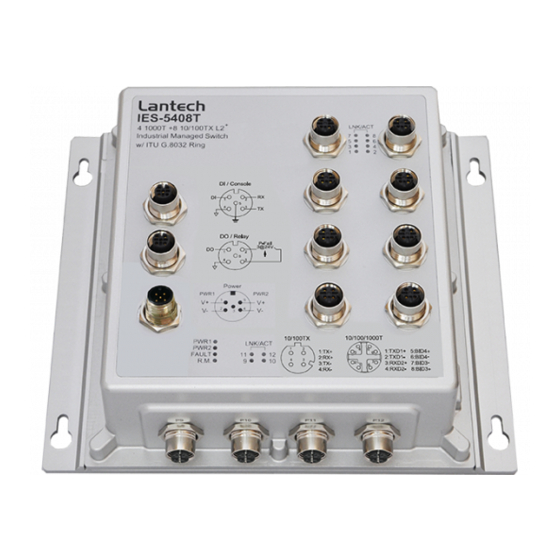
Lantech IPES-5408T User Manual
8 10/100tx + 4 1000t l2+
(w/8 poe at/af) industrial managed
switch w/itu g.8032 ring
Hide thumbs
Also See for IPES-5408T:
- User manual (21 pages) ,
- User manual (30 pages) ,
- User manual (30 pages)

Related Manuals for Lantech IPES-5408T


Summary of Contents for Lantech IPES-5408T
- Page 1 IPES/IES-5408T Series 8 10/100TX + 4 1000T L2 (w/8 PoE at/af) Industrial Managed Switch w/ITU G.8032 Ring User Manual IP-67 IP-43 Apr. 2014...
- Page 2 Recommendation for Shielded network cables STP cables have additional shielding material that is used to reduce external interference. The shield also reduces the emission at any point in the path of the cable. Our recommendation is to deploy an STP network cable in demanding electrical environments. Examples of demanding indoor environments are where the network cable is located in parallel with electrical mains supply cables or where large inductive loads such as motors or contactors are in close vicinity to the camera or its cable.
-
Page 3: Important Notice
Lantech Communications Global Inc. Products offered may contain software which is proprietary to Lantech Communications Global Inc. The offer or supply of these products and services does not include or infer any transfer of ownership. -
Page 4: Fcc Warning
FCC Warning This Equipment has been tested and found to comply with the limits for a Class-A digital device, pursuant to Part 15 of the FCC rules. These limits are designed to provide reasonable protection against harmful interference in a residential installation. This equipment generates, uses, and can radiate radio frequency energy. -
Page 5: Table Of Contents
Content Chapter 1 Introduction ..........7 Specification ............7 Chapter 2 Hardware Description ......12 Physical Dimension ........12 Package Content: ........14 IP Protection ..........15 LED Indicators ..........18 Chapter 3 Hardware Installation ......20 Chapter 4 Network Application ....... 25 4.1 ITU G.8032 Scheme........25 4.2 Ring Coupling ..........25 4.3 Multiple Rings ..........26 4.4 Dual Homing ..........27... - Page 6 6.4.3 IP configuration ............. 35 6.4.4 DHCP server ............36 6.4.5 System Time ............38 6.4.6 User Accounts – Access account management ... 41 6.4.7 SNMP Configuration ........... 42 6.4.8 Fault Relay Configuration ........43 6.4.9 Digital Input /Output ..........44 6.4.10 Environmental Monitoring ........
- Page 7 6.9 QoS ..............68 6.9.1 QoS Policy ............68 6.10 Security ............70 6.10.1 MAC Address Tables .......... 70 6.10.2 Access Control List ..........71 6.10.3 IEEE 802.1X Radius Server ....... 72 6.10.4 IP Security ............73 6.11 VLAN .............74 6.11.1 802.1Q VLAN Config .......... 74 6.11.2 Status ..............
- Page 8 6.15.3.2 Port ............ 92 6.15.4. MSTP MSTI Settings ......... 93 6.15.5. MSTP Bridges Status ........94 6.15.6. Bridge status of all ports ........95 6.16 Aggregation ..........96 6.16.1. Aggregation Configuration ......... 96 6.16.2 LACP Port Status ..........97 6.17 PTP IEEE 1588 v2 ........98 6.18 G.8032 ERPS ..........
-
Page 9: Chapter 1 Introduction
LLDP for Ciscoworks to detect the switch info to be shown on L2 map topology. The user friendly UI, innovative auto topology drawing and topology demo makes IES-5408T & IPES-5408T (IP67/IP43) series much easier to get hands-on. The complete CLI allows professional engineer to configure by command line. - Page 10 Protocol CSMA/CD Per unit: Power 1 (Green), Power 2 (Green), P-Fail (Red) Ethernet port: Link/Activity (Green), Speed (Green); GigaT: Link/Activity (Green) DI / DO 1 Digital Input (DI) : Level 0: -30~2V / Level 1: 10~30V Max. input current:8mA 1 Digital Output(DO): Open collector to 40 VDC, 200mA Operating Humidity 5% ~ 95% (Non-condensing) Operating Temperature...
- Page 11 IfAlias Each port allows an alphabetic string of 128-byte assigned as its own unique name via the SNMP or CLI interface *Future release **Optional IPES-5408T-8 series Hardware Specification Standards IEEE 802.3 10Base-T Ethernet IEEE 802.3u 100Base-TX IEEE 802.3ab 1000Base T IEEE802.3x Flow Control and Back Pressure...
- Page 12 DI / DO 1 Digital Input (DI) : Level 0: -30~2V / Level 1: 10~30V Max. input current:8mA 1 Digital Output(DO): Open collector to 40 VDC, 200mA Operating Humidity 5% ~ 95% (Non-condensing) Operating Temperature -40°C~75°C / -40°F~167°F Storage Temperature -40°C~85°C / -40°F~185°F Redundant Power Supply 12~56VDC for Ethernet Data...
- Page 13 Provide DNS client feature and support Primary and Secondary DNS server. SNTP Supports SNTP to synchronize system clock in Internet Firmware Upgrade Firmware upgrade via TFTP or Lantech InstaConfig** Configuration Supports text configuration file for system quick installation upload and download...
-
Page 14: Chapter 2 Hardware Description
Chapter 2 Hardware Description In this paragraph, it will describe the Industrial switch’s hardware spec, port, cabling information, and wiring installation. 2.1 Physical Dimension Aluminum case. IP-67, 285 (W) x 201.4 (D) x 84.4 (H) mm... - Page 15 Port description of IP-67 series switch Aluminum case. IP-43, 273 (W) x 188.4(D) x 84.4 (H) mm **The port description of IP-43 model is the same as of IP-67 one.
-
Page 16: Package Content
2.2 Package Content: Manual CD Product Console cable... -
Page 17: Ip Protection
2.3 IP Protection The IP Code, Ingress Protection Rating, sometimes also interpreted as International Protection Rating, classifies and rates the degree of protection provided against the intrusion (including body parts such as hands and fingers), dust, accidental contact, and water in mechanical casings and with electrical enclosures. It is published by the International Electrotechnical Commission (IEC) Solid particle protection The first digit indicates the level of protection that the enclosure provides against access... - Page 18 Liquid ingress protection The second digit indicates the level of protection that the enclosure provides against harmful ingress of water. Protected Level Testing for Details against — — protected Dripping Dripping water (vertically Test duration: 10 minutes water falling drops) shall have no Water equivalent to 1 mm harmful effect.
- Page 19 Powerful Water projected in powerful Test duration: at least water jets jets (12.5 mm nozzle) 3 minutes against the enclosure from Water volume: 100 litres per any direction shall have no minute harmful effects. Pressure: 100 kPa at distance of 3 m Immersion Ingress of water in harmful Test duration: 30 minutes...
-
Page 20: Led Indicators
2.4 LED Indicators The diagnostic LEDs that provide real-time information of system and optional status are located on the front panel of the industrial switch. The following table provides the description of the LED status and their meanings for the switch. Color Status Meaning... - Page 21 No device attached.
-
Page 22: Chapter 3 Hardware Installation
3.1.3 Connect the M23/M12 connector of power input. The PoE power supply for IPES-5408T series is connected via a 5-pole M23 female connector while IES-5408T is with a 5-pole M12 female connector. - Page 23 Pin assignment of Power input Redundant Power Input The power input can be supported redundantly. The supply voltage is electrically isolated from the housing. Note: With single power supply of the mains voltage, the device will report a power failure. You can disable this power fail event via web browser.
- Page 24 The chassis is grounded via a separate ground nut (M3). Use toothed locking washers for a good electrical connection. Ground screw of IPES-5408T switch 3.1.5 Connect the M12 connector with RJ-45 data cable, ports are not used shall be caped that comes with the package to insulate the...
- Page 25 Pin assignment of M12 10/100Tx network connector Pin assignment of M12 10/100/100T network connector...
- Page 26 3.1.6 Check the status of LED, make sure the switch was in working status. Note: The protection class IP67/IP43 is only achieved when bolted together. The other components attaching to the system have to meet with the IP67/IP43 protection class in order to reach the whole system IP 67/IP43 protection.
-
Page 27: Chapter 4 Network Application
Chapter 4 Network Application 4.1 ITU G.8032 Scheme LANTECH G.8032 protocol is following ITU (International Telecommunication Unit) G.8032 v2 draft. The benefits of G.8032 are: 1. <50ms recovery time when failover 2. G.8032 has defined the protocol scheme, parameters, functions, test measures to be unified that the users can evaluate the possible network infrastructure without literally testing each brand in large scale. -
Page 28: Multiple Rings
4.3 Multiple Rings... -
Page 29: Dual Homing
4.4 Dual Homing 4.5 Chain... -
Page 31: Chapter 5 Console Management
Chapter 5 Console Management 5.1 Connecting to the Console Port The supplied cable which one end is M12 5-pole connector and the other end is RS-232 connector. Attach the end of RS-232 connector to PC or terminal and the other end of M12 connector to the console port of the switch. - Page 32 The settings of communication parameters Having finished the parameter settings, click ‘OK’. When the blank screen shows up, press Enter key to have the login prompt appears. Key in ‘admin’ (default value) for both User name and Password (use Enter key to switch), then press Enter and the Main Menu of console management appears.
-
Page 33: Chapter 6 Web-Based Management
Chapter 6 Web-Based Management This section introduces the configuration and functions of the Web-Based management. 6.1 About Web-based Management There is an embedded HTML web site residing in flash memory on CPU board of the switch, which offers advanced management features and allows users to manage the switch from anywhere on the network through a standard browser such as Microsoft Internet Explorer. -
Page 34: System Login
6.3 System Login Launch the Internet Exploreron the PC(the switch also support Mozila and Chrome browser). Key in “http:// “+” the IP address of the switch”, and then Press “Enter”. The login screen will appear right after Key in the user name and password. The default user name and password are the same as ‘admin’. -
Page 35: System
6.4 System System Identification Configuration 6.4.1 Name: An administratively assigned name for this managed switch. By convention, this is the node's fully-qualified domain name. A domain name is a text string drawn from the alphabet (A-Z), digits (0-9), minus sign (-). No space characters are permitted as part of a name. -
Page 36: System Information
6.4.2 System Information User can find the system name, description, location and contact personnel to identify the switch. The version table below is a read-only field to show the basic information of the switch. -
Page 37: Ip Configuration
6.4.3 IP configuration The switch is a network device which needs to be assigned an IP address for being identified on the network. Users can select a methodof assigning IP address to the switch. DHCP Client: Enable or disable the DHCP client function. When DHCP client function is enabled, the switch will obtain an IP address from the network DHCP server automatically. -
Page 38: Dhcp Server
6.4.4 DHCP server DHCP is the abbreviation of Dynamic Host Configuration Protocol that is a protocol for assigning dynamic IP addresses to devices on a network. With dynamic addressing, a device can have a different IP address every time it connects to the network. - Page 39 address. IP Range(down): Type in an IP address. High IP address is the end of the dynamic IP range. For example, dynamic IP is in the range between 192.168.1.100 ~ 192.168.1.200. In contrast, 192.168.1.200 is the High IP address. ...
-
Page 40: System Time
6.4.4.1 DHCP status You can check the status of used DHCP IP in here. 6.4.5 System Time SNTP (Simple Network Time Protocol) is a simplified version of NTP which is an Internet protocol used to synchronize the clocks of computers to a specified time reference. - Page 41 Oscar Time Zone -2 hours 10 am ADT - Atlantic Daylight -3 hours 9 am AST - Atlantic Standard -4 hours 8 am EDT - Eastern Daylight EST - Eastern Standard -5 hours 7 am CDT - Central Daylight CST - Central Standard -6 hours 6 am MDT - Mountain Daylight...
- Page 42 ZP5 - USSR Zone 4 +5 hours 5 pm ZP6 - USSR Zone 5 +6 hours 6 pm WAST - West Australian +7 hours 7 pm Standard CCT - China Coast, +8 hours 8 pm USSR Zone 7 JST - Japan Standard, +9 hours 9 pm USSR Zone 8...
-
Page 43: User Accounts - Access Account Management
NTP Sever : Set the SNTP server IP address. You can assign a local network time server’s IP address or an internet time server’s IP address. Click to have the configuration take effect. Apply 6.4.6 User Accounts – Access account management There are 2 default accounts in switch –... -
Page 44: Snmp Configuration
6.4.7 SNMP Configuration Simple Network Management Protocol (SNMP) is the protocol developed to manage nodes (servers, workstations, routers, switches and hubs etc.) on an IP network. SNMP enables network administrators to manage network performance, find and solve network problems, and plan for network growth. Network management systems learn of problems by receiving traps or change notices from network devices implementing SNMP. -
Page 45: Fault Relay Configuration
A trap manager is a management station that receives the SNMP trap messages generated by the switch. If no trap manager is defined, no traps will be issued. To define a management station as a trap manager, assign an IP address, enterthe SNMP community strings, and select the SNMP trap version. -
Page 46: Digital Input /Output
Note: The interface of Port Link Down/Boken will be changed with different switch model automatically. 6.4.9 Digital Input /Output The IPES/IES Industrial Switch contains two digital outputs and two digital inputs. Outputs are open-collector transistor switches that may be controlled by the host computer. - Page 47 HighLow: Having focused this radio button, DI0/DI1 will only report the status when the external device’s voltage changes from high to low. Both: Having focused this radio button, DI0/DI1 will report both the status when the external device’s voltage changes from high to low or low to high. ...
-
Page 48: Environmental Monitoring
6.4.10 Environmental Monitoring You can monitor the Voltage 、Current、Consumption、Temp、and PoE Consumption(for the PoE series switch) in this function. -
Page 49: Event & Log
6.5 Event & Log 6.5.1 View Logs This will show you the log in local interface, you can press or F5 to refresh the web page and get the newest event log. -
Page 50: Events
6.5.2 Events 6.5.2.1 Environmental Monitoring Event You can set the trigger range of each event here, for example, if you set the blue bar in the range from 20V to 50V, when the voltage of power input is over 50VDC or lower than the 20VDC, it will trigger the event system. -
Page 51: Ddm Event
6.5.3 DDM event The switch supports DMI where can read all the parameters info from DDM SFP when plugged into SFP slots, the shown information is as above including SFP temperature, input voltage, TX bias, TX dBm and RX dBM. You can set the trigger range of each event here, for example, when you set the blue bar in the range from -45∘C to 90∘C, if the working Temp. -
Page 52: Actions
6.5.4 Actions 6.5.4.1 Local Log Action Save to Local: Save log to local file 6.5.4.2 Remote Syslog Action Log to Remote Syslog Server: Save log to Syslog Server... - Page 53 6.5.4.3 Email Action Email Alert: Sent log via Email 6.5.4.4 SMS Action SMS Alert: Sent log via SMS service. (The must connect with internet and define the SMS server before using this function)
- Page 54 (Currently the SMS service is offered by LANTECH in Taiwan.) 6.5.4.5 SNMP Trap Action SNMP Trap Action: The setting page of this function will be redirect to SNMP TRAP. 6.5.3.6 DOut Action DOUT Action: The setting page of this function will be redirect to Digital...
-
Page 55: Event Action Map
6.5.5 Event Action Map 6.5.5.1Event Actions: A. Choose the event which you want to active B. You will find the event which you select will be display as below, then choose forwarding method to define how to forward this event to manager side. - Page 56 C. You can set the forwarding method of port break event in here.
-
Page 57: Ports
6.6 Ports 6.6.1 Configuration In Port control you can configurethe settings of each port to control the connection parameters, and the status of each port is listed beneath. Port No.: The port number which you want to be configured. ... -
Page 58: Status
6.6.2 Status It will show you the status of port configuration setting. 6.6.3 Statistics The following chart provides the current statistic information which displays the real- time packet transfer status for each port. The user might use the information to plan and implement the network, or check and find the problem when the collision or heavy traffic occurs. -
Page 59: Iec Packet Statistics
Rx Bad Packet: The counts of receiving good packets (including undersize [less than 64 octets], oversize, CRC error, fragments and jabbers) via this port. Tx Abort Packet: The aborted packet while transmitting. Packet Collision: The counts of collision packet. ... -
Page 60: Rate Limiting
Mirrpr From:You can set which switch port will be duplicated then send to the destination port. Note1 : All the duplicated data of the source port can be separated with RX and TX, if you want to collect multi-source ports at the same time, you can assign the Tx of one destination port to be responsible for collecting all the Tx data of source ports and assign another RX of destination port to be responsible for collecting all the Rx data of source ports. -
Page 61: Loop Protection
6.6.7 Loop Protection The loop Protection is used to detect the presence of traffic. When switch receives packet’s (looping detection frame) MAC address the same as oneself from port, show Loop Protection happens. The port will be locked when it received the looping Protection frames. -
Page 62: Power Over Ethernet
6.7 Power over Ethernet (only available for IPES series) This segment shows the PoE(Power over Ethernet) function complying with IEEE 802.3af/at standards 6.7.1 Configuration Maximum Power Available: This function will limit the total power consumption and cannot exceed 250W. ... -
Page 63: Status
Power Limit Set the Maximum power of each PoE port 6.7.2 Status Power Consumption: Total power consumption of all PoE ports Main Voltage: The input voltage for PoE power source Main Current The input current for PoE power source ---------------------------------------------------------------------------------------------------------------- ... - Page 64 State The PoE state of the end device.(Unknown means the end device is none-PD device) Temperature Temperature of PoE chipset Current Output current of each PoE port Voltage Output Voltage of each PoE port Power Power consumption of each PoE port ...
-
Page 65: Detection
6.7.3 Detection The PoE detection function is to detect whether the connected PD is still alive by pinging the IP address. Should the PD is not responding, the switch can be set for consequence action such as rebooting PD etc. Note: The PD must have IP address. ... -
Page 66: Scheduling
Interval How frequent the switch will ping the IP address of PD. Retry Time How many times of ping failure the switch will define the PD as dead or failure. Failure Log Failure times of the PD detection. ... -
Page 67: Topology
6.8 Topology This function can help user to build the network topology drawing automatically for the switches that are in closed looped and show the detail information of each switch node by clicking the icon. The topology view drawing can show the backup path with the dot line for overall picture, please remember to enable LLDP function before you use this function. - Page 68 Text View: Display each switch in your network by text. The Topology was build with the information from LLDP where can let you see the information from other switches. Nodes: show the information of each switch like MAC address and IP address. ...
- Page 69 Demo: Demo display each topology in different connection.
-
Page 70: Qos
6.9 QoS Quality of Service (QoS) is the ability to provide different priority to different applications, users or data flows, or to guarantee a certain level of performance to a data flow. QoS guarantees are important if the network capacity is insufficient, especially for real-time streaming multimedia applications such as voice over IP or Video Teleconferencing, since these often require fixed bit rate and are delay sensitive, and in networks where the capacity is a limited resource, for example in... - Page 71 Priority Type There are 3 priority type selections available—CoS, TOS-only, TOS first, . Disable means no priority type is selected. Set up the COS priority level. With the drop-down selection item of Priority Type above being selected as COS only/COS first, this control item will then be available to set the queuing policy for each port.
-
Page 72: Security
6.10 Security 6.10.1 MAC Address Tables Use the MAC address table to ensure the port security. Static MAC Address You can add a static MAC address; it remains in the switch's address table, regardless of whether the device is physically connected to the switch. This saves the switch from having to re-learn a device's MAC address when the disconnected or powered-off device is active on the network again. -
Page 73: Access Control List
6.10.2 Access Control List The switch access control list (ACL) is probably the most commonly used object in the OSI layer 2 and 3. It is used for access filtering. The ACLs are divided into MAC and IP filtering. 6.10.2.1 ACL with Layer2 (MAC) ... -
Page 74: Ieee 802.1X Radius Server
6.10.3 IEEE 802.1X Radius Server 802.1X is an IEEE authentication specification which prevents the client from accessing a wireless access point or wired switch until it provides authority, like the user name and password that are verified by an authentication server (such as RADIUS server). -
Page 75: Ip Security
6.10.4 IP Security IP security function allows user to assign 20 specific IP addresses that have permission to access the switch through the web browser for the securing switch management. Enable IP Security When this option is in Enable mode, the Enable Web Server and Enable Telnet Server and Enable SSH Server check boxes will then be available. -
Page 76: Vlan
6.11 VLAN A Virtual LAN (VLAN) is a logical network grouping that limits the broadcast domain, which would allow you to isolate network traffic, so only the members of the same VLAN will receive traffic from the ones of the same VLAN. Basically, creating a VLAN on a switch is logically equivalent of reconnecting a group of network devices to another Layer 2 switch. - Page 77 link, has an untagged VID (also called PVID). After an untagged frame gets into the access port, the switch will insert a four-byte tag in the frame. The contents of the last 12-bit of the tag is untagged VID. When this frame is sent out through any of the access port of the same PVID, the switch will remove the tag from the frame to recover it to what it was.
-
Page 78: Status
Assign a number in the range between 1 and 4094. 6.11.2 Status You can see the status of each VLAN group in here. 6.12 MVR The MVR feature enables multicast traffic forwarding on the Multicast VLAN. In a multicast television application, a PC or a television with a set-top box can receive the multicast stream. -
Page 79: Lldp
6.12 LLDP Link Layer Discovery Protocol (LLDP) is defined in the IEEE802.1AB, it is an emerging standard which provides a solution for the configuration issues caused by expanding LANs. LLDP specifically defines a standard method for Ethernetnetwork devices such as switches, routers and wireless LAN access points to advertise information about themselves to other nodes on the network and store the information they discover. -
Page 80: Lldp Neighbor
The switch periodically transmits LLDP frames to its neighbours for having the network discovery information up-to-date. The interval between each LLDP frame is determined by the Tx Interval value. Valid values are restricted to 5 - 32768 seconds. The LLDP port settings relate to the currently selected stack unit, as reflected by the page header. - Page 81 The port on which the LLDP frame was received. Chassis ID The Chassis ID is the identification of the neighbor's LLDP frames. Remote Port ID The Remote Port ID is the identification of the neighbor port. Port Description Port Description is the port description advertised by the neighbor unit.
-
Page 82: Lldp Statistics
the neighbor's IP address. 6.12.3 LLDP Statistics This page provides an overview of all LLDP traffic. Two types of counters are shown. Total are counters that refer to the whole stack, switch, while Port refer to per port counters for the currently selected switch. 6.12.3.1 Total ... - Page 83 The number of LLDP frames transmitted on the port. TLVs Discarded Each LLDP frame can contain multiple pieces of information, known as TLVs (TLV is short for "Type Length Value"). If a TLV is malformed, it is counted and discarded. TLVs Unrecognized The number of well-formed TLVs, but with an unknown type value.
-
Page 84: Cdp
TLVs Unrecognized The number of well-formed TLVs, but with an unknown type value. 6.13 CDP The Cisco Discovery Protocol (CDP) is a proprietary data link layer protocol developed by Cisco. It is used to share information about other directly connected Cisco equipment, such as the OS version and IP address 6.13.1 CDP Configuration Device Settings ... -
Page 85: Cdp Port Configuration
frame shall be considered valid. The holdtime between each CDP frame is determined by the Tx Holdtime value. Valid values are restricted to 5 - 32768 seconds. 6.13.2 CDP Port Configuration Port The switch port number of the logical CDP port. ... - Page 86 detected. The columns hold the following information: Local Port The port on which the CDP frame was received. Version Version is the CDP version advertised by the neighbor unit. Ageout TTL Ageout TTL is the ageout Time-To-Live advertised by the neighbor unit. Device ID The Device ID is the identification of the neighbor's CDP frames.
-
Page 87: Igmp Snooping
6.14 IGMP Snooping The switch support IP multicast, you can enable IGMP protocol on web management’s switch setting configuration page, then the IGMP snooping information displays. IP multicast addresses range are from 224.0.0.0 through 239.255.255.255. -
Page 88: Igmp Snooping Configuration
6.14.1 IGMP Snooping Configuration 6.14.1.1 Global Configuration Enable Query: enable or disable the IGMP query function. The IGMP query information will be displayed in IGMP status section. Enable Snooping: enable or disable the IGMP protocol. Flood Well-known Multicasr traffic:let the switch know how to process the Multicast data stream which was unregistered with IGMP Query. -
Page 89: Igmp Snooping Status
6.14.2 IGMP Snooping Status 6.14.2.1 Statistics VLAN ID The VLAN ID of the entry. Status Querior Shows the Querior status is "ACTIVE" or "IDLE". "DISABLE" denotes the specific interface is administratively disabled. Queries Transmitted The number of Transmitted Queries. ... - Page 90 V3 Reports Received The number of Received V3 Reports. V2 Leaves Received The number of Received V2 Leaves. IGMP Groups Entries in the IGMP Group Table are shown on this page. VLAN ID VLAN ID of the group. ...
-
Page 91: Mstp
6.15 MSTP The section describes that how to configure the Spanning Tree Bridge and STP System settings. It allows you to configure STP System settings are used by all STP Bridge instance in the Switch. 6.15.1. MSTP Global Configuration Mode Show the STP protocol version setting. -
Page 92: How To Enable Mstp
The delay used by STP Bridges to transit Root and Designated Ports to Forwarding (used in STP compatible mode). Valid values are in the range 4 to 30 seconds. Max Age The maximum age of the information transmitted by the Bridge when it is the Root Bridge. - Page 93 6.15.2.3 Remember to press “Apply” 6.15.2.4 Save setting...
-
Page 94: Cist Settings
6.15.3 CIST Settings 6.15.3.1 Bridge configuration VLANs Mapped The list of VLANs mapped to the MSTI. The VLANs must be separated with comma and/or space. A VLAN can only be mapped to one MSTI. An unused MSTI should just be left empty. (I.e. not having any VLANs mapped to it.) Unmapped VLANs are mapped to the CIST. -
Page 95: Mstp Msti Settings
edge_mode Control whether the oper Edge flag should start as being set or cleared. (The initial oper Edge state when a port is initialized). Control whether the bridge should enable automatic edge detection on the bridge port. This allows oper Edge to be derived from whether BPDU's are received on the port or not. -
Page 96: Mstp Bridges Status
6.15.5. MSTP Bridges Status Instance The Bridge Instance. ex: CIST, MSTI1, ... Bridge ID The Bridge ID of this Bridge instance. Root ID The Bridge ID of the currently elected root bridge. Root Port The switch port currently assigned the root port role. ... -
Page 97: Bridge Status Of All Ports
6.15.6. Bridge status of all ports Port The switch port number of the logical STP port. Role The current STP port role of the port. The port role can be one of the following values: AlternatePort BackupPort RootPort DesignatedPort Disabled. ... -
Page 98: Aggregation
6.16 Aggregation Port trunking is the combination of several ports or network cables to expand the connection speed beyond the limits of any one single port or network cable. Link Aggregation Control Protocol (LACP),which is a protocol running on layer 2, provides a standardized means in accordance with IEEE 802.3ad to bundle several physical ports together to form a single logical channel. -
Page 99: Lacp Port Status
6.16.2 LACP Port Status You can check the setting of Port aggregation in Status. Group ID Number of trunking group TYPE Static for static aggregation and Dynamic for LACP. System ID The ID of each Trunking group ... -
Page 100: Ptp Ieee 1588 V2
6.17 PTP IEEE 1588 v2 The Precision Time Protocol (PTP) is a protocol used to synchromize clocks throughout a network where achieves clock accuracy in the 1us range, making it suitable for measurement and control systems. IEEE 1588 v2 is designed for local systems requiring accuracies beyond those attainable using NTP. - Page 101 Specify the priority1 value to override the default criteria (clock quality, clock class, etc.) for best master clock selection. Lower values take precedence. The range for both is from 0 to 255., The default is 255 Priority2: Specify a priority2 value to be used as a tie-breaker between two devices that are otherwise equally matched in the default criteria.
-
Page 102: Erps
6.18 G.8032 ERPS ERPS specifies protection switching mechanisms and a protocol for Ethernet layer network rings. Ethernet Rings can provide wide-area multipoint connectivity more economically due to their reduced number of links. The mechanisms and protocol defined in this recommendation achieve highly reliable and stable protection and never form loops, which would fatally affect network operation and service availability. - Page 103 after power restored. Warning! Auto mode is only available for single ring setting Enhanced: Default mode, user will define basic options about ITU-Ring. It is suggested to use Enhanced mode where the central NMS(network management software) is monitoring. However, the Enhanced mode ring recovery will take longer but less than 100ms.
- Page 104 Role It can be either RPL owner or RPL Neighbor. Type Type of Protection ring. It can be either major ring or sub-ring. Ring Port 0 This will create a Port 0 of the switch in the ring. ...
-
Page 105: How To Set Erps G.8032
Ring Status How to define the ring status ? 6.18.2 How to set ERPS G.8032 Make sure you have disabled the MSTP/RSTP protocol. You can set RSTP in different ports but not at the same port with ERPS ring. ... - Page 106 Enter edit mode There are 3 roles in the ring of G.8032, “owner”, “neighbour” and “none” , remember 3 roles are very import things during the setting procedure: The port 0 of “owner” switch must connect with the “neighbour” ...
- Page 107 The setting of neighbour switch The setting of none switch...
-
Page 108: Dual Homing
6.19 Dual Homing Dual homing function is designed to let our ITU-Ring group to build redundant connections with backbone switch. This function was designed to connect ITU-Ring with the other 3 party switches while maintaining redundant path. - Page 109 the ID of Dual Homing connection Enable: enable the Dual Homing function of this port Role: there should be 2 connections between RSTP with ITU-Ring, one set Primary, the other set Secondary Port: The port which connect to the switch which running RSTP protocol. Dual-Homing Status ...
-
Page 110: Maintenance
6.20 Maintenance 6.20.1 Save Configuration Save setting of switch Warning! Please SAVE all your configuration to avoid any accidents like network loops. 6.20.2 Config backup/restore Settings Backup You can download the backup configuration of the switch. Settings Restore You can copy the backup configuration of the switch to the startup configuration on this page. -
Page 111: Restart Device
You can reset the configuration of the switch on this page. Only the IP configuration is retained. The new configuration is available immediately, which means that no res tart is necessary. 6.20.3 Restart device Reboot the switch with selected firmware. -
Page 112: Firmware Upgrade
6.20.4 Firmware Upgrade Update the switch with the firmware file which on your desktop. 6.20.5 Diagnostics PING Address: Set the IP address which you want to ping Count: Set the times of Ping Packet Size: set the size of Ping packet. - Page 113 You can find the MAC address of each IP you have ping via this switch in here. You can monitor the status of SFP module via DDM function. (This function only be avariable for the LANTECH SFP module) Note: Only the SFP module which support DDM spe. can offer the DDM information via switch.
- Page 114 Hide Thresholds: hide the thresholds information and only display the status information Event setup: will be redirected to DDM event, please reference to page47...
-
Page 115: Appendix -Snmp Oid
Appendix —SNMP OID Chapter 1 - Private MIB 1.1. SystemInfo 1.1.1 SystemName 1.1.2 SystemLocation 1.1.3 SystemContact 1.1.4 SystemDescr 1.1.5 SystemFwVer 1.1.6 SystemMacAddress 1.2 Setting 1.2.1 Vlan 1.2.1.1 VlanPortCfgNum 1.2.1.2 VlanMembers 1.2.1.3 VlanTag 1.2.1.4 VlanType 1.2.2 Mvr 1.2.2.1 MvrCfgNum 1.2.2.2 MvrCfgVid 1.2.2.3 MvrIpAddr... - Page 116 1.2.2.4 MvrMembers 1.3. Warning 1.3.1 faultAlarm 1.3.2 eventConfiguration 1.3.2.1 eventDDM 1.3.2.2 eventMonitor 1.3.2.3 eventPOEA 1.3.2.4 eventPOEB 1.3.3 ActionConfiguration 1.3.3.1 LocalLog 1.3.3.2 RemoteSystemLog 1.3.3.3 Email 1.3.3.3.1 EmailServer 1.3.3.4 SMS 1.3.3.5 SNMP 1.3.3.5.1 community 1.3.3.5.2 trap 1.3.3.5.3 v3User 1.3.3.6 Dout...
- Page 117 1.3.4 EventActionMap 1.3.4.1 systemEvent 1.3.4.2 portsEvent 1.3.4.3 powerEvent 1.3.4.4 diEvent 1.4 Monitoring 1.4.1 ENVMonitor 1.4.2 DDM 1.5 saveConfiguration 1.6 factoryDefault 1.7 systemReboot 1.8 port Statistics 1.9 Memory Statistics 1.10 CPU Statistics Chapter 2 - Standard MIB 2.1 MIB-II (RFC-1213) 2.1.1 System Group 2.1.1.1 SysDescr...
- Page 118 2.1.1.2 SysObjectID 2.1.1.3 SysUpTime 2.1.1.4 SysContact 2.1.1.5 SysName 2.1.1.6 SysLocation 2.1.1.7 SysServices 2.1.2 Interfaces Group 2.1.2.1 ifNumber 2.1.2.2 ifTable 2.1.2.3 ifEntry 2.1.2.4 ifDescr 2.1.2.5 ifType 2.1.2.6 ifMtu 2.1.2.7 ifSpeed 2.1.2.8 ifPhysAddress 2.1.2.9 ifAdminStatus 2.1.2.10 ifOperStatus 2.1.2.11 ifLastChange 2.1.2.12 ifInOctets...
- Page 119 2.1.2.13 ifInUcastPkts 2.1.2.14 ifInNUcastPkts 2.1.2.15 ifInDiscards 2.1.2.16 ifInErrors 2.1.2.17 ifInUnknownProtos 2.1.2.18 ifOutOctets 2.1.2.19 ifOutUcastPkts 2.1.2.20 ifOutNUcastPkts 2.1.2.21 ifOutDiscards 2.1.2.22 ifOutErrors 2.1.2.23 ifOutQLen 2.1.2.24 ifSpecific 2.1.3 Address Translation group 2.1.3.1 atTable 2.1.3.2 atEntry 2.1.3.3 atIfIndex 2.1.3.4 atPhysAddress 2.1.3.5 atNetAddress 2.1.4 IP group...
- Page 120 2.1.4.1 ipDefaultTTL 2.1.4.2 ipInReceives 2.1.4.3 ipInHdrErrors 2.1.4.4 ipInAddrErrors 2.1.4.5 ipForwDatagrams 2.1.4.6 ipInUnknownProtos 2.1.4.7 ipInDiscards 2.1.4.8 ipInDelivers 2.1.4.9 ipOutRequests 2.1.4.10 ipOutDiscards 2.1.4.11 ipOutNoRoutes 2.1.4.12 ipReasmTimeout 2.1.4.13 ipReasmReqds 2.1.4.14 ipReasmOKs 2.1.4.15 ipReasmFails 2.1.4.16 ipFragOKs 2.1.4.17 ipFragFails 2.1.4.18 ipFragCreates 2.1.4.19 ipAdEntAddr...
- Page 121 2.1.4.20 IpAdEntIfIndex 2.1.4.21 ipAdEntNetMask 2.1.4.22 ipAdEntBcastAddr 2.1.4.23 icmpInDestUnreachs 2.1.4.24 IcmpInMsgs 2.1.4.25 IcmpInErrors 2.1.4.26 icmpInTimeExcds 2.1.4.27 icmpInParmProbs 2.1.4.28 icmpInSrcQuenchs 2.1.4.39 IcmpInRedirects 2.1.4.30 IcmpInEchos 2.1.4.31 icmpInEchoReps 2.1.4.32 icmpInTimestamps 2.1.4.33 icmpInTimestampReps 2.1.4.34 icmpInAddrMasks 2.1.4.35 icmpInAddrMaskReps 2.1.4.36 IcmpOutMsgs 2.1.4.37 IcmpOutErrors 2.1.4.38 icmpOutDestUnreachs...
- Page 122 2.1.4.49 icmpOutTimeExcds 2.1.4.40 icmpOutParmProbs 2.1.4.41 icmpOutSrcQuenchs 2.1.4.42 icmpOutRedirects 2.1.4.43 IcmpOutEchos 2.1.4.44 icmpOutEchoReps 2.1.4.45 icmpOutTimestamps 2.1.4.46 icmpOutTimestampReps 2.1.4.47 icmpOutAddrMasks 2.1.4.48 icmpOutAddrMaskReps 2.1.5 TCP group 2.1.5.1 tcpRtoAlgorithm 2.1.5.2 tcpRtoMin 2.1.5.3 tcpRtoMax 2.1.5.4 tcpMaxConn 2.1.5.5 tcpActiveOpens 2.1.5.6 tcpPassiveOpens 2.1.5.7 tcpAttemptFails 2.1.5.8 tcpEstabResets...
- Page 123 2.1.5.9 tcpCurrEstab 2.1.5.10 tcpInSegs 2.1.5.11 tcpOutSegs 2.1.5.12 tcpRetransSegs 2.1.6 UDP group 2.1.6.1 udpInDatagrams 2.1.6.2 udpNoPorts 2.1.6.3 udpInErrors 2.1.6.4 udpOutDatagrams 2.1.6.5 udpLocalAddress 2.1.6.6 udpLocalPort 2.1.7 SNMP group 2.1.7.1 snmpInPkts 2.1.7.2 snmpOutPkts 2.1.7.3 snmpInBadVersions 2.1.7.4 snmpInBadCommunityNames 2.1.7.5 snmpInBadCommunityUses 2.1.7.6 snmpInASNParseErrs 2.1.7.7 snmpInTooBigs...
- Page 124 2.1.7.8 snmpInNoSuchNames 2.1.7.9 snmpInBadValues 2.1.7.10 snmpInReadOnlys 2.1.7.11 snmpInGenErrs 2.1.7.12 snmpInTotalReqVars 2.1.7.13 snmpInTotalSetVars 2.1.7.14 snmpInGetRequests 2.1.7.15 snmpInGetNexts 2.1.7.16 snmpInSetRequests 2.1.7.17 snmpInGetResponses 2.1.7.18 snmpInTraps 2.1.7.19 snmpOutTooBigs 2.1.7.20 snmpOutNoSuchNames 2.1.7.21 snmpOutBadValues 2.1.7.22 snmpOutGenErrs 2.1.7.23 snmpOutGetRequests 2.1.7.24 snmpOutGetNexts 2.1.7.25 snmpOutSetRequests 2.1.7.26 snmpOutGetResponses...
- Page 125 2.1.7.27 SnmpOutTraps 2.1.7.28 snmpOutBadValues 2.1.7.29 snmpEnableAuthenTraps 2.2 Bridge (RFC-1493) 2.2.1 dot1dBase group 2.2.1.1 dot1dBaseBridgeAddress 2.2.1.2 dot1dBaseNumPorts 2.2.1.3 dot1dBaseType 2.2.1.4 dot1dBasePort 2.2.1.5 dot1dBasePortIfIndex 2.2.1.6 dot1dBasePortCircuit 2.2.1.7 dot1dBasePortDelayExceededDiscards 2.2.1.8 dot1dBasePortMtuExceededDiscards 2.2.2 dot1dStp group 2.2.2.1 dot1dStpProtocolSpecification 2.2.2.2 dot1dStpPriority 2.2.2.3 dot1dStpTimeSinceTopology Change 2.2.2.4 dot1dStpTopChanges 2.2.2.5 dot1dStpDesignatedRoot...
- Page 126 2.2.2.6 dot1dStpRootCost 2.2.2.7 dot1dStpRootPort 2.2.2.8 dot1dStpMaxAge 2.2.2.9 dot1dStpHelloTime 2.2.2.10 dot1dStpHoldTime 2.2.2.11 dot1dStpForwardDelay 2.2.2.12 dot1dStpBridgeMaxAge 2.2.2.13 dot1dStpBridgeHelloTime 2.2.2.14 dot1dStpBridgeForwardDelay 2.2.2.15 dot1dStpPort 2.2.2.16 dot1dStpPortPriority 2.2.2.17 dot1dStpPortState 2.2.2.18 dot1dStpPortEnable 2.2.2.19 dot1dStpPortPathCost 2.2.2.20 dot1dStpPortDesignatedRoot 2.2.2.21 dot1dStpPortDesignatedCost 2.2.2.22 dot1dStpPortDesignatedBridge 2.2.2.23 dot1dStpPortDesignatedPort 2.2.2.24 dot1dStpPortForwardTransitions...
- Page 127 2.2.3 dot1dTp group 2.2.3.1 dot1dTpAgingTime 2.2.3.2 dot1dTpFdbAddress 2.2.3.3 dot1dTpFdbPort 2.2.3.4 dot1dTpFdbStatus 2.2.3.5 dot1dTpPort 2.2.3.6 dot1dTpPortMaxInfo 2.2.3.7 dot1dTpPortInFrames 2.2.3.8 dot1dTpPortOutFrames 2.2.3.9 dot1dTpPortInDiscards 2.2.4 qBridgeMIB 2.2.4.1 qBridgeMIBObjects 2.2.4.1.1 dot1qBase 2.2.4.1.1.1 dot1qVlanVersionNumber 2.2.4.1.1.2 dot1qMaxVlanId 2.2.4.1.1.3 dot1qMaxSupportedVlans 2.2.4.1.1.4 dot1qNumVlans 2.2.4.1.1.5 dot1qGvrpStatus 2.2.4.1.2 dot1qTp...
- Page 128 2.2.4.1.2.1 dot1qFdbTable 2.2.4.1.2.1.1 dot1qFdbEntry 2.2.4.1.2.1.1.1 dot1qFdbDynamicCount 2.2.4.1.2.2 dot1qTpFdbTable 2.2.4.1.2.2.1 dot1qTpFdbEntry 2.2.4.1.2.2.1.1 dot1qTpFdbPort 2.2.4.1.2.2.1.2 dot1qTpFdbStatus 2.2.4.1.3 dot1qVlan 2.2.4.1.3.1 dot1qVlanNumDeletes 2.2.4.1.3.2 dot1qConstraintTypeDefault 2.2.4.1.3.2.1 dot1qVlanCurrentTable 2.2.4.1.3.2.1.1 dot1qVlanCurrentEntry 2.2.4.1.3.2.1.1.1 dot1qVlanTimeMark 2.2.4.1.3.2.1.1.2 dot1qVlanIndex 2.2.4.1.3.2.1.1.3 dot1qVlanFdbId 2.2.4.1.3.2.1.1.4 dot1qVlanCurrentEgressPorts 2.2.4.1.3.2.1.1.5 dot1qVlanCurrentUntaggedPorts 2.2.4.1.3.2.1.1.6 dot1qVlanStatus 2.2.4.1.3.2.1.1.7 dot1qVlanCreationTime...
- Page 129 2.2.4.1.3.2.2 dot1qVlanStaticTable 2.2.4.1.3.2.2.1 dot1qVlanStaticEntry 2.2.4.1.3.2.2.1.1 dot1qVlanStaticName 2.2.4.1.3.2.2.1.2 dot1qVlanStaticEgressPorts 2.2.4.1.3.2.2.1.3 dot1qVlanForbiddenEgressPorts 2.2.4.1.3.2.2.1.4 dot1qVlanStaticUntaggedPorts 2.2.4.1.3.2.2.1.5 dot1qVlanStaticRowStatus 2.2.4.1.4.3 dot1qNextFreeLocalVlanIndex 2.2.4.1.4.4 dot1qConstraintSetDefault 2.3 Rmon (RFC-1757) 2.3.1 Ethernet Statistics Group 2.3.1.1 etherStatsIndex 2.3.1.2 etherStatsDataSource 2.3.1.3 etherStatsDropEvents 2.3.1.4 etherStatsOctets 2.3.1.5 etherStatsPkts 2.3.1.6 etherStatsBroadcastPkts 2.3.1.7 etherStatsMulticastPkts 2.3.1.8 etherStatsCRCAlignErrors...
- Page 130 2.3.1.9 etherStatsUndersizePkts 2.3.1.10 etherStatsOversizePkts 2.3.1.11 etherStatsFragments 2.3.1.12 etherStatsJabbers 2.3.1.13 etherStatsCollisions 2.3.1.14 etherStatsPkts64Octets 2.3.1.15 etherStatsPkts65to127Octets 2.3.1.16 etherStatsPkts128to255Octets 2.3.1.17 etherStatsPkts256to511Octets 2.3.1.18 etherStatsPkts512to1023Octets 2.3.1.19 etherStatsPkts1024to1518Octets 2.3.1.20 etherStatsOwner 2.3.2 History Control Group 2.3.2.1 historyControlIndex 2.3.2.2 HistoryControlDataSource 1-20 2.3.2.3 historyControlBucketsRequested 2.3.3 Alarm Group 2.3.3.1 alarmIndex 2.3.3.2 alarmInterval...
- Page 131 2.3.3.3 alarmVariable 2.3.3.4 alarmSampleType 2.3.3.5 alarmValue 2.3.3.6 alarmStartupAlarm 2.3.3.7 alarmRisingThreshold 2.3.3.8 alarmFallingThreshold 2.3.3.9 alarmRisingEventIndex 2.3.3.10 alarmFallingEventIndex 2.3.4 Event Group 2.3.4.1 eventIndex.(int32) 2.3.4.2 eventDescription.(octets) 2.3.4.3 eventType.(int32) 2.3.4.4 eventCommunity.(octets) 2.3.4.5 eventlastTimeSent.(timeticks) 2.3.4.6 eventOwner.(int32) 2.3.4.7 eventStatus.(int32) 2.4 EtherLike (RFC-1643) 2.4.1 Transmission 2.4.1.1 dot3StatsIndex. (int32)
- Page 132 2.4.1.2 dot3StatsAlignmentErrors. (cntr32) 2.4.1.3 dot3StatsSingleCollisionFrames (cntr32) 2.4.1.4 dot3StatsMultipleCollisionFram (cntr32) 2.4.1.5 dot3StatsSQETestErrors. (cntr32) 2.4.1.6 dot3StatsDeferredTransmissions. (cntr32) 2.4.1.7 dot3StatsLateCollisions. (cntr32) 2.4.1.8 dot3StatsExcessiveCollisions. (cntr32) 2.4.1.9 dot3StatsInternalMacTransmitErrors. (cntr32) 2.4.1.10 dot3StatsCarrierSenseErrors. (cntr32) 2.4.1.11 dot3StatsFrameTooLongs. (cntr32) 2.4.1.12 Dot3StatsInternalMacReceiveErrors. (cntr32) 2.4.1.13 dot3StatsEtherChipSet. (oid) 1.1 SystemInfo OID description type access .
- Page 133 1.2 Setting 1.2.1 Vlan 1.2.1.1 VlanPortCfgNum OID description type access .1.3.6.1.4.1.37072.302.2.3.2.1.1.1.1 Vlan Port Number - ● .1.3.6.1.4.1.37072.302.2.3.2.1.1.1.1.1 ● .1.3.6.1.4.1.37072.302.2.3.2.1.1.1.1.2 ● .1.3.6.1.4.1.37072.302.2.3.2.1.1.1.1.3 ● .1.3.6.1.4.1.37072.302.2.3.2.1.1.1.1.4 ● .1.3.6.1.4.1.37072.302.2.3.2.1.1.1.1.5 ● .1.3.6.1.4.1.37072.302.2.3.2.1.1.1.1.6 ● .1.3.6.1.4.1.37072.302.2.3.2.1.1.1.1.7 ● .1.3.6.1.4.1.37072.302.2.3.2.1.1.1.1.8 ● .1.3.6.1.4.1.37072.302.2.3.2.1.1.1.1.9 ● .1.3.6.1.4.1.37072.302.2.3.2.1.1.1.1.10 ● .1.3.6.1.4.1.37072.302.2.3.2.1.1.1.1.11 ● .1.3.6.1.4.1.37072.302.2.3.2.1.1.1.1.12 Integer read-only 1.2.1.2 VlanMembers OID description type access .1.3.6.1.4.1.37072.302.2.3.2.1.1.1.2 Vlan Member -...
- Page 134 ● .1.3.6.1.4.1.37072.302.2.3.2.1.1.1.2.9 ● .1.3.6.1.4.1.37072.302.2.3.2.1.1.1.2.10 ● .1.3.6.1.4.1.37072.302.2.3.2.1.1.1.2.11 ● .1.3.6.1.4.1.37072.302.2.3.2.1.1.1.2.12 String readcreate 1.2.1.3 VlanTag OID description type access Vlan Tag - .1.3.6.1.4.1.37072.302.2.3.2.1.1.1.3 ● .1.3.6.1.4.1.37072.302.2.3.2.1.1.1.3.1 ● .1.3.6.1.4.1.37072.302.2.3.2.1.1.1.3.2 ● .1.3.6.1.4.1.37072.302.2.3.2.1.1.1.3.3 ● .1.3.6.1.4.1.37072.302.2.3.2.1.1.1.3.4 ● .1.3.6.1.4.1.37072.302.2.3.2.1.1.1.3.5 ● .1.3.6.1.4.1.37072.302.2.3.2.1.1.1.3.6 ● .1.3.6.1.4.1.37072.302.2.3.2.1.1.1.3.7 ● .1.3.6.1.4.1.37072.302.2.3.2.1.1.1.3.8 ● .1.3.6.1.4.1.37072.302.2.3.2.1.1.1.3.9 ● .1.3.6.1.4.1.37072.302.2.3.2.1.1.1.3.10 ●...
- Page 135 ● .1.3.6.1.4.1.37072.302.2.3.2.1.1.1.4.5 ● .1.3.6.1.4.1.37072.302.2.3.2.1.1.1.4.6 ● .1.3.6.1.4.1.37072.302.2.3.2.1.1.1.4.7 ● .1.3.6.1.4.1.37072.302.2.3.2.1.1.1.4.8 ● .1.3.6.1.4.1.37072.302.2.3.2.1.1.1.4.9 ● .1.3.6.1.4.1.37072.302.2.3.2.1.1.1.4.10 ● .1.3.6.1.4.1.37072.302.2.3.2.1.1.1.4.11 ● .1.3.6.1.4.1.37072.302.2.3.2.1.1.1.4.12 String read-only 1.2.2 Mvr 1.2.2.1 MvrCfgNum OID description type access .1.3.6.1.4.1.37072.302.2.3.2.2.1.1.1 MVR Number - ● .1.3.6.1.4.1.37072.302.2.3.2.1.1.1.2.1 ● .1.3.6.1.4.1.37072.302.2.3.2.1.1.1.2.2 ● .1.3.6.1.4.1.37072.302.2.3.2.1.1.1.2.3 ● .1.3.6.1.4.1.37072.302.2.3.2.1.1.1.2.4 ● .1.3.6.1.4.1.37072.302.2.3.2.1.1.1.2.5 ●...
- Page 136 Integer read-only 1.2.2.2 MvrCfgVid OID description type access .1.3.6.1.4.1.37072.302.2.3.2.2.1.1.2 faultAlarmPowerCfgNum - ● .1.3.6.1.4.1.37072.302.2.3.2.2.1.1.2.1 ● .1.3.6.1.4.1.37072.302.2.3.2.2.1.1.2.2 ● .1.3.6.1.4.1.37072.302.2.3.2.2.1.1.2.3 ● .1.3.6.1.4.1.37072.302.2.3.2.2.1.1.2.4 ● .1.3.6.1.4.1.37072.302.2.3.2.2.1.1.2.5 ● .1.3.6.1.4.1.37072.302.2.3.2.2.1.1.2.6 ● .1.3.6.1.4.1.37072.302.2.3.2.2.1.1.2.7 ● .1.3.6.1.4.1.37072.302.2.3.2.2.1.1.2.8 ● .1.3.6.1.4.1.37072.302.2.3.2.2.1.1.2.9 ● .1.3.6.1.4.1.37072.302.2.3.2.2.1.1.2.10 ● .1.3.6.1.4.1.37072.302.2.3.2.2.1.1.2.11 ● .1.3.6.1.4.1.37072.302.2.3.2.2.1.1.2.12 ● .1.3.6.1.4.1.37072.302.2.3.2.2.1.1.2.13 ● .1.3.6.1.4.1.37072.302.2.3.2.2.1.1.2.14 ● .1.3.6.1.4.1.37072.302.2.3.2.2.1.1.2.15 ●...
- Page 137 ● .1.3.6.1.4.1.37072.302.2.3.2.2.1.1.3.1 ● .1.3.6.1.4.1.37072.302.2.3.2.2.1.1.3.2 ● .1.3.6.1.4.1.37072.302.2.3.2.2.1.1.3.3 ● .1.3.6.1.4.1.37072.302.2.3.2.2.1.1.3.4 ● .1.3.6.1.4.1.37072.302.2.3.2.2.1.1.3.5 ● .1.3.6.1.4.1.37072.302.2.3.2.2.1.1.3.6 ● .1.3.6.1.4.1.37072.302.2.3.2.2.1.1.3.7 ● .1.3.6.1.4.1.37072.302.2.3.2.2.1.1.3.8 ● .1.3.6.1.4.1.37072.302.2.3.2.2.1.1.3.9 ● .1.3.6.1.4.1.37072.302.2.3.2.2.1.1.3.10 ● .1.3.6.1.4.1.37072.302.2.3.2.2.1.1.3.11 ● .1.3.6.1.4.1.37072.302.2.3.2.2.1.1.3.12 ● .1.3.6.1.4.1.37072.302.2.3.2.2.1.1.3.13 ● .1.3.6.1.4.1.37072.302.2.3.2.2.1.1.3.14 ● .1.3.6.1.4.1.37072.302.2.3.2.2.1.1.3.15 ● .1.3.6.1.4.1.37072.302.2.3.2.2.1.1.3.16 ● .1.3.6.1.4.1.37072.302.2.3.2.2.1.1.3.17 ● .1.3.6.1.4.1.37072.302.2.3.2.2.1.1.3.18 ● .1.3.6.1.4.1.37072.302.2.3.2.2.1.1.3.19 ● .1.3.6.1.4.1.37072.302.2.3.2.2.1.1.3.20 Integer read-only 1.2.2.4 MvrMembers OID description type access...
- Page 138 ● .1.3.6.1.4.1.37072.302.2.3.2.2.1.1.4.10 ● .1.3.6.1.4.1.37072.302.2.3.2.2.1.1.4.11 ● .1.3.6.1.4.1.37072.302.2.3.2.2.1.1.4.12 ● .1.3.6.1.4.1.37072.302.2.3.2.2.1.1.4.13 ● .1.3.6.1.4.1.37072.302.2.3.2.2.1.1.4.14 ● .1.3.6.1.4.1.37072.302.2.3.2.2.1.1.4.15 ● .1.3.6.1.4.1.37072.302.2.3.2.2.1.1.4.16 ● .1.3.6.1.4.1.37072.302.2.3.2.2.1.1.4.17 ● .1.3.6.1.4.1.37072.302.2.3.2.2.1.1.4.18 ● .1.3.6.1.4.1.37072.302.2.3.2.2.1.1.4.19 ● .1.3.6.1.4.1.37072.302.2.3.2.2.1.1.4.20 Integer read-only 1.3 Warning 1.3.1 faultAlarm OID description type access .1.3.6.1.4.1.37072.302.2.3.11.1.1.1.1 faultAlarmPowerCfgNum - ● .1.3.6.1.4.1.37072.302.2.3.11.1.1.1.1 ● .1.3.6.1.4.1.37072.302.2.3.11.1.1.1.2 Integer read-only .1.3.6.1.4.1.37072.302.2.3.11.1.1.1.2 faultAlarmPowerCfgStatus - ●...
- Page 139 ● .1.3.6.1.4.1.37072.302.2.3.11.1.2.1.1.1 ● .1.3.6.1.4.1.37072.302.2.3.11.1.2.1.1.2 ● .1.3.6.1.4.1.37072.302.2.3.11.1.2.1.1.3 ● .1.3.6.1.4.1.37072.302.2.3.11.1.2.1.1.4 ● .1.3.6.1.4.1.37072.302.2.3.11.1.2.1.1.5 ● .1.3.6.1.4.1.37072.302.2.3.11.1.2.1.1.6 ● .1.3.6.1.4.1.37072.302.2.3.11.1.2.1.1.7 ● .1.3.6.1.4.1.37072.302.2.3.11.1.2.1.1.8 ● .1.3.6.1.4.1.37072.302.2.3.11.1.2.1.1.9 ● .1.3.6.1.4.1.37072.302.2.3.11.1.2.1.1.10 ● .1.3.6.1.4.1.37072.302.2.3.11.1.2.1.1.11 ● .1.3.6.1.4.1.37072.302.2.3.11.1.2.1.1.12 Integer read-only .1.3.6.1.4.1.37072.302.2.3.11.1.2.1.2 faultAlarmPortLinkStatus - ● .1.3.6.1.4.1.37072.302.2.3.11.1.2.1.2.1 ● .1.3.6.1.4.1.37072.302.2.3.11.1.2.1.2.2 ● .1.3.6.1.4.1.37072.302.2.3.11.1.2.1.2.3 ● .1.3.6.1.4.1.37072.302.2.3.11.1.2.1.2.4 ● .1.3.6.1.4.1.37072.302.2.3.11.1.2.1.2.5 ● .1.3.6.1.4.1.37072.302.2.3.11.1.2.1.2.6 ●...
- Page 140 OID description type access .1.3.6.1.4.1.37072.302.2.3.11.2.1.1.0 eventDDMEnabled - Cfg Status - ❖ please refer to the enable_disable. Integer read-write .1.3.6.1.4.1.37072.302.2.3.11.2.1.2.0 eventDDMTemperatureLower - ( C) Float read-write .1.3.6.1.4.1.37072.302.2.3.11.2.1.3.0 eventDDMTemperatureUpper - ( C) Float read-write .1.3.6.1.4.1.37072.302.2.3.11.2.1.4.0 eventDDMVoltageLower - (V) Float read-write .1.3.6.1.4.1.37072.302.2.3.11.2.1.5.0 eventDDMVoltageUpper - (V) Float read-write .1.3.6.1.4.1.37072.302.2.3.11.2.1.6.0 eventDDMTxBiasLower - (mA) Float read-write .1.3.6.1.4.1.37072.302.2.3.11.2.1.7.0 eventDDMTxBiasUpper - (mA) Float read-write .1.3.6.1.4.1.37072.302.2.3.11.2.1.8.0 eventDDMTxPowerLower - (dbm) Float read-write...
- Page 141 Integer read-write .1.3.6.1.4.1.37072.302.2.3.11.2.2.2.0 eventMonitorTemperatureLower - ( C) Float read- write .1.3.6.1.4.1.37072.302.2.3.11.2.2.3.0 eventMonitorTemperatureUpper - ( C) Float read- write .1.3.6.1.4.1.37072.302.2.3.11.2.2.4.0 eventMonitorVoltageLower - (V) Float read-write .1.3.6.1.4.1.37072.302.2.3.11.2.2.5.0 eventMonitorVoltageUpper - (V) Float read-write .1.3.6.1.4.1.37072.302.2.3.11.2.2.6.0 eventMonitorCurrentLower - (A) Float read-write .1.3.6.1.4.1.37072.302.2.3.11.2.2.7.0 eventMonitorCurrentUpper - (A) Float read-write .1.3.6.1.4.1.37072.302.2.3.11.2.2.8.0 eventMonitorPowerLower - (Walt) Float read-write .1.3.6.1.4.1.37072.302.2.3.11.2.2.9.0 eventMonitorPowerUpper - (Walt) Float read-write 1.3.2.3 eventPOEA...
- Page 142 .1.3.6.1.4.1.37072.302.2.3.11.2.3.1.1.2 eventPOEAPingEnabled - ● .1.3.6.1.4.1.37072.302.2.3.11.2.3.1.1.2.1 ● .1.3.6.1.4.1.37072.302.2.3.11.2.3.1.1.2.2 ● .1.3.6.1.4.1.37072.302.2.3.11.2.3.1.1.2.3 ● .1.3.6.1.4.1.37072.302.2.3.11.2.3.1.1.2.4 ● .1.3.6.1.4.1.37072.302.2.3.11.2.3.1.1.2.5 ● .1.3.6.1.4.1.37072.302.2.3.11.2.3.1.1.2.6 ● .1.3.6.1.4.1.37072.302.2.3.11.2.3.1.1.2.7 ● .1.3.6.1.4.1.37072.302.2.3.11.2.3.1.1.2.8 Cfg Status - ❖ please refer to the enable_disable. Integer read-write .1.3.6.1.4.1.37072.302.2.3.11.2.3.1.1.3 eventPOEAPingIpAddr - (POE Port Ping IPAddress) ex : 192.168.16.1 ●...
- Page 143 ● .1.3.6.1.4.1.37072.302.2.3.11.2.3.1.1.4.4 ● .1.3.6.1.4.1.37072.302.2.3.11.2.3.1.1.4.5 ● .1.3.6.1.4.1.37072.302.2.3.11.2.3.1.1.4.6 ● .1.3.6.1.4.1.37072.302.2.3.11.2.3.1.1.4.7 ● .1.3.6.1.4.1.37072.302.2.3.11.2.3.1.1.4.8 Integer read-write .1.3.6.1.4.1.37072.302.2.3.11.2.3.1.1.5 eventPOEAPingRetry - (POE Port Retry Time 1~5sec) ● .1.3.6.1.4.1.37072.302.2.3.11.2.3.1.1.5.1 ● .1.3.6.1.4.1.37072.302.2.3.11.2.3.1.1.5.2 ● .1.3.6.1.4.1.37072.302.2.3.11.2.3.1.1.5.3 ● .1.3.6.1.4.1.37072.302.2.3.11.2.3.1.1.5.4 ● .1.3.6.1.4.1.37072.302.2.3.11.2.3.1.1.5.5 ● .1.3.6.1.4.1.37072.302.2.3.11.2.3.1.1.5.6 ● .1.3.6.1.4.1.37072.302.2.3.11.2.3.1.1.5.7 ● .1.3.6.1.4.1.37072.302.2.3.11.2.3.1.1.5.8 Integer read-write .1.3.6.1.4.1.37072.302.2.3.11.2.3.1.1.6 eventPOEAPingReboot - (POE Port Reboot Time 3~12sec) ●...
- Page 144 ● .1.3.6.1.4.1.37072.302.2.3.11.2.3.1.1.7.1 ● .1.3.6.1.4.1.37072.302.2.3.11.2.3.1.1.7.2 ● .1.3.6.1.4.1.37072.302.2.3.11.2.3.1.1.7.3 ● .1.3.6.1.4.1.37072.302.2.3.11.2.3.1.1.7.4 ● .1.3.6.1.4.1.37072.302.2.3.11.2.3.1.1.7.5 ● .1.3.6.1.4.1.37072.302.2.3.11.2.3.1.1.7.6 ● .1.3.6.1.4.1.37072.302.2.3.11.2.3.1.1.7.7 ● .1.3.6.1.4.1.37072.302.2.3.11.2.3.1.1.7.8 Fail Action (Integer)- ❖ Nothing(0) ❖ power_on(1) ❖ power_off(2) ❖ restart_once(3) ❖ restart_forever(4) Integer read-write 1.3.2.4 eventPOEB OID description type access .1.3.6.1.4.1.37072.302.2.3.11.2.4.1.1.1 eventPOEBPingPoftCfgNum - ●...
- Page 145 ● .1.3.6.1.4.1.37072.302.2.3.11.2.4.1.1.2.3 ● .1.3.6.1.4.1.37072.302.2.3.11.2.4.1.1.2.4 ● .1.3.6.1.4.1.37072.302.2.3.11.2.4.1.1.2.5 ● .1.3.6.1.4.1.37072.302.2.3.11.2.4.1.1.2.6 ● .1.3.6.1.4.1.37072.302.2.3.11.2.4.1.1.2.7 ● .1.3.6.1.4.1.37072.302.2.3.11.2.4.1.1.2.8 Cfg Status - ❖ please refer to the enable_disable. Integer read-write .1.3.6.1.4.1.37072.302.2.3.11.2.4.1.1.3 eventPOEBPingIpAddr - (POE Port Ping IPAddress) ● .1.3.6.1.4.1.37072.302.2.3.11.2.4.1.1.3.1 ● .1.3.6.1.4.1.37072.302.2.3.11.2.4.1.1.3.2 ● .1.3.6.1.4.1.37072.302.2.3.11.2.4.1.1.3.3 Ipaddress read-write ● .1.3.6.1.4.1.37072.302.2.3.11.2.4.1.1.3.4 ●...
- Page 146 Integer read-write .1.3.6.1.4.1.37072.302.2.3.11.2.4.1.1.5 eventPOEBPingRetry - (POE Port Retry Time 1~5sec) ● .1.3.6.1.4.1.37072.302.2.3.11.2.4.1.1.5.1 ● .1.3.6.1.4.1.37072.302.2.3.11.2.4.1.1.5.2 ● .1.3.6.1.4.1.37072.302.2.3.11.2.4.1.1.5.3 ● .1.3.6.1.4.1.37072.302.2.3.11.2.4.1.1.5.4 ● .1.3.6.1.4.1.37072.302.2.3.11.2.4.1.1.5.5 ● .1.3.6.1.4.1.37072.302.2.3.11.2.4.1.1.5.6 ● .1.3.6.1.4.1.37072.302.2.3.11.2.4.1.1.5.7 ● .1.3.6.1.4.1.37072.302.2.3.11.2.4.1.1.5.8 Integer read-write .1.3.6.1.4.1.37072.302.2.3.11.2.4.1.1.6 eventPOEBPingReboot - (POE Port Reboot Time 3~12sec) ● .1.3.6.1.4.1.37072.302.2.3.11.2.4.1.1.6.1 ● .1.3.6.1.4.1.37072.302.2.3.11.2.4.1.1.6.2 Integer read-write ●...
- Page 147 ● .1.3.6.1.4.1.37072.302.2.3.11.2.4.1.1.7.5 ● .1.3.6.1.4.1.37072.302.2.3.11.2.4.1.1.7.6 ● .1.3.6.1.4.1.37072.302.2.3.11.2.4.1.1.7.7 ● .1.3.6.1.4.1.37072.302.2.3.11.2.4.1.1.7.8 Fail Action (Integer)- ❖ Nothing(0) ❖ power_on(1) ❖ power_off(2) ❖ restart_once(3) ❖ restart_forever(4) Integer read-write 1.3.3 ActionConfiguration 1.3.3.1 LocalLog OID description type access .1.3.6.1.4.1.37072.302.2.3.11.3.1.1.0 LocalLogEnable - Cfg Status - ❖ please refer to the enable_disable. Integer read-write 1.3.3.2 RemoteSystemLog OID description type access...
- Page 148 .1.3.6.1.4.1.37072.302.2.3.11.3.2.1.1.2 RemoteSystemLogHost - ● .1.3.6.1.4.1.37072.302.2.3.11.3.2.1.1.2.1 ● .1.3.6.1.4.1.37072.302.2.3.11.3.2.1.1.2.2 ● .1.3.6.1.4.1.37072.302.2.3.11.3.2.1.1.2.3 ● .1.3.6.1.4.1.37072.302.2.3.11.3.2.1.1.2.4 Ipaddress read-write .1.3.6.1.4.1.37072.302.2.3.11.3.2.1.1.3 RemoteSystemLogTag - (Size 0..255) ● .1.3.6.1.4.1.37072.302.2.3.11.3.2.1.1.3.1 ● .1.3.6.1.4.1.37072.302.2.3.11.3.2.1.1.3.2 ● .1.3.6.1.4.1.37072.302.2.3.11.3.2.1.1.3.3 ● .1.3.6.1.4.1.37072.302.2.3.11.3.2.1.1.3.4 String read-write .1.3.6.1.4.1.37072.302.2.3.11.3.2.1.1.4 RemoteSystemLogFacility - (Size 0..255) ● .1.3.6.1.4.1.37072.302.2.3.11.3.2.1.1.4.1 ● .1.3.6.1.4.1.37072.302.2.3.11.3.2.1.1.4.2 ● .1.3.6.1.4.1.37072.302.2.3.11.3.2.1.1.4.3 ● .1.3.6.1.4.1.37072.302.2.3.11.3.2.1.1.4.4 String read-write .1.3.6.1.4.1.37072.302.2.3.11.3.2.1.1.5 RemoteSystemLogHostName - (Size String read- write...
- Page 149 .1.3.6.1.4.1.37072.302.2.3.11.3.3.1.0 EMailEnable - Cfg Status - ❖ please refer to the enable_disable. Integer read-write .1.3.6.1.4.1.37072.302.2.3.11.3.3.3.0 EMailSender - (Size 0..255) String read-write .1.3.6.1.4.1.37072.302.2.3.11.3.3.4.0 EMailSubject - (Size 0..255) String read-write .1.3.6.1.4.1.37072.302.2.3.11.3.3.5.0 EMailCloudEnable - Cfg Status - ❖ please refer to the enable_disable. Integer read-write .1.3.6.1.4.1.37072.302.2.3.11.3.3.6.1.1 EMailReceiverCfgNum - ●...
- Page 150 ● .1.3.6.1.4.1.37072.302.2.3.11.3.3.6.1.2.3 ● .1.3.6.1.4.1.37072.302.2.3.11.3.3.6.1.2.4 ● .1.3.6.1.4.1.37072.302.2.3.11.3.3.6.1.2.5 ● .1.3.6.1.4.1.37072.302.2.3.11.3.3.6.1.2.6 ● .1.3.6.1.4.1.37072.302.2.3.11.3.3.6.1.2.7 ● .1.3.6.1.4.1.37072.302.2.3.11.3.3.6.1.2.8 ● .1.3.6.1.4.1.37072.302.2.3.11.3.3.6.1.2.9 ● .1.3.6.1.4.1.37072.302.2.3.11.3.3.6.1.2.10 String read-write 1.3.3.3.1 EmailServer OID description type access .1.3.6.1.4.1.37072.302.2.3.11.3.3.2.1.0 EMailServerUser - (Size 0..255) String read-write .1.3.6.1.4.1.37072.302.2.3.11.3.3.2.2.0 EMailServerPassword - (Size 0..255) String read- write .1.3.6.1.4.1.37072.302.2.3.11.3.3.2.3.0 EMailServerHost - (Size 0..255) String read-write .1.3.6.1.4.1.37072.302.2.3.11.3.3.2.4.0 EMailServerSSLEnable - Cfg Status - ❖...
- Page 151 Cfg Status - ❖ please refer to the enable_disable. Integer read-write .1.3.6.1.4.1.37072.302.2.3.11.3.4.2.0 SMSUser - (Size 0..255) String read-write .1.3.6.1.4.1.37072.302.2.3.11.3.4.3.0 SMSPassword - (Size 0..255) String read-write .1.3.6.1.4.1.37072.302.2.3.11.3.4.4.0 SMSSenderText - Cfg Status - ❖ please refer to the enable_disable. Integer read-write .1.3.6.1.4.1.37072.302.2.3.11.3.4.5.1.1 SMSReceiverCfgNum - ●...
- Page 152 ● .1.3.6.1.4.1.37072.302.2.3.11.3.4.5.1.2.5 ● .1.3.6.1.4.1.37072.302.2.3.11.3.4.5.1.2.6 ● .1.3.6.1.4.1.37072.302.2.3.11.3.4.5.1.2.7 ● .1.3.6.1.4.1.37072.302.2.3.11.3.4.5.1.2.8 ● .1.3.6.1.4.1.37072.302.2.3.11.3.4.5.1.2.9 ● .1.3.6.1.4.1.37072.302.2.3.11.3.4.5.1.2.10 1.3.3.5 SNMP 1.3.3.5.1 community OID description type access .1.3.6.1.4.1.37072.302.2.3.11.3.5.1.1.0 snmpResponseLocale - utf8(1) euckr(2) big5(3) qbk(4) sjis(5) Integer read-write .1.3.6.1.4.1.37072.302.2.3.11.3.5.1.2.1.1 snmpCommunityCfgNum - ● .1.3.6.1.4.1.37072.302.2.3.11.3.5.1.2.1.1.1 ● .1.3.6.1.4.1.37072.302.2.3.11.3.5.1.2.1.1.2 ● .1.3.6.1.4.1.37072.302.2.3.11.3.5.1.2.1.1.3 ● .1.3.6.1.4.1.37072.302.2.3.11.3.5.1.2.1.1.4 ●...
- Page 153 ● .1.3.6.1.4.1.37072.302.2.3.11.3.5.1.2.1.1.13 ● .1.3.6.1.4.1.37072.302.2.3.11.3.5.1.2.1.1.14 ● .1.3.6.1.4.1.37072.302.2.3.11.3.5.1.2.1.1.15 ● .1.3.6.1.4.1.37072.302.2.3.11.3.5.1.2.1.1.16 ● .1.3.6.1.4.1.37072.302.2.3.11.3.5.1.2.1.1.17 ● .1.3.6.1.4.1.37072.302.2.3.11.3.5.1.2.1.1.18 ● .1.3.6.1.4.1.37072.302.2.3.11.3.5.1.2.1.1.19 ● .1.3.6.1.4.1.37072.302.2.3.11.3.5.1.2.1.1.20 Integer read-only .1.3.6.1.4.1.37072.302.2.3.11.3.5.1.2.1.2 snmpCommunityCfgString - (Size 0..255) ● .1.3.6.1.4.1.37072.302.2.3.11.3.5.1.2.1.2.1 String read-write ● .1.3.6.1.4.1.37072.302.2.3.11.3.5.1.2.1.2.2 ● .1.3.6.1.4.1.37072.302.2.3.11.3.5.1.2.1.2.3 ● .1.3.6.1.4.1.37072.302.2.3.11.3.5.1.2.1.2.4 ● .1.3.6.1.4.1.37072.302.2.3.11.3.5.1.2.1.2.5 ● .1.3.6.1.4.1.37072.302.2.3.11.3.5.1.2.1.2.6 ● .1.3.6.1.4.1.37072.302.2.3.11.3.5.1.2.1.2.7 ● .1.3.6.1.4.1.37072.302.2.3.11.3.5.1.2.1.2.8 ●...
- Page 154 ● .1.3.6.1.4.1.37072.302.2.3.11.3.5.1.2.1.3.3 ● .1.3.6.1.4.1.37072.302.2.3.11.3.5.1.2.1.3.4 ● .1.3.6.1.4.1.37072.302.2.3.11.3.5.1.2.1.3.5 ● .1.3.6.1.4.1.37072.302.2.3.11.3.5.1.2.1.3.6 ● .1.3.6.1.4.1.37072.302.2.3.11.3.5.1.2.1.3.7 ● .1.3.6.1.4.1.37072.302.2.3.11.3.5.1.2.1.3.8 ● .1.3.6.1.4.1.37072.302.2.3.11.3.5.1.2.1.3.9 ● .1.3.6.1.4.1.37072.302.2.3.11.3.5.1.2.1.3.10 ● .1.3.6.1.4.1.37072.302.2.3.11.3.5.1.2.1.3.11 Integer read-write ● .1.3.6.1.4.1.37072.302.2.3.11.3.5.1.2.1.3.12 ● .1.3.6.1.4.1.37072.302.2.3.11.3.5.1.2.1.3.13 ● .1.3.6.1.4.1.37072.302.2.3.11.3.5.1.2.1.3.14 ● .1.3.6.1.4.1.37072.302.2.3.11.3.5.1.2.1.3.15 ● .1.3.6.1.4.1.37072.302.2.3.11.3.5.1.2.1.3.16 ● .1.3.6.1.4.1.37072.302.2.3.11.3.5.1.2.1.3.17 ● .1.3.6.1.4.1.37072.302.2.3.11.3.5.1.2.1.3.18 ● .1.3.6.1.4.1.37072.302.2.3.11.3.5.1.2.1.3.19 ● .1.3.6.1.4.1.37072.302.2.3.11.3.5.1.2.1.3.20 Cfg Status - ❖...
- Page 155 ● .1.3.6.1.4.1.37072.302.2.3.11.3.5.2.1.1.1.8 ● .1.3.6.1.4.1.37072.302.2.3.11.3.5.2.1.1.1.9 ● .1.3.6.1.4.1.37072.302.2.3.11.3.5.2.1.1.1.10 ● .1.3.6.1.4.1.37072.302.2.3.11.3.5.2.1.1.1.11 ● .1.3.6.1.4.1.37072.302.2.3.11.3.5.2.1.1.1.12 ● .1.3.6.1.4.1.37072.302.2.3.11.3.5.2.1.1.1.13 ● .1.3.6.1.4.1.37072.302.2.3.11.3.5.2.1.1.1.14 ● .1.3.6.1.4.1.37072.302.2.3.11.3.5.2.1.1.1.15 ● .1.3.6.1.4.1.37072.302.2.3.11.3.5.2.1.1.1.16 ● .1.3.6.1.4.1.37072.302.2.3.11.3.5.2.1.1.1.17 ● .1.3.6.1.4.1.37072.302.2.3.11.3.5.2.1.1.1.18 ● .1.3.6.1.4.1.37072.302.2.3.11.3.5.2.1.1.1.19 ● .1.3.6.1.4.1.37072.302.2.3.11.3.5.2.1.1.1.20 Integer read-only .1.3.6.1.4.1.37072.302.2.3.11.3.5.2.1.1.2 snmpTrapCfgCommunity - (Size 0..255) ● .1.3.6.1.4.1.37072.302.2.3.11.3.5.2.1.1.2.1 ● .1.3.6.1.4.1.37072.302.2.3.11.3.5.2.1.1.2.2 String read-write ● .1.3.6.1.4.1.37072.302.2.3.11.3.5.2.1.1.2.3 ●...
- Page 156 ● .1.3.6.1.4.1.37072.302.2.3.11.3.5.2.1.1.2.20 .1.3.6.1.4.1.37072.302.2.3.11.3.5.2.1.1.3 snmpTrapCfgIpAddress - ● .1.3.6.1.4.1.37072.302.2.3.11.3.5.2.1.1.3.1 ● .1.3.6.1.4.1.37072.302.2.3.11.3.5.2.1.1.3.2 ● .1.3.6.1.4.1.37072.302.2.3.11.3.5.2.1.1.3.3 ● .1.3.6.1.4.1.37072.302.2.3.11.3.5.2.1.1.3.4 ● .1.3.6.1.4.1.37072.302.2.3.11.3.5.2.1.1.3.5 ● .1.3.6.1.4.1.37072.302.2.3.11.3.5.2.1.1.3.6 ● .1.3.6.1.4.1.37072.302.2.3.11.3.5.2.1.1.3.7 ● .1.3.6.1.4.1.37072.302.2.3.11.3.5.2.1.1.3.8 ● .1.3.6.1.4.1.37072.302.2.3.11.3.5.2.1.1.3.9 ● .1.3.6.1.4.1.37072.302.2.3.11.3.5.2.1.1.3.10 ● .1.3.6.1.4.1.37072.302.2.3.11.3.5.2.1.1.3.11 ● .1.3.6.1.4.1.37072.302.2.3.11.3.5.2.1.1.3.12 Ipaddress read-write ● .1.3.6.1.4.1.37072.302.2.3.11.3.5.2.1.1.3.13 ● .1.3.6.1.4.1.37072.302.2.3.11.3.5.2.1.1.3.14 ● .1.3.6.1.4.1.37072.302.2.3.11.3.5.2.1.1.3.15 ● .1.3.6.1.4.1.37072.302.2.3.11.3.5.2.1.1.3.16 ● .1.3.6.1.4.1.37072.302.2.3.11.3.5.2.1.1.3.17 ●...
- Page 157 ● .1.3.6.1.4.1.37072.302.2.3.11.3.5.2.1.1.4.10 ● .1.3.6.1.4.1.37072.302.2.3.11.3.5.2.1.1.4.11 ● .1.3.6.1.4.1.37072.302.2.3.11.3.5.2.1.1.4.12 ● .1.3.6.1.4.1.37072.302.2.3.11.3.5.2.1.1.4.13 ● .1.3.6.1.4.1.37072.302.2.3.11.3.5.2.1.1.4.14 ● .1.3.6.1.4.1.37072.302.2.3.11.3.5.2.1.1.4.15 ● .1.3.6.1.4.1.37072.302.2.3.11.3.5.2.1.1.4.16 ● .1.3.6.1.4.1.37072.302.2.3.11.3.5.2.1.1.4.17 ● .1.3.6.1.4.1.37072.302.2.3.11.3.5.2.1.1.4.18 ● .1.3.6.1.4.1.37072.302.2.3.11.3.5.2.1.1.4.19 ● .1.3.6.1.4.1.37072.302.2.3.11.3.5.2.1.1.4.20 Integer read-write 1.3.3.5.3 v3User OID description type access .1.3.6.1.4.1.37072.302.2.3.11.3.5.3.1.1.1 snmpV3UserCfgNum - ● .1.3.6.1.4.1.37072.302.2.3.11.3.5.3.1.1.1.1 ● .1.3.6.1.4.1.37072.302.2.3.11.3.5.3.1.1.1.2 ● .1.3.6.1.4.1.37072.302.2.3.11.3.5.3.1.1.1.3 ● .1.3.6.1.4.1.37072.302.2.3.11.3.5.3.1.1.1.4 ●...
- Page 158 ● .1.3.6.1.4.1.37072.302.2.3.11.3.5.3.1.1.1.19 ● .1.3.6.1.4.1.37072.302.2.3.11.3.5.3.1.1.1.20 Integer read-only .1.3.6.1.4.1.37072.302.2.3.11.3.5.3.1.1.2 snmpV3UserCfgName - (Size 0.255) ● .1.3.6.1.4.1.37072.302.2.3.11.3.5.3.1.1.2.1 ● .1.3.6.1.4.1.37072.302.2.3.11.3.5.3.1.1.2.2 String read-write ● .1.3.6.1.4.1.37072.302.2.3.11.3.5.3.1.1.2.3 ● .1.3.6.1.4.1.37072.302.2.3.11.3.5.3.1.1.2.4 ● .1.3.6.1.4.1.37072.302.2.3.11.3.5.3.1.1.2.5 ● .1.3.6.1.4.1.37072.302.2.3.11.3.5.3.1.1.2.6 ● .1.3.6.1.4.1.37072.302.2.3.11.3.5.3.1.1.2.7 ● .1.3.6.1.4.1.37072.302.2.3.11.3.5.3.1.1.2.8 ● .1.3.6.1.4.1.37072.302.2.3.11.3.5.3.1.1.2.9 ● .1.3.6.1.4.1.37072.302.2.3.11.3.5.3.1.1.2.10 ● .1.3.6.1.4.1.37072.302.2.3.11.3.5.3.1.1.2.11 ● .1.3.6.1.4.1.37072.302.2.3.11.3.5.3.1.1.2.12 ● .1.3.6.1.4.1.37072.302.2.3.11.3.5.3.1.1.2.13 ● .1.3.6.1.4.1.37072.302.2.3.11.3.5.3.1.1.2.14 ●...
- Page 159 ● .1.3.6.1.4.1.37072.302.2.3.11.3.5.3.1.1.3.9 ● .1.3.6.1.4.1.37072.302.2.3.11.3.5.3.1.1.3.10 ● .1.3.6.1.4.1.37072.302.2.3.11.3.5.3.1.1.3.11 ● .1.3.6.1.4.1.37072.302.2.3.11.3.5.3.1.1.3.12 Integer read-write ● .1.3.6.1.4.1.37072.302.2.3.11.3.5.3.1.1.3.13 ● .1.3.6.1.4.1.37072.302.2.3.11.3.5.3.1.1.3.14 ● .1.3.6.1.4.1.37072.302.2.3.11.3.5.3.1.1.3.15 ● .1.3.6.1.4.1.37072.302.2.3.11.3.5.3.1.1.3.16 ● .1.3.6.1.4.1.37072.302.2.3.11.3.5.3.1.1.3.17 ● .1.3.6.1.4.1.37072.302.2.3.11.3.5.3.1.1.3.18 ● .1.3.6.1.4.1.37072.302.2.3.11.3.5.3.1.1.3.19 ● .1.3.6.1.4.1.37072.302.2.3.11.3.5.3.1.1.3.20 SecurityLevel - ❖ noauth_nopriv(1), ❖ auth_nopriv(2), ❖ auth_priv(3) .1.3.6.1.4.1.37072.302.2.3.11.3.5.3.1.1.4 snmpV3UserCfgAuthProtocol - ● .1.3.6.1.4.1.37072.302.2.3.11.3.5.3.1.1.4.1 ● .1.3.6.1.4.1.37072.302.2.3.11.3.5.3.1.1.4.2 ●...
- Page 160 Integer read-write ● .1.3.6.1.4.1.37072.302.2.3.11.3.5.3.1.1.4.18 ● .1.3.6.1.4.1.37072.302.2.3.11.3.5.3.1.1.4.19 ● .1.3.6.1.4.1.37072.302.2.3.11.3.5.3.1.1.4.20 Auth Protocol - ❖ md5(1) ❖ sha(2) .1.3.6.1.4.1.37072.302.2.3.11.3.5.3.1.1.5 snmpV3UserCfgAuthPassword - (Size 0.255) ● .1.3.6.1.4.1.37072.302.2.3.11.3.5.3.1.1.5.1 ● .1.3.6.1.4.1.37072.302.2.3.11.3.5.3.1.1.5.2 ● .1.3.6.1.4.1.37072.302.2.3.11.3.5.3.1.1.5.3 ● .1.3.6.1.4.1.37072.302.2.3.11.3.5.3.1.1.5.4 ● .1.3.6.1.4.1.37072.302.2.3.11.3.5.3.1.1.5.5 ● .1.3.6.1.4.1.37072.302.2.3.11.3.5.3.1.1.5.6 ● .1.3.6.1.4.1.37072.302.2.3.11.3.5.3.1.1.5.7 ● .1.3.6.1.4.1.37072.302.2.3.11.3.5.3.1.1.5.8 ● .1.3.6.1.4.1.37072.302.2.3.11.3.5.3.1.1.5.9 ● .1.3.6.1.4.1.37072.302.2.3.11.3.5.3.1.1.5.10 ●...
- Page 161 Integer read-write ● .1.3.6.1.4.1.37072.302.2.3.11.3.5.3.1.1.6.2 ● .1.3.6.1.4.1.37072.302.2.3.11.3.5.3.1.1.6.3 ● .1.3.6.1.4.1.37072.302.2.3.11.3.5.3.1.1.6.4 ● .1.3.6.1.4.1.37072.302.2.3.11.3.5.3.1.1.6.5 ● .1.3.6.1.4.1.37072.302.2.3.11.3.5.3.1.1.6.6 ● .1.3.6.1.4.1.37072.302.2.3.11.3.5.3.1.1.6.7 ● .1.3.6.1.4.1.37072.302.2.3.11.3.5.3.1.1.6.8 ● .1.3.6.1.4.1.37072.302.2.3.11.3.5.3.1.1.6.9 ● .1.3.6.1.4.1.37072.302.2.3.11.3.5.3.1.1.6.10 ● .1.3.6.1.4.1.37072.302.2.3.11.3.5.3.1.1.6.11 ● .1.3.6.1.4.1.37072.302.2.3.11.3.5.3.1.1.6.12 ● .1.3.6.1.4.1.37072.302.2.3.11.3.5.3.1.1.6.13 ● .1.3.6.1.4.1.37072.302.2.3.11.3.5.3.1.1.6.14 ● .1.3.6.1.4.1.37072.302.2.3.11.3.5.3.1.1.6.15 ● .1.3.6.1.4.1.37072.302.2.3.11.3.5.3.1.1.6.16 ● .1.3.6.1.4.1.37072.302.2.3.11.3.5.3.1.1.6.17 ● .1.3.6.1.4.1.37072.302.2.3.11.3.5.3.1.1.6.18 ● .1.3.6.1.4.1.37072.302.2.3.11.3.5.3.1.1.6.19 ● .1.3.6.1.4.1.37072.302.2.3.11.3.5.3.1.1.6.20 PrivProtocal - ❖...
- Page 162 ● .1.3.6.1.4.1.37072.302.2.3.11.3.5.3.1.1.7.8 ● .1.3.6.1.4.1.37072.302.2.3.11.3.5.3.1.1.7.9 ● .1.3.6.1.4.1.37072.302.2.3.11.3.5.3.1.1.7.10 ● .1.3.6.1.4.1.37072.302.2.3.11.3.5.3.1.1.7.11 ● .1.3.6.1.4.1.37072.302.2.3.11.3.5.3.1.1.7.12 ● .1.3.6.1.4.1.37072.302.2.3.11.3.5.3.1.1.7.13 ● .1.3.6.1.4.1.37072.302.2.3.11.3.5.3.1.1.7.14 ● .1.3.6.1.4.1.37072.302.2.3.11.3.5.3.1.1.7.15 ● .1.3.6.1.4.1.37072.302.2.3.11.3.5.3.1.1.7.16 ● .1.3.6.1.4.1.37072.302.2.3.11.3.5.3.1.1.7.17 ● .1.3.6.1.4.1.37072.302.2.3.11.3.5.3.1.1.7.18 ● .1.3.6.1.4.1.37072.302.2.3.11.3.5.3.1.1.7.19 ● .1.3.6.1.4.1.37072.302.2.3.11.3.5.3.1.1.7.20 1.3.3.6 Dout OID description type access .1.3.6.1.4.1.37072.302.2.3.11.3.6.1.1.1 DoutCfgNum - ● .1.3.6.1.4.1.37072.302.2.3.11.3.6.1.1.1.1 ● .1.3.6.1.4.1.37072.302.2.3.11.3.6.1.1.1.2 Integer read-only .1.3.6.1.4.1.37072.302.2.3.11.3.6.1.1.2 DoutCfgEnable - ●...
- Page 163 ❖ lowtohigh(1) ❖ hightolow(2) Integer read-write 1.3.4 EventActionMap 1.3.4.1 systemEvent OID description type access .1.3.6.1.4.1.37072.302.2.3.11.4.1.1.0 DeviceBootEvent - ● .1.3.6.1.4.1.37072.302.2.3.11.4.1.1.0 Boot Event - ❖ disabled(0) ❖ log(1) ❖ sms(2) ❖ smtp(4) ❖ snmptrap(8) ❖ logandsms(3) ❖ logandsmtp(5) ❖ logandsnmptrap(9) ❖ smsandsmtp(6) ❖...
- Page 164 .1.3.6.1.4.1.37072.302.2.3.11.4.1.3.0 AuthenticationSuccessEvent - please refer to the System Event. ❖ Integer read-write .1.3.6.1.4.1.37072.302.2.3.11.4.1.4.0 DeviceDDMEvent - please refer to the System Event. ❖ Integer read-write .1.3.6.1.4.1.37072.302.2.3.11.4.1.5.0 DevicePOEEvent - please refer to the System Event. ❖ Integer read-write .1.3.6.1.4.1.37072.302.2.3.11.4.1.6.0 DevicePOEBEvent - please refer to the System Event.
- Page 165 1.3.4.2 portsEvent OID description type access .1.3.6.1.4.1.37072.302.2.3.11.4.2.1.1.1 eventPortNumber - ● .1.3.6.1.4.1.37072.302.2.3.11.4.3.1.1.1.1 ● .1.3.6.1.4.1.37072.302.2.3.11.4.3.1.1.1.2 ● .1.3.6.1.4.1.37072.302.2.3.11.4.3.1.1.1.3 ● .1.3.6.1.4.1.37072.302.2.3.11.4.3.1.1.1.4 ● .1.3.6.1.4.1.37072.302.2.3.11.4.3.1.1.1.5 ● .1.3.6.1.4.1.37072.302.2.3.11.4.3.1.1.1.6 ● .1.3.6.1.4.1.37072.302.2.3.11.4.3.1.1.1.7 ● .1.3.6.1.4.1.37072.302.2.3.11.4.3.1.1.1.8 ● .1.3.6.1.4.1.37072.302.2.3.11.4.3.1.1.1.9 ● .1.3.6.1.4.1.37072.302.2.3.11.4.3.1.1.1.10 ● .1.3.6.1.4.1.37072.302.2.3.11.4.3.1.1.1.11 ● .1.3.6.1.4.1.37072.302.2.3.11.4.3.1.1.1.12 Integer read-only .1.3.6.1.4.1.37072.302.2.3.11.4.2.1.1.2 eventPortEventLog - ● .1.3.6.1.4.1.37072.302.2.3.11.4.2.1.1.2.1 ●...
- Page 166 .1.3.6.1.4.1.37072.302.2.3.11.4.2.1.1.3 eventPortEventSMS - ● .1.3.6.1.4.1.37072.302.2.3.11.4.2.1.1.3.1 ● .1.3.6.1.4.1.37072.302.2.3.11.4.2.1.1.3.2 ● .1.3.6.1.4.1.37072.302.2.3.11.4.2.1.1.3.3 ● .1.3.6.1.4.1.37072.302.2.3.11.4.2.1.1.3.4 ● .1.3.6.1.4.1.37072.302.2.3.11.4.2.1.1.3.5 ● .1.3.6.1.4.1.37072.302.2.3.11.4.2.1.1.3.6 ● .1.3.6.1.4.1.37072.302.2.3.11.4.2.1.1.3.7 ● .1.3.6.1.4.1.37072.302.2.3.11.4.2.1.1.3.8 ● .1.3.6.1.4.1.37072.302.2.3.11.4.2.1.1.3.9 ● .1.3.6.1.4.1.37072.302.2.3.11.4.2.1.1.3.10 ● .1.3.6.1.4.1.37072.302.2.3.11.4.2.1.1.3.11 ● .1.3.6.1.4.1.37072.302.2.3.11.4.2.1.1.3.12 Event SMS - please refer to the Port Event. ❖ Integer read-write .1.3.6.1.4.1.37072.302.2.3.11.4.2.1.1.4 eventPortEventSMTP - ●...
- Page 167 please refer to the Port Event. ❖ .1.3.6.1.4.1.37072.302.2.3.11.4.2.1.1.5 eventPortEventSNMPTRAP - ● .1.3.6.1.4.1.37072.302.2.3.11.4.2.1.1.5.1 ● .1.3.6.1.4.1.37072.302.2.3.11.4.2.1.1.5.2 ● .1.3.6.1.4.1.37072.302.2.3.11.4.2.1.1.5.3 ● .1.3.6.1.4.1.37072.302.2.3.11.4.2.1.1.5.4 ● .1.3.6.1.4.1.37072.302.2.3.11.4.2.1.1.5.5 ● .1.3.6.1.4.1.37072.302.2.3.11.4.2.1.1.5.6 ● .1.3.6.1.4.1.37072.302.2.3.11.4.2.1.1.5.7 ● .1.3.6.1.4.1.37072.302.2.3.11.4.2.1.1.5.8 ● .1.3.6.1.4.1.37072.302.2.3.11.4.2.1.1.5.9 ● .1.3.6.1.4.1.37072.302.2.3.11.4.2.1.1.5.10 ● .1.3.6.1.4.1.37072.302.2.3.11.4.2.1.1.5.11 ● .1.3.6.1.4.1.37072.302.2.3.11.4.2.1.1.5.12 Event SNMP TRAP - please refer to the Port Event.
- Page 168 Event Dout1 - please refer to the Port Event. ❖ .1.3.6.1.4.1.37072.302.2.3.11.4.2.1.1.7 eventPortEventDout2 - ● .1.3.6.1.4.1.37072.302.2.3.11.4.2.1.1.7.1 ● .1.3.6.1.4.1.37072.302.2.3.11.4.2.1.1.7.2 ● .1.3.6.1.4.1.37072.302.2.3.11.4.2.1.1.7.3 ● .1.3.6.1.4.1.37072.302.2.3.11.4.2.1.1.7.4 ● .1.3.6.1.4.1.37072.302.2.3.11.4.2.1.1.7.5 ● .1.3.6.1.4.1.37072.302.2.3.11.4.2.1.1.7.6 ● .1.3.6.1.4.1.37072.302.2.3.11.4.2.1.1.7.7 ● .1.3.6.1.4.1.37072.302.2.3.11.4.2.1.1.7.8 ● .1.3.6.1.4.1.37072.302.2.3.11.4.2.1.1.7.9 ● .1.3.6.1.4.1.37072.302.2.3.11.4.2.1.1.7.10 ● .1.3.6.1.4.1.37072.302.2.3.11.4.2.1.1.7.11 ● .1.3.6.1.4.1.37072.302.2.3.11.4.2.1.1.7.12 Event Dout2 - please refer to the Port Event.
- Page 169 ● .1.3.6.1.4.1.37072.302.2.3.11.4.3.1.1.2.1 ● .1.3.6.1.4.1.37072.302.2.3.11.4.3.1.1.2.2 Event Log - please refer to the Power Event. ❖ Integer read-write .1.3.6.1.4.1.37072.302.2.3.11.4.3.1.1.3 eventPowerEventSMS - ● .1.3.6.1.4.1.37072.302.2.3.11.4.3.1.1.3.1 ● .1.3.6.1.4.1.37072.302.2.3.11.4.3.1.1.3.2 Event Log - please refer to the Power Event. ❖ Integer read-write .1.3.6.1.4.1.37072.302.2.3.11.4.3.1.1.4 eventPowerEventSMTP - ● .1.3.6.1.4.1.37072.302.2.3.11.4.3.1.1.4.1 ●...
- Page 170 .1.3.6.1.4.1.37072.302.2.3.11.4.3.1.1.6 eventPowerEventDout1 - ● .1.3.6.1.4.1.37072.302.2.3.11.4.3.1.1.6.1 ● .1.3.6.1.4.1.37072.302.2.3.11.4.3.1.1.6.2 Event Log - please refer to the Power Event. ❖ Integer read-write .1.3.6.1.4.1.37072.302.2.3.11.4.3.1.1.7 eventPowerEventDout2 - ● .1.3.6.1.4.1.37072.302.2.3.11.4.3.1.1.7.1 ● .1.3.6.1.4.1.37072.302.2.3.11.4.3.1.1.7.2 Event Log - please refer to the Power Event. ❖ Integer read-write 1.3.4.4 diEvent OID description type access .1.3.6.1.4.1.37072.302.2.3.11.4.4.1.1.1 eventDiNumber - ●...
- Page 171 Integer read-write .1.3.6.1.4.1.37072.302.2.3.11.4.4.1.1.3 eventDiEventSMS - ● .1.3.6.1.4.1.37072.302.2.3.11.4.4.1.1.3.1 ● .1.3.6.1.4.1.37072.302.2.3.11.4.4.1.1.3.2 Cfg Status - ❖ please refer to the enable_disable. Integer read-write .1.3.6.1.4.1.37072.302.2.3.11.4.4.1.1.4 eventDiEventSMTP - ● .1.3.6.1.4.1.37072.302.2.3.11.4.4.1.1.4.1 ● .1.3.6.1.4.1.37072.302.2.3.11.4.4.1.1.4.2 Cfg Status - ❖ please refer to the enable_disable. Integer read-write .1.3.6.1.4.1.37072.302.2.3.11.4.4.1.1.5 eventDiEventSNMPTRAP - ●...
- Page 172 ❖ please refer to the enable_disable. Integer read-write .1.3.6.1.4.1.37072.302.2.3.11.4.4.1.1.7 eventDiEventDout2 - ● .1.3.6.1.4.1.37072.302.2.3.11.4.4.1.1.7.1 ● .1.3.6.1.4.1.37072.302.2.3.11.4.4.1.1.7.2 Cfg Status - ❖ please refer to the enable_disable. Integer read-write 1.4 Monitoring 1.4.1 ENVMonitor OID description type access .1.3.6.1.4.1.37072.302.2.3.12.1.1.0 ENVVoltage Integer read-only .1.3.6.1.4.1.37072.302.2.3.12.1.2.0 ENVCurrent Integer read-only .1.3.6.1.4.1.37072.302.2.3.12.1.3.0 ENVWalt Integer read-only .1.3.6.1.4.1.37072.302.2.3.12.1.4.0 ENVTemperature Integer read-only 1.4.2 DDM...
- Page 173 ● .1.3.6.1.4.1.37072.302.2.3.12.2.1.1.1.12 Integer read-only .1.3.6.1.4.1.37072.302.2.3.12.2.1.1.2 ddmTemperatureHighAlarm - ● .1.3.6.1.4.1.37072.302.2.3.12.2.1.1.2.9 ● .1.3.6.1.4.1.37072.302.2.3.12.2.1.1.2.10 ● .1.3.6.1.4.1.37072.302.2.3.12.2.1.1.2.11 ● .1.3.6.1.4.1.37072.302.2.3.12.2.1.1.2.12 Float read-only .1.3.6.1.4.1.37072.302.2.3.12.2.1.1.3 ddmTemperatureHighWarning - ● .1.3.6.1.4.1.37072.302.2.3.12.2.1.1.3.9 ● .1.3.6.1.4.1.37072.302.2.3.12.2.1.1.3.10 ● .1.3.6.1.4.1.37072.302.2.3.12.2.1.1.3.11 ● .1.3.6.1.4.1.37072.302.2.3.12.2.1.1.3.12 Float read-only .1.3.6.1.4.1.37072.302.2.3.12.2.1.1.4 ddmTemperatureCurrentValue - ● .1.3.6.1.4.1.37072.302.2.3.12.2.1.1.4.9 ● .1.3.6.1.4.1.37072.302.2.3.12.2.1.1.4.10 ● .1.3.6.1.4.1.37072.302.2.3.12.2.1.1.4.11 ● .1.3.6.1.4.1.37072.302.2.3.12.2.1.1.4.12 Float read-only .1.3.6.1.4.1.37072.302.2.3.12.2.1.1.5 ddmTemperatureLowWarning - Float read-only ●...
- Page 174 ● .1.3.6.1.4.1.37072.302.2.3.12.2.1.1.6.12 Float read-only .1.3.6.1.4.1.37072.302.2.3.12.2.1.1.7 ddmVccHighAlarm - ● .1.3.6.1.4.1.37072.302.2.3.12.2.1.1.7.9 ● .1.3.6.1.4.1.37072.302.2.3.12.2.1.1.7.10 ● .1.3.6.1.4.1.37072.302.2.3.12.2.1.1.7.11 ● .1.3.6.1.4.1.37072.302.2.3.12.2.1.1.7.12 Float read-only .1.3.6.1.4.1.37072.302.2.3.12.2.1.1.8 ddmVccHighWarning - ● .1.3.6.1.4.1.37072.302.2.3.12.2.1.1.8.9 ● .1.3.6.1.4.1.37072.302.2.3.12.2.1.1.8.10 ● .1.3.6.1.4.1.37072.302.2.3.12.2.1.1.8.11 ● .1.3.6.1.4.1.37072.302.2.3.12.2.1.1.8.12 Float read-only .1.3.6.1.4.1.37072.302.2.3.12.2.1.1.9 ddmVccCurrentValue - ● .1.3.6.1.4.1.37072.302.2.3.12.2.1.1.9.9 ● .1.3.6.1.4.1.37072.302.2.3.12.2.1.1.9.10 ● .1.3.6.1.4.1.37072.302.2.3.12.2.1.1.9.11 ● .1.3.6.1.4.1.37072.302.2.3.12.2.1.1.9.12 Float read-only .1.3.6.1.4.1.37072.302.2.3.12.2.1.1.10 ddmVccLowWarning - ●...
- Page 175 ● .1.3.6.1.4.1.37072.302.2.3.12.2.1.1.11.10 ● .1.3.6.1.4.1.37072.302.2.3.12.2.1.1.11.11 ● .1.3.6.1.4.1.37072.302.2.3.12.2.1.1.11.12 Float read-only .1.3.6.1.4.1.37072.302.2.3.12.2.1.1.12 ddmBiasHighAlarm - ● .1.3.6.1.4.1.37072.302.2.3.12.2.1.1.12.9 ● .1.3.6.1.4.1.37072.302.2.3.12.2.1.1.12.10 ● .1.3.6.1.4.1.37072.302.2.3.12.2.1.1.12.11 ● .1.3.6.1.4.1.37072.302.2.3.12.2.1.1.12.12 Float read-only .1.3.6.1.4.1.37072.302.2.3.12.2.1.1.13 ddmBiasHighWarning - ● .1.3.6.1.4.1.37072.302.2.3.12.2.1.1.13.9 ● .1.3.6.1.4.1.37072.302.2.3.12.2.1.1.13.10 ● .1.3.6.1.4.1.37072.302.2.3.12.2.1.1.13.11 ● .1.3.6.1.4.1.37072.302.2.3.12.2.1.1.13.12 Float read-only .1.3.6.1.4.1.37072.302.2.3.12.2.1.1.14 ddmBiasCurrentValue - ● .1.3.6.1.4.1.37072.302.2.3.12.2.1.1.14.9 ● .1.3.6.1.4.1.37072.302.2.3.12.2.1.1.14.10 ●...
- Page 176 ● .1.3.6.1.4.1.37072.302.2.3.12.2.1.1.16.9 ● .1.3.6.1.4.1.37072.302.2.3.12.2.1.1.16.10 ● .1.3.6.1.4.1.37072.302.2.3.12.2.1.1.16.11 ● .1.3.6.1.4.1.37072.302.2.3.12.2.1.1.16.12 Float read-only .1.3.6.1.4.1.37072.302.2.3.12.2.1.1.17 ddmTxPowerHighAlarm - ● .1.3.6.1.4.1.37072.302.2.3.12.2.1.1.17.9 ● .1.3.6.1.4.1.37072.302.2.3.12.2.1.1.17.10 ● .1.3.6.1.4.1.37072.302.2.3.12.2.1.1.17.11 ● .1.3.6.1.4.1.37072.302.2.3.12.2.1.1.17.12 Float read-only .1.3.6.1.4.1.37072.302.2.3.12.2.1.1.18 ddmTxPowerHighWarning - ● .1.3.6.1.4.1.37072.302.2.3.12.2.1.1.18.9 ● .1.3.6.1.4.1.37072.302.2.3.12.2.1.1.18.10 ● .1.3.6.1.4.1.37072.302.2.3.12.2.1.1.18.11 ● .1.3.6.1.4.1.37072.302.2.3.12.2.1.1.18.12 Float read-only .1.3.6.1.4.1.37072.302.2.3.12.2.1.1.19 ddmTxPowerCurrentValue - ● .1.3.6.1.4.1.37072.302.2.3.12.2.1.1.19.9 ●...
- Page 177 .1.3.6.1.4.1.37072.302.2.3.12.2.1.1.21 ddmTxPowerLowAlarm - ● .1.3.6.1.4.1.37072.302.2.3.12.2.1.1.21.9 Float read-only ● .1.3.6.1.4.1.37072.302.2.3.12.2.1.1.21.10 ● .1.3.6.1.4.1.37072.302.2.3.12.2.1.1.21.11 ● .1.3.6.1.4.1.37072.302.2.3.12.2.1.1.21.12 .1.3.6.1.4.1.37072.302.2.3.12.2.1.1.22 ddmRxPowerHighAlarm - ● .1.3.6.1.4.1.37072.302.2.3.12.2.1.1.22.9 ● .1.3.6.1.4.1.37072.302.2.3.12.2.1.1.22.10 ● .1.3.6.1.4.1.37072.302.2.3.12.2.1.1.22.11 ● .1.3.6.1.4.1.37072.302.2.3.12.2.1.1.22.12 Float read-only .1.3.6.1.4.1.37072.302.2.3.12.2.1.1.23 ddmRxPowerHighWarning - ● .1.3.6.1.4.1.37072.302.2.3.12.2.1.1.23.9 ● .1.3.6.1.4.1.37072.302.2.3.12.2.1.1.23.10 ● .1.3.6.1.4.1.37072.302.2.3.12.2.1.1.23.11 ● .1.3.6.1.4.1.37072.302.2.3.12.2.1.1.23.12 Float read-only .1.3.6.1.4.1.37072.302.2.3.12.2.1.1.24 ddmRxPowerCurrentValue - ●...
- Page 178 Float read-only .1.3.6.1.4.1.37072.302.2.3.12.2.1.1.26 ddmRxPowerLowAlarm - ● .1.3.6.1.4.1.37072.302.2.3.12.2.1.1.26.9 ● .1.3.6.1.4.1.37072.302.2.3.12.2.1.1.26.10 ● .1.3.6.1.4.1.37072.302.2.3.12.2.1.1.26.11 Float read-only ● .1.3.6.1.4.1.37072.302.2.3.12.2.1.1.26.12 1.5 saveConfiguration OID description type access .1.3.6.1.4.1.37072.302.2.3.13.1.0 saveCfgMgtAction - ❖ please refer to the active action. Integer read-write 1.6 factoryDefault OID description type access .1.3.6.1.4.1.37072.302.2.3.14.1.0 factoryDefaultAction - please refer to the Default Action.
-
Page 179: Port Statistics
Integer read-write 1.8 port Statistics OID description type access .1.3.6.1.2.1.2.2.1.2 port description - ● .1.3.6.1.2.1.2.2.1.2.1 ● .1.3.6.1.2.1.2.2.1.2.2 ● .1.3.6.1.2.1.2.2.1.2.3 ● .1.3.6.1.2.1.2.2.1.2.4 ● .1.3.6.1.2.1.2.2.1.2.5 ● .1.3.6.1.2.1.2.2.1.2.6 ● .1.3.6.1.2.1.2.2.1.2.7 ● .1.3.6.1.2.1.2.2.1.2.8 ● .1.3.6.1.2.1.2.2.1.2.9 ● .1.3.6.1.2.1.2.2.1.2.10 ● .1.3.6.1.2.1.2.2.1.2.11 ● .1.3.6.1.2.1.2.2.1.2.12 String read-only .1.3.6.1.2.1.2.2.1.5 port speed - ●... - Page 180 ● .1.3.6.1.2.1.2.2.1.5.12 .1.3.6.1.2.1.2.2.1.8 port current status - ● .1.3.6.1.2.1.2.2.1.8.1 ● .1.3.6.1.2.1.2.2.1.8.2 ● .1.3.6.1.2.1.2.2.1.8.3 ● .1.3.6.1.2.1.2.2.1.8.4 ● .1.3.6.1.2.1.2.2.1.8.5 ● .1.3.6.1.2.1.2.2.1.8.6 ● .1.3.6.1.2.1.2.2.1.8.7 ● .1.3.6.1.2.1.2.2.1.8.8 ● .1.3.6.1.2.1.2.2.1.8.9 ● .1.3.6.1.2.1.2.2.1.8.10 ● .1.3.6.1.2.1.2.2.1.8.11 ● .1.3.6.1.2.1.2.2.1.8.12 ❖ please refer to the port_status. Integer read-only .1.3.6.1.2.1.2.2.1.10 The total number of octets received - ●...
- Page 181 ● .1.3.6.1.2.1.2.2.1.11.1 ● .1.3.6.1.2.1.2.2.1.11.2 ● .1.3.6.1.2.1.2.2.1.11.3 ● .1.3.6.1.2.1.2.2.1.11.4 ● .1.3.6.1.2.1.2.2.1.11.5 ● .1.3.6.1.2.1.2.2.1.11.6 ● .1.3.6.1.2.1.2.2.1.11.7 ● .1.3.6.1.2.1.2.2.1.11.8 ● .1.3.6.1.2.1.2.2.1.11.9 ● .1.3.6.1.2.1.2.2.1.11.10 ● .1.3.6.1.2.1.2.2.1.11.11 ● .1.3.6.1.2.1.2.2.1.11.12 Counter32 read-only .1.3.6.1.2.1.2.2.1.12 broadcast or multicast of received - ● .1.3.6.1.2.1.2.2.1.12.1 ● .1.3.6.1.2.1.2.2.1.12.2 ● .1.3.6.1.2.1.2.2.1.12.3 ● .1.3.6.1.2.1.2.2.1.12.4 ●...
- Page 182 ● .1.3.6.1.2.1.2.2.1.17.5 ● .1.3.6.1.2.1.2.2.1.17.6 ● .1.3.6.1.2.1.2.2.1.17.7 ● .1.3.6.1.2.1.2.2.1.17.8 ● .1.3.6.1.2.1.2.2.1.17.9 ● .1.3.6.1.2.1.2.2.1.17.10 ● .1.3.6.1.2.1.2.2.1.17.11 ● .1.3.6.1.2.1.2.2.1.17.12 .1.3.6.1.2.1.2.2.1.18 broadcast or multicast of requested - ● .1.3.6.1.2.1.2.2.1.18.1 ● .1.3.6.1.2.1.2.2.1.18.2 ● .1.3.6.1.2.1.2.2.1.18.3 ● .1.3.6.1.2.1.2.2.1.18.4 ● .1.3.6.1.2.1.2.2.1.18.5 ● .1.3.6.1.2.1.2.2.1.18.6 ● .1.3.6.1.2.1.2.2.1.18.7 ● .1.3.6.1.2.1.2.2.1.18.8 ● .1.3.6.1.2.1.2.2.1.18.9 ●...
- Page 183 ● .1.3.6.1.2.1.31.1.1.1.7.9 ● .1.3.6.1.2.1.31.1.1.1.7.10 ● .1.3.6.1.2.1.31.1.1.1.7.11 ● .1.3.6.1.2.1.31.1.1.1.7.12 .1.3.6.1.2.1.31.1.1.1.8 multicast packet in - ● .1.3.6.1.2.1.31.1.1.1.8.1 ● .1.3.6.1.2.1.31.1.1.1.8.2 ● .1.3.6.1.2.1.31.1.1.1.8.3 ● .1.3.6.1.2.1.31.1.1.1.8.4 ● .1.3.6.1.2.1.31.1.1.1.8.5 ● .1.3.6.1.2.1.31.1.1.1.8.6 ● .1.3.6.1.2.1.31.1.1.1.8.7 ● .1.3.6.1.2.1.31.1.1.1.8.8 ● .1.3.6.1.2.1.31.1.1.1.8.9 ● .1.3.6.1.2.1.31.1.1.1.8.10 ● .1.3.6.1.2.1.31.1.1.1.8.11 ● .1.3.6.1.2.1.31.1.1.1.8.12 Counter64 read-only .1.3.6.1.2.1.31.1.1.1.9 broadcast packet in - ●...
- Page 184 ● .1.3.6.1.2.1.31.1.1.1.10.1 ● .1.3.6.1.2.1.31.1.1.1.10.2 ● .1.3.6.1.2.1.31.1.1.1.10.3 ● .1.3.6.1.2.1.31.1.1.1.10.4 ● .1.3.6.1.2.1.31.1.1.1.10.5 ● .1.3.6.1.2.1.31.1.1.1.10.6 ● .1.3.6.1.2.1.31.1.1.1.10.7 ● .1.3.6.1.2.1.31.1.1.1.10.8 ● .1.3.6.1.2.1.31.1.1.1.10.9 ● .1.3.6.1.2.1.31.1.1.1.10.10 ● .1.3.6.1.2.1.31.1.1.1.10.11 ● .1.3.6.1.2.1.31.1.1.1.10.12 Counter64 read-only .1.3.6.1.2.1.31.1.1.1.11 unicast packet out - ● .1.3.6.1.2.1.31.1.1.1.11.1 ● .1.3.6.1.2.1.31.1.1.1.11.2 ● .1.3.6.1.2.1.31.1.1.1.11.3 ● .1.3.6.1.2.1.31.1.1.1.11.4 ● .1.3.6.1.2.1.31.1.1.1.11.5 ●...
-
Page 185: Cpu Statistics
● .1.3.6.1.2.1.31.1.1.1.12.7 ● .1.3.6.1.2.1.31.1.1.1.12.8 ● .1.3.6.1.2.1.31.1.1.1.12.9 ● .1.3.6.1.2.1.31.1.1.1.12.10 ● .1.3.6.1.2.1.31.1.1.1.12.11 ● .1.3.6.1.2.1.31.1.1.1.12.12 Counter64 read-only .1.3.6.1.2.1.31.1.1.1.13 broadcast packet out - ● .1.3.6.1.2.1.31.1.1.1.13.1 ● .1.3.6.1.2.1.31.1.1.1.13.2 ● .1.3.6.1.2.1.31.1.1.1.13.3 ● .1.3.6.1.2.1.31.1.1.1.13.4 ● .1.3.6.1.2.1.31.1.1.1.13.5 ● .1.3.6.1.2.1.31.1.1.1.13.6 ● .1.3.6.1.2.1.31.1.1.1.13.7 ● .1.3.6.1.2.1.31.1.1.1.13.8 ● .1.3.6.1.2.1.31.1.1.1.13.9 ● .1.3.6.1.2.1.31.1.1.1.13.10 ● .1.3.6.1.2.1.31.1.1.1.13.11 ●... - Page 186 .1.3.6.1.4.1.2021.10.1.3.1 CPU loading 1 min String read-only .1.3.6.1.4.1.2021.10.1.3.2 CPU loading 5 min String read-only .1.3.6.1.4.1.2021.10.1.3.3 CPU loading 10 min String read-only ➢ Table 1 System Event ❖ disabled(0) ❖ log(1) ❖ sms(2) ❖ smtp(4) ❖ snmptrap(8) ❖ dout1(16) ❖ dout2(32) ❖...
- Page 187 ❖ logandsmtpanddout1(21) ❖ logandsmtpanddout2(37) ❖ logandsnmptrapanddout1(25) ❖ logandsnmptrapanddout2(41) ❖ loganddout1anddout2(49) ❖ smsandsmtpandsnmptrap(14) ❖ smsandsmtpanddout1(22) ❖ smsandsmtpanddout2(38) ❖ smsandsnmptrapanddout1(26) ❖ smsandsnmptrapanddout2(42) ❖ smsanddout1anddout2(50) ❖ smtpandsnmptrapanddout1(28) ❖ smtpandsnmptrapanddout2(44) ❖ smtpanddout1anddout2(52) ❖ snmptrapanddout1anddout2(56) ❖ logandsmsandsmtpandsnmptrap(15) ❖ logandsmsandsmtpanddout1(23) ❖ logandsmsandsmtpanddout2(39) ❖ logandsmsandsnmptrapanddout1(27) ❖ logandsmsandsnmptrapanddout2(43) ❖...
- Page 188 ❖ linkdown(2) ❖ linkupandlinkdown(3) ❖ disabled(4) powerEvent ❖ on(1) ❖ off(2) ❖ onandoff(3) ❖ disabled(4) enabled_disabled ❖ enabled(1) ❖ disabled(2) active action ❖ active(1) ❖ notActive(2) Default Action ❖ keepipandusernamepassword(1) ❖ keepip(2) ❖ keepusernamepassword(3) ❖ keepnothing(4) ❖ notActive(5) port_status ❖ up(1) ❖...
- Page 189 .1.3.6.1.2.1.1.6.0 System Location String read-write .1.3.6.1.2.1.1.7.0 System layer Services functionality Integer read-only 2.1.2 Interfaces Group 2.1.2.1 ifNumber OID description type access .1.3.6.1.2.1.2.1.0 The number of network interfaces Integer read-only 2.1.2.2 ifTable OID description type access .1.3.6.1.2.1.2.2 list of interface entries SEQUENCE notaccessible 2.1.2.3 ifEntry OID description type access .1.3.6.1.2.1.2.2.1 An entry containing management...
- Page 190 ● .1.3.6.1.2.1.2.2.1.2.4 ● .1.3.6.1.2.1.2.2.1.2.5 ● .1.3.6.1.2.1.2.2.1.2.6 String read-only 2.1.2.5 ifType OID description type access .1.3.6.1.2.1.2.2.1.3 network interface name of the type. - ● .1.3.6.1.2.1.2.2.1.3.1 ● .1.3.6.1.2.1.2.2.1.3.2 ● .1.3.6.1.2.1.2.2.1.3.3 ● .1.3.6.1.2.1.2.2.1.3.4 ● .1.3.6.1.2.1.2.2.1.3.5 ● .1.3.6.1.2.1.2.2.1.3.6 status of type - ❖ please refer to the ifType Status IANAifTyp read-only...
- Page 191 ● .1.3.6.1.2.1.2.2.1.4.6 Integer read-only 2.1.2.7 ifSpeed OID description type access .1.3.6.1.2.1.2.2.1.5 An estimate of the interface's current bandwidth in bits per second. - ● .1.3.6.1.2.1.2.2.1.5.1 ● .1.3.6.1.2.1.2.2.1.5.2 ● .1.3.6.1.2.1.2.2.1.5.3 ● .1.3.6.1.2.1.2.2.1.5.4 ● .1.3.6.1.2.1.2.2.1.5.5 ● .1.3.6.1.2.1.2.2.1.5.6 Gauge read-only 2.1.2.8 ifPhysAddress OID description type access .1.3.6.1.2.1.2.2.1.6 The interface's address at its protocol sub-layer.
- Page 192 ● .1.3.6.1.2.1.2.2.1.7.1 ● .1.3.6.1.2.1.2.2.1.7.2 ● .1.3.6.1.2.1.2.2.1.7.3 ● .1.3.6.1.2.1.2.2.1.7.4 ● .1.3.6.1.2.1.2.2.1.7.5 ● .1.3.6.1.2.1.2.2.1.7.6 Value - ❖ 1 : up ❖ 2 : down ❖ 3 : testing Integer read-write 2.1.2.10 ifOperStatus OID description type access .1.3.6.1.2.1.2.2.1.8 The current operational state of the interface - ●...
- Page 193 ❖ 5 : dormant ❖ 6 : notPresent ❖ 7 : lowerLayerDown Integer read-only 2.1.2.11 ifLastChange OID description type access .1.3.6.1.2.1.2.2.1.9 The value of sysUpTime at the time the interface entered its current operational state - ● .1.3.6.1.2.1.2.2.1.9.1 ● .1.3.6.1.2.1.2.2.1.9.2 ●...
- Page 194 ● .1.3.6.1.2.1.2.2.1.10.5 ● .1.3.6.1.2.1.2.2.1.10.6 Counter read-only 2.1.2.13 ifInUcastPkts OID description type access .1.3.6.1.2.1.2.2.1.11 The Unicast which were received on the interface - ● .1.3.6.1.2.1.2.2.1.11.1 ● .1.3.6.1.2.1.2.2.1.11.2 ● .1.3.6.1.2.1.2.2.1.11.3 ● .1.3.6.1.2.1.2.2.1.11.4 ● .1.3.6.1.2.1.2.2.1.11.5 ● .1.3.6.1.2.1.2.2.1.11.6 Counter read-only 2.1.2.14 ifInNUcastPkts OID description type access .1.3.6.1.2.1.2.2.1.12 The Multicast and broadcast which were received on the interface - ●...
- Page 195 were chosen to be discarded even though no errors had been detected to prevent their being deliverable to a higher-layer protocol - ● .1.3.6.1.2.1.2.2.1.13.1 ● .1.3.6.1.2.1.2.2.1.13.2 ● .1.3.6.1.2.1.2.2.1.13.3 ● .1.3.6.1.2.1.2.2.1.13.4 ● .1.3.6.1.2.1.2.2.1.13.5 ● .1.3.6.1.2.1.2.2.1.13.6 Counter read-only 2.1.2.16 ifInErrors OID description type access .1.3.6.1.2.1.2.2.1.14 the number of inbound packets that contained errors preventing them from being deliverable to a higher-layer...
- Page 196 .1.3.6.1.2.1.2.2.1.15 t e number of packets received via the interface which discarded because of an unknown or unsupported protocol - ● .1.3.6.1.2.1.2.2.1.15.1 ● .1.3.6.1.2.1.2.2.1.15.2 ● .1.3.6.1.2.1.2.2.1.15.3 ● .1.3.6.1.2.1.2.2.1.15.4 ● .1.3.6.1.2.1.2.2.1.15.5 ● .1.3.6.1.2.1.2.2.1.15.6 Counter read-only 2.1.2.18 ifOutOctets OID description type access .1.3.6.1.2.1.2.2.1.16 The total number of octets transmitted out of the interface, including framing characters -...
- Page 197 ● .1.3.6.1.2.1.2.2.1.17.1 ● .1.3.6.1.2.1.2.2.1.17.2 ● .1.3.6.1.2.1.2.2.1.17.3 ● .1.3.6.1.2.1.2.2.1.17.4 ● .1.3.6.1.2.1.2.2.1.17.5 ● .1.3.6.1.2.1.2.2.1.17.6 Counter read-only 2.1.2.20 ifOutNUcastPkts OID description type access .1.3.6.1.2.1.2.2.1.18 The Multicast or Broadcast which were transmitted on the interface - ● .1.3.6.1.2.1.2.2.1.18.1 ● .1.3.6.1.2.1.2.2.1.18.2 ● .1.3.6.1.2.1.2.2.1.18.3 ● .1.3.6.1.2.1.2.2.1.18.4 ●...
- Page 198 ● .1.3.6.1.2.1.2.2.1.19.3 ● .1.3.6.1.2.1.2.2.1.19.4 ● .1.3.6.1.2.1.2.2.1.19.5 ● .1.3.6.1.2.1.2.2.1.19.6 Counter read-only 2.1.2.22 ifOutErrors OID description type access .1.3.6.1.2.1.2.2.1.20 The number of outbound packets that could not be transmitted because of errors - ● .1.3.6.1.2.1.2.2.1.20.1 ● .1.3.6.1.2.1.2.2.1.20.2 ● .1.3.6.1.2.1.2.2.1.20.3 ● .1.3.6.1.2.1.2.2.1.20.4 ● .1.3.6.1.2.1.2.2.1.20.5 ●...
- Page 199 ● .1.3.6.1.2.1.2.2.1.21.5 ● .1.3.6.1.2.1.2.2.1.21.6 Gauge read-only 2.1.2.24 ifSpecific OID description type access .1.3.6.1.2.1.2.2.1.22 A reference to MIB definitions specific to the particular media being used to realize the interface - ● .1.3.6.1.2.1.2.2.1.22.1 ● .1.3.6.1.2.1.2.2.1.22.2 ● .1.3.6.1.2.1.2.2.1.22.3 ● .1.3.6.1.2.1.2.2.1.22.4 ● .1.3.6.1.2.1.2.2.1.22.5 ●...
- Page 200 the NetworkAddress to `physical' address equivalences Sequence notaccessible 2.1.3.2 atEntry OID description type access .1.3.6.1.2.1.3.1.1 Each entry contains one NetworkAddress to `physical' address equivalence. AtEntry notaccessible 2.1.3.3 atIfIndex OID description type access .1.3.6.1.2.1.3.1.1.1 The interface on which this entry's equivalence is effective Integer read-write 2.1.3.4 atPhysAddress OID description type access...
- Page 201 .1.3.6.1.2.1.3.1.1.3 The NetworkAddress corresponding to the media-dependent `physical' address. NetworkAd dress read-write 2.1.4 IP group 2.1.4.1 ipDefaultTTL OID description type access .1.3.6.1.2.1.4.2.0 The default value inserted into the Time- To-Live field of the IPv4 header of datagrams originated at this entity, whenever a TTL value is not supplied by the transport layer Integer read-write...
- Page 202 received in error Counter read-only 2.1.4.3 ipInHdrErrors OID description type access .1.3.6.1.2.1.4.4.0 The total number of input datagrams received from interfaces, including those received in error Counter read-only 2.1.4.4 ipInAddrErrors OID description type access .1.3.6.1.2.1.4.5.0 The number of input datagrams discarded because the IPv4 address in their IPv4 header's destination field was not a valid address to be received at this entity...
- Page 203 this entity was not their final IPv4 destination, as a result of which an attempt was made to find a route to forward them to that final destination. Counter read-only 2.1.4.6 ipInUnknownProtos OID description type access .1.3.6.1.2.1.4.7.0 The number of locally-addressed datagrams received successfully but discarded because of an unknown or unsupported protocol...
- Page 204 Counter read-only 2.1.4.8 ipInDelivers OID description type access .1.3.6.1.2.1.4.9.0 The total number of input datagrams successfully delivered to IPv4 userprotocols (including ICMP). Counter read-only 2.1.4.9 ipOutRequests OID description type access .1.3.6.1.2.1.4.10.0 The total number of IPv4 datagrams which local IPv4 user protocols (including ICMP) supplied to IPv4 in requests for transmission Counter read-only...
- Page 205 prevent their transmission to their destination, but which were discarded. Counter read-only 2.1.4.11 ipOutNoRoutes OID description type access .1.3.6.1.2.1.4.12.0 The number of IPv4 datagrams discarded because no route could be found to transmit them to their destination. Counter read-only 2.1.4.12 ipReasmTimeout OID description type access .1.3.6.1.2.1.4.13.0 The maximum number of seconds that...
- Page 206 which needed to be reassembled at this entity. Counter read-only 2.1.4.14 ipReasmOKs OID description type access .1.3.6.1.2.1.4.15.0 The number of IPv4 datagrams successfully re-assembled. Counter read-only 2.1.4.15 ipReasmFails OID description type access .1.3.6.1.2.1.4.16.0 The number of failures detected by the IPv4 re-assembly algorithm.
- Page 207 Counter read-only 2.1.4.17 ipFragFails OID description type access .1.3.6.1.2.1.4.18.0 The number of IPv4 datagrams that have been discarded because they needed to be fragmented at this entity but could not be, e.g., because their Don't Fragment flag was set. Counter read-only 2.1.4.18 ipFragCreates OID description type access .1.3.6.1.2.1.4.19.0...
- Page 208 addressing information pertains. IpAddress read-only 2.1.4.20 IpAdEntIfIndex OID description type access .1.3.6.1.2.1.4.20.1.2 The index value which uniquely identifies the interface to which this entry is applicable. Integer read-only 2.1.4.21 ipAdEntNetMask OID description type access .1.3.6.1.2.1.4.20.1.3 The subnet mask associated with the IPv4 address of this entry.
- Page 209 interface associated with the IPv4 address of this entry. Integer read-only 2.1.4.23 icmpInDestUnreachs OID description type access 1.3.6.1.2.1.5.3.0 The number of ICMP Destination Unreachable messages received. Counter read-only 2.1.4.24 IcmpInMsgs OID description type access .1.3.6.1.2.1.5.1.0 The total number of ICMP messages which the entity received.
- Page 210 Counter read-only 2.1.4.26 icmpInTimeExcds OID description type access .1.3.6.1.2.1.5.4.0 The number of ICMP Time Exceeded messages received. Counter read-only 2.1.4.27 icmpInParmProbs OID description type access .1.3.6.1.2.1.5.5.0 The number of ICMP Parameter Problem messages received. Counter read-only 2.1.4.28 icmpInSrcQuenchs OID description type access .1.3.6.1.2.1.5.6.0 The number of ICMP Source Quench messages received.
- Page 211 .1.3.6.1.2.1.5.7.0 The number of ICMP Redirect messages received. Counter read-only 2.1.4.30 IcmpInEchos OID description type access .1.3.6.1.2.1.5.8.0 The number of ICMP Echo (request) messages received. Counter read-only 2.1.4.31 icmpInEchoReps OID description type access .1.3.6.1.2.1.5.9.0 The number of ICMP Echo Reply messages received.
- Page 212 Counter read-only 2.1.4.33 icmpInTimestampReps OID description type access .1.3.6.1.2.1.5.11.0 The number of ICMP Timestamp Reply messages received. Counter read-only 2.1.4.34 icmpInAddrMasks OID description type access .1.3.6.1.2.1.5.12.0 The number of ICMP Address Mask Request messages received. Counter read-only 2.1.4.35 icmpInAddrMaskReps OID description type access .1.3.6.1.2.1.5.13.0 The number of ICMP Address Mask Reply messages received.
- Page 213 .1.3.6.1.2.1.5.14.0 The total number of ICMP messages which this entity attempted to send. Counter read-only 2.1.4.37 IcmpOutErrors OID description type access .1.3.6.1.2.1.5.15.0 The number of ICMP messages which this entity did not send due to problems discovered within ICMP, such as a lack of buffers.
- Page 214 The number of ICMP Time Exceeded messages sent. Counter read-only 2.1.4.40 icmpOutParmProbs OID description type access .1.3.6.1.2.1.5.18.0 The number of ICMP Parameter Problem messages sent. Counter read-only 2.1.4.41 icmpOutSrcQuenchs OID description type access .1.3.6.1.2.1.5.19.0 The number of ICMP Source Quench messages sent.
- Page 215 2.1.4.43 IcmpOutEchos OID description type access .1.3.6.1.2.1.5.21.0 The number of ICMP Echo (request) messages sent. Counter read-only 2.1.4.44 icmpOutEchoReps OID description type access .1.3.6.1.2.1.5.22.0 The number of ICMP Echo Reply messages sent. Counter read-only 2.1.4.45 icmpOutTimestamps OID description type access .1.3.6.1.2.1.5.23.0 The number of ICMP Timestamp (request) messages sent.
- Page 216 The number of ICMP Timestamp Reply messages sent. Counter read-only 2.1.4.47 icmpOutAddrMasks OID description type access .1.3.6.1.2.1.5.25.0 The number of ICMP Address Mask Request messages sent. Counter read-only 2.1.4.48 icmpOutAddrMaskReps OID description type access .1.3.6.1.2.1.5.26.0 The number of ICMP Address Mask Reply messages sent.
- Page 217 unacknowledged octets. Value - ❖ 1 : other ❖ 2 : constant ❖ 3 : rsre ❖ 4 : vanj ❖ 5 : rfc2988 Integer read-only 2.1.5.2 tcpRtoMin OID description type access .1.3.6.1.2.1.6.2.0 The minimum value permitted by a TCP implementation for the retransmission timeout, measured in milliseconds.
- Page 218 OID description type access .1.3.6.1.2.1.6.4.0 The limit on the total number of TCP connections the entity can support.In entities where the maximum number of connections is dynamic, this object should contain the value -1. Integer read-only 2.1.5.5 tcpActiveOpens OID description type access .1.3.6.1.2.1.6.5.0 The number of times that TCP connections have made a direct transition to the SYNSENT...
- Page 219 state from the LISTEN state. Counter read-only 2.1.5.7 tcpAttemptFails OID description type access .1.3.6.1.2.1.6.7.0 The number of times that TCP connections have made a direct transition to the CLOSED state from either the SYNSENT state or the SYN-RCVD state. Counter read-only 2.1.5.8 tcpEstabResets OID description type access .1.3.6.1.2.1.6.8.0...
- Page 220 .1.3.6.1.2.1.6.9.0 The number of TCP connections for which the current state is either ESTABLISHED or CLOSE-WAIT. Counter read-only 2.1.5.10 tcpInSegs OID description type access .1.3.6.1.2.1.6.10.0 The total number of segments received, including those received in error. Counter read-only 2.1.5.11 tcpOutSegs OID description type access .1.3.6.1.2.1.6.11.0 The total number of segments sent,...
- Page 221 .1.3.6.1.2.1.6.12.0 The total number of segments retransmitted; that is, the number of TCP segments transmitted containing one or more previously transmitted octets. Counter read-only 2.1.6 UDP group 2.1.6.1 udpInDatagrams OID description type access .1.3.6.1.2.1.7.1.0 The total number of UDP datagrams delivered to UDP users.
- Page 222 OID description type access .1.3.6.1.2.1.7.3.0 The number of received UDP datagrams that could not be delivered for reasons other than the lack of an application at the destination port. Counter read-only 2.1.6.4 udpOutDatagrams OID description type access .1.3.6.1.2.1.7.4.0 The total number of UDP datagrams sent from this entity.
- Page 223 value 0.0.0.0 is used. IpAddress read-only 2.1.6.6 udpLocalPort OID description type access .1.3.6.1.2.1.7.5.1.2 The local port number for this UDP listener. Integer read-only 2.1.7 SNMP group 2.1.7.1 snmpInPkts OID description type access .1.3.6.1.2.1.11.1.0 The total number of messages delivered to the SNMP entity from the transport service.
- Page 224 protocol entity to the transport service. Counter read-only 2.1.7.3 snmpInBadVersions OID description type access .1.3.6.1.2.1.11.3.0 The total number of SNMP messages which were delivered to the SNMP entity and were for an unsupported SNMP version. Counter read-only 2.1.7.4 snmpInBadCommunityNames OID description type access .1.3.6.1.2.1.11.4.0 The total number of community-based SNMP messages delivered to the SNMP...
- Page 225 The total number of community-based SNMP messages delivered to the SNMP entity which represented an SNMP operation that was not allowed for the SNMP community named in the message. Counter read-only 2.1.7.6 snmpInASNParseErrs OID description type access .1.3.6.1.2.1.11.6.0 the total number of ASN.1 or BER errors encountered by the SNMP entity when decoding received SNMP messages.
- Page 226 Counter read-only 2.1.7.8 snmpInNoSuchNames OID description type access .1.3.6.1.2.1.11.9.0 The total number of SNMP PDUs which were delivered to the SNMP protocol entity and for which the value of the error-status field was noSuchName. Counter read-only 2.1.7.9 snmpInBadValues OID description type access .1.3.6.1.2.1.11.10.0 The total number of SNMP PDUs which were delivered to the SNMP protocol...
- Page 227 were delivered to the SNMP protocol entity and for which the value of the error-status field was readOnly. Counter read-only 2.1.7.11 snmpInGenErrs OID description type access .1.3.6.1.2.1.11.12.0 The total number of SNMP PDUs which were delivered to the SNMP protocol entity and for which the value of the error-status field was genErr.
- Page 228 Counter read-only 2.1.7.13 snmpInTotalSetVars OID description type access .1.3.6.1.2.1.11.14.0 The total number of MIB objects which have been retrieved successfully by the SNMP protocol entity as the result of receiving valid SNMP Get-Request and Get-Next PDUs. Counter read-only 2.1.7.14 snmpInGetRequests OID description type access .1.3.6.1.2.1.11.15.0 The total number of SNMP Get-Request...
- Page 229 PDUs which have been accepted and processed by the SNMP protocol entity. Counter read-only 2.1.7.16 snmpInSetRequests OID description type access .1.3.6.1.2.1.11.17.0 The total number of SNMP Set-Request PDUs which have been accepted and processed by the SNMP protocol entity. Counter read-only 2.1.7.17 snmpInGetResponses OID description type access .1.3.6.1.2.1.11.18.0...
- Page 230 which have been accepted and processed by the SNMP protocol entity. Counter read-only 2.1.7.19 snmpOutTooBigs OID description type access .1.3.6.1.2.1.11.20.0 The total number of SNMP PDUs which were generated by the SNMP protocol entity and for which the value of the error-status field was tooBig.
- Page 231 .1.3.6.1.2.1.11.22.0 The total number of SNMP PDUs which were generated by the SNMP protocol entity and for which the value of the error-status field was badValue Counter read-only 2.1.7.22 snmpOutGenErrs OID description type access .1.3.6.1.2.1.11.24.0 The total number of SNMP PDUs which were generated by the SNMP protocol entity and for which the value of the error-status field was genErr...
- Page 232 Counter read-only 2.1.7.24 snmpOutGetNexts OID description type access .1.3.6.1.2.1.11.26.0 The total number of SNMP Get-Next PDUs which have been generated by the SNMP protocol entity. Counter read-only 2.1.7.25 snmpOutSetRequests OID description type access .1.3.6.1.2.1.11.27.0 The total number of SNMP Set-Request PDUs which have been generated by the SNMP protocol entity.
- Page 233 Counter read-only 2.1.7.27 SnmpOutTraps OID description type access .1.3.6.1.2.1.11.29.0 The total number of SNMP Trap PDUs which have been generated by the SNMP protocol entity. Counter read-only 2.1.7.28 snmpOutBadValues OID description type access .1.3.6.1.2.1.11.22.0 The total number of SNMP PDUs which were generated by the SNMP protocol entity and for which the value of the error-status field was badValue...
- Page 234 authenticationFailure traps. Value- ❖ 1 : enabled ❖ 2 : disabled Integer read-write 2.2 Bridge (RFC-1493) 2.2.1 dot1dBase group 2.2.1.1 dot1dBaseBridgeAddress OID description type access .1.3.6.1.2.1.17.1.1.0 The MAC address used by this bridge when it must be referred to in a unique fashion.
- Page 235 Value - 1 : unknown 2 : transparent-only 3 : sourceroute-only 4 : srt Integer read-only 2.2.1.4 dot1dBasePort OID description type access .1.3.6.1.2.1.17.1.4.1.1 The port number of the port for which this entry contains bridge management information. - ● .1.3.6.1.2.1.17.1.4.1.1.1 ●...
- Page 236 .1.3.6.1.2.1.17.1.4.1.2 The value of the instance of the ifIndex object, defined in MIB-II, for the interface corresponding to this port - ● .1.3.6.1.2.1.17.1.4.1.2.1 ● .1.3.6.1.2.1.17.1.4.1.2.2 ● .1.3.6.1.2.1.17.1.4.1.2.3 ● .1.3.6.1.2.1.17.1.4.1.2.4 ● .1.3.6.1.2.1.17.1.4.1.2.5 ● .1.3.6.1.2.1.17.1.4.1.2.6 ● .1.3.6.1.2.1.17.1.4.1.2.7 ● .1.3.6.1.2.1.17.1.4.1.2.8 Integer read-only ● .1.3.6.1.2.1.17.1.4.1.2.9 ●...
- Page 237 ● .1.3.6.1.2.1.17.1.4.1.3.10 ● .1.3.6.1.2.1.17.1.4.1.3.11 ● .1.3.6.1.2.1.17.1.4.1.3.12 Identifier read-only 2.2.1.7 dot1dBasePortDelayExceededDiscards OID description type access .1.3.6.1.2.1.17.1.4.1.4 The number of frames discarded by this port due to excessive transit delay through the bridge. - ● .1.3.6.1.2.1.17.1.4.1.4.1 ● .1.3.6.1.2.1.17.1.4.1.4.2 ● .1.3.6.1.2.1.17.1.4.1.4.3 ● .1.3.6.1.2.1.17.1.4.1.4.4 ●...
- Page 238 ● .1.3.6.1.2.1.17.1.4.1.5.1 ● .1.3.6.1.2.1.17.1.4.1.5.2 ● .1.3.6.1.2.1.17.1.4.1.5.3 ● .1.3.6.1.2.1.17.1.4.1.5.4 ● .1.3.6.1.2.1.17.1.4.1.5.5 ● .1.3.6.1.2.1.17.1.4.1.5.6 ● .1.3.6.1.2.1.17.1.4.1.5.7 ● .1.3.6.1.2.1.17.1.4.1.5.8 ● .1.3.6.1.2.1.17.1.4.1.5.9 ● .1.3.6.1.2.1.17.1.4.1.5.10 ● .1.3.6.1.2.1.17.1.4.1.5.11 ● .1.3.6.1.2.1.17.1.4.1.5.12 Counter read-only 2.2.2 dot1dStp group 2.2.2.1 dot1dStpProtocolSpecification OID description type access .1.3.6.1.2.1.17.2.1.0 Value - ❖ 1 : unknown ❖...
- Page 239 detected by the bridge entity. TimeTicks read-only 2.2.2.4 dot1dStpTopChanges OID description type access .1.3.6.1.2.1.17.2.4.0 The total number of topology changes detected by this bridge since the management entity was last reset or initialized Counter read-only 2.2.2.5 dot1dStpDesignatedRoot OID description type access .1.3.6.1.2.1.17.2.5.0 bridge identifier BridgeId read-only 2.2.2.6 dot1dStpRootCost OID description type access...
- Page 240 the root bridge Integer read-only 2.2.2.8 dot1dStpMaxAge OID description type access .1.3.6.1.2.1.17.2.8.0 If you didn’t receive BPDU over this time STP will be reestablished (units of a second) Time Out read-only 2.2.2.9 dot1dStpHelloTime OID description type access .1.3.6.1.2.1.17.2.9.0 BPDU sending interval (1 to 10 seconds) from root bridge Time Out read-only 2.2.2.10 dot1dStpHoldTime...
- Page 241 2.2.2.11 dot1dStpForwardDelay OID description type access .1.3.6.1.2.1.17.2.11.0 Each switch can be transmitted frame after the topology change (units of a second) Time Out read-only 2.2.2.12 dot1dStpBridgeMaxAge OID description type access .1.3.6.1.2.1.17.2.12.0 The value that all bridges use for MaxAge when this bridge is acting as the root. (units of a second) Time Out read-write 2.2.2.13 dot1dStpBridgeHelloTime...
- Page 242 .1.3.6.1.2.1.17.2.14.0 The value that all bridges use for ForwardDelay when this bridge is acting as the root. (units of hundredths of a second) Time Out read-write 2.2.2.15 dot1dStpPort OID description type access .1.3.6.1.2.1.17.2.15.1.1 Stp Port (Range 1 ~ 65535) - ●...
- Page 243 ● .1.3.6.1.2.1.17.2.15.1.2.2 ● .1.3.6.1.2.1.17.2.15.1.2.3 ● .1.3.6.1.2.1.17.2.15.1.2.4 ● .1.3.6.1.2.1.17.2.15.1.2.5 ● .1.3.6.1.2.1.17.2.15.1.2.6 ● .1.3.6.1.2.1.17.2.15.1.2.7 ● .1.3.6.1.2.1.17.2.15.1.2.8 ● .1.3.6.1.2.1.17.2.15.1.2.9 ● .1.3.6.1.2.1.17.2.15.1.2.10 ● .1.3.6.1.2.1.17.2.15.1.2.11 ● .1.3.6.1.2.1.17.2.15.1.2.12 Integer read-only 2.2.2.17 dot1dStpPortState OID description type access .1.3.6.1.2.1.17.2.15.1.3 Stp Port State - ● .1.3.6.1.2.1.17.2.15.1.3.1 ● .1.3.6.1.2.1.17.2.15.1.3.2 ● .1.3.6.1.2.1.17.2.15.1.3.3 ●...
- Page 244 ❖ 5 : forwarding ❖ 6 : broken Integer read-only 2.2.2.18 dot1dStpPortEnable OID description type access .1.3.6.1.2.1.17.2.15.1.4 The enabled/disabled status of the port - ● .1.3.6.1.2.1.17.2.15.1.4.1 ● .1.3.6.1.2.1.17.2.15.1.4.2 ● .1.3.6.1.2.1.17.2.15.1.4.3 ● .1.3.6.1.2.1.17.2.15.1.4.4 ● .1.3.6.1.2.1.17.2.15.1.4.5 ● .1.3.6.1.2.1.17.2.15.1.4.6 ● .1.3.6.1.2.1.17.2.15.1.4.7 ● .1.3.6.1.2.1.17.2.15.1.4.8 ●...
- Page 245 ● .1.3.6.1.2.1.17.2.15.1.5.3 ● .1.3.6.1.2.1.17.2.15.1.5.4 ● .1.3.6.1.2.1.17.2.15.1.5.5 ● .1.3.6.1.2.1.17.2.15.1.5.6 ● .1.3.6.1.2.1.17.2.15.1.5.7 ● .1.3.6.1.2.1.17.2.15.1.5.8 ● .1.3.6.1.2.1.17.2.15.1.5.9 ● .1.3.6.1.2.1.17.2.15.1.5.10 ● .1.3.6.1.2.1.17.2.15.1.5.11 ● .1.3.6.1.2.1.17.2.15.1.5.12 Integer read-write 2.2.2.20 dot1dStpPortDesignatedRoot OID description type access .1.3.6.1.2.1.17.2.15.1.6 The unique Bridge Identifier of the Bridge recorded as the Root in the Configuration BPDUs transmitted by the Designated Bridge for the segment to which the port is attached.
- Page 246 ● .1.3.6.1.2.1.17.2.15.1.6.10 ● .1.3.6.1.2.1.17.2.15.1.6.11 ● .1.3.6.1.2.1.17.2.15.1.6.12 2.2.2.21 dot1dStpPortDesignatedCost OID description type access .1.3.6.1.2.1.17.2.15.1.7 The path cost of the Designated Port of the segment connected to this port. This value is compared to the Root Path Cost field in received bridge PDUs. - ●...
- Page 247 ● .1.3.6.1.2.1.17.2.15.1.8.1 ● .1.3.6.1.2.1.17.2.15.1.8.2 ● .1.3.6.1.2.1.17.2.15.1.8.3 ● .1.3.6.1.2.1.17.2.15.1.8.4 ● .1.3.6.1.2.1.17.2.15.1.8.5 ● .1.3.6.1.2.1.17.2.15.1.8.6 ● .1.3.6.1.2.1.17.2.15.1.8.7 ● .1.3.6.1.2.1.17.2.15.1.8.8 ● .1.3.6.1.2.1.17.2.15.1.8.9 ● .1.3.6.1.2.1.17.2.15.1.8.10 ● .1.3.6.1.2.1.17.2.15.1.8.11 ● .1.3.6.1.2.1.17.2.15.1.8.12 BridgeId read-only 2.2.2.23 dot1dStpPortDesignatedPort OID description type access .1.3.6.1.2.1.17.2.15.1.9 The Port Identifier of the port on the Designated Bridge for this port's segment ●...
- Page 248 2.2.2.24 dot1dStpPortForwardTransitions OID description type access .1.3.6.1.2.1.17.2.15.1.10 The number of times this port has transitioned from the Learning state to the Forwarding state - ● .1.3.6.1.2.1.17.2.15.1.10.1 ● .1.3.6.1.2.1.17.2.15.1.10.2 ● .1.3.6.1.2.1.17.2.15.1.10.3 ● .1.3.6.1.2.1.17.2.15.1.10.4 ● .1.3.6.1.2.1.17.2.15.1.10.5 ● .1.3.6.1.2.1.17.2.15.1.10.6 ● .1.3.6.1.2.1.17.2.15.1.10.7 ● .1.3.6.1.2.1.17.2.15.1.10.8 ●...
- Page 249 2.2.3.2 dot1dTpFdbAddress OID description type access .1.3.6.1.2.1.17.4.3.1.1 A unicast MAC address for which the bridge has forwarding and/or filtering information MacAddress read-only 2.2.3.3 dot1dTpFdbPort OID description type access .1.3.6.1.2.1.17.4.3.1.2 A unicast MAC address has correspond port number for which the bridge has forwarding and/or filtering information Integer read-only 2.2.3.4 dot1dTpFdbStatus...
- Page 250 2.2.3.5 dot1dTpPort OID description type access .1.3.6.1.2.1.17.4.4.1.1 The port number of the port for which this entry contains Transparent bridging management information. - ● .1.3.6.1.2.1.17.4.4.1.1.1 ● .1.3.6.1.2.1.17.4.4.1.1.2 ● .1.3.6.1.2.1.17.4.4.1.1.3 ● .1.3.6.1.2.1.17.4.4.1.1.4 ● .1.3.6.1.2.1.17.4.4.1.1.5 ● .1.3.6.1.2.1.17.4.4.1.1.6 ● .1.3.6.1.2.1.17.4.4.1.1.7 ● .1.3.6.1.2.1.17.4.4.1.1.8 ● .1.3.6.1.2.1.17.4.4.1.1.9 ●...
- Page 251 ● .1.3.6.1.2.1.17.4.4.1.2.5 ● .1.3.6.1.2.1.17.4.4.1.2.6 ● .1.3.6.1.2.1.17.4.4.1.2.7 ● .1.3.6.1.2.1.17.4.4.1.2.8 ● .1.3.6.1.2.1.17.4.4.1.2.9 ● .1.3.6.1.2.1.17.4.4.1.2.10 ● .1.3.6.1.2.1.17.4.4.1.2.11 ● .1.3.6.1.2.1.17.4.4.1.2.12 Integer read-only 2.2.3.7 dot1dTpPortInFrames OID description type access .1.3.6.1.2.1.17.4.4.1.3 The number of frames that have been received by this port from its segment. - ●...
- Page 252 ● .1.3.6.1.2.1.17.4.4.1.4.1 ● .1.3.6.1.2.1.17.4.4.1.4.2 ● .1.3.6.1.2.1.17.4.4.1.4.3 ● .1.3.6.1.2.1.17.4.4.1.4.4 ● .1.3.6.1.2.1.17.4.4.1.4.5 ● .1.3.6.1.2.1.17.4.4.1.4.6 ● .1.3.6.1.2.1.17.4.4.1.4.7 ● .1.3.6.1.2.1.17.4.4.1.4.8 ● .1.3.6.1.2.1.17.4.4.1.4.9 ● .1.3.6.1.2.1.17.4.4.1.4.10 Integer read-only ● .1.3.6.1.2.1.17.4.4.1.4.11 ● .1.3.6.1.2.1.17.4.4.1.4.12 2.2.3.9 dot1dTpPortInDiscards OID description type access .1.3.6.1.2.1.17.4.4.1.5 Count of valid frames received which were discarded (i.e., filtered) by the Forwarding Process.
- Page 253 ● .1.3.6.1.2.1.17.4.4.1.5.12 2.2.4 qBridgeMIB 2.2.4.1 qBridgeMIBObjects 2.2.4.1.1 dot1qBase 2.2.4.1.1.1 dot1qVlanVersionNumber OID description type access .1.3.6.1.2.1.17.7.1.1.1.0 The version number of IEEE 802.1Q that this device supports. Value - ❖ 1: version1 Integer read-only 2.2.4.1.1.2 dot1qMaxVlanId OID description type access .1.3.6.1.2.1.17.7.1.1.2.0 The maximum IEEE 802.1Q VLAN ID that this device supports.
- Page 254 .1.3.6.1.2.1.17.7.1.1.4.0 The current number of IEEE 802.1Q VLANs that are configured in this device. Unsigned read-only 2.2.4.1.1.5 dot1qGvrpStatus OID description type access .1.3.6.1.2.1.17.7.1.1.5.0 The administrative status requested by management for GVRP. Value - ❖ 1:enabled ❖ 2:disabled Integer read-write 2.2.4.1.2 dot1qTp 2.2.4.1.2.1 dot1qFdbTable 2.2.4.1.2.1.1 dot1qFdbEntry 2.2.4.1.2.1.1.1 dot1qFdbDynamicCount...
- Page 255 .1.3.6.1.2.1.17.7.1.2.2.1.2.0 Either the value '0', or the port number of the port on which a frame having a source address equal to the value of the corresponding instance of dot1qTpFdbAddress has been seen. Integer read-only 2.2.4.1.2.2.1.2 dot1qTpFdbStatus OID description type access .1.3.6.1.2.1.17.7.1.2.2.1.3.0 The status of this entry.
- Page 256 dot1qVlanCurrentTable (for any reason). Counter read-only 2.2.4.1.4.2 dot1qConstraintTypeDefault OID description type access .1.3.6.1.2.1.17.7.1.4.10.0 The type of constraint set to which a VLAN belongs. Value - ❖ 1 : independent ❖ 2 : shared Integer read-write 2.2.4.1.4.2.1 dot1qVlanCurrentTable 2.2.4.1.4.2.1.1 dot1qVlanCurrentEntry 2.2.4.1.4.2.1.1.1 dot1qVlanFdbId OID description type access .1.3.6.1.2.1.17.7.1.4.2.1.3.1 The Filtering Database used by this VLAN.
- Page 257 PortList read-only 2.2.4.1.4.2.1.1.3 dot1qVlanCurrentUntaggedPorts OID description type access .1.3.6.1.2.1.17.7.1.4.2.1.5.1 The set of ports which are transmitting traffic for this VLAN as untagged frames. PortList read-only 2.2.4.1.4.2.1.1.4 dot1qVlanStatus OID description type access .1.3.6.1.2.1.17.7.1.4.2.1.6.1 This object indicates the status of this entry. Value - ❖...
- Page 258 2.2.4.1.4.2.2.1 dot1qVlanStaticEntry 2.2.4.1.4.2.2.1.1 dot1qVlanStaticName OID description type access .1.3.6.1.2.1.17.7.1.4.3.1.1.1 An administratively assigned string, which may be used to identify the VLAN. SnmpAdmin String readcreate 2.2.4.1.4.2.2.1.2 dot1qVlanStaticEgressPorts OID description type access .1.3.6.1.2.1.17.7.1.4.3.1.2.1 The set of ports which are permanently assigned to the egress list for this VLAN by management.
- Page 259 .1.3.6.1.2.1.17.7.1.4.3.1.4.1 The set of ports which should transmit egress packets for this VLAN as untagged. PortList readcreate 2.2.4.1.4.2.2.1.5 dot1qVlanStaticRowStatus OID description type access .1.3.6.1.2.1.17.7.1.4.3.1.5.1 This object indicates the status of this entry. Value - ❖ 1:active ❖ 2:notInService ❖ 3:notReady ❖...
- Page 260 dot1qVlanStaticTable. Integer read-only 2.2.4.1.4.4 dot1qConstraintSetDefault OID description type access .1.3.6.1.2.1.17.7.1.4.9.0 The identity of the constraint set to which a VLAN belongs. Integer read-write 2.3 Rmon (RFC-1757) 2.3.1 Ethernet Statistics Group 2.3.1.1 etherStatsIndex OID description type access .1.3.6.1.2.1.16.1.1.1.1 The value of this object uniquely identifies this etherStats entry.
- Page 261 2.3.1.2 etherStatsDataSource OID description type access .1.3.6.1.2.1.16.1.1.1.2 This object identifies the source of the data that this etherStats entry is configured to analyze. - ● .1.3.6.1.2.1.16.1.1.1.2.1 ● .1.3.6.1.2.1.16.1.1.1.2.2 ● .1.3.6.1.2.1.16.1.1.1.2.3 ● .1.3.6.1.2.1.16.1.1.1.2.4 ● .1.3.6.1.2.1.16.1.1.1.2.5 ● .1.3.6.1.2.1.16.1.1.1.2.6 ● .1.3.6.1.2.1.16.1.1.1.2.7 ● .1.3.6.1.2.1.16.1.1.1.2.8 ●...
- Page 262 ● .1.3.6.1.2.1.16.1.1.1.3.3 ● .1.3.6.1.2.1.16.1.1.1.3.4 ● .1.3.6.1.2.1.16.1.1.1.3.5 ● .1.3.6.1.2.1.16.1.1.1.3.6 ● .1.3.6.1.2.1.16.1.1.1.3.7 ● .1.3.6.1.2.1.16.1.1.1.3.8 ● .1.3.6.1.2.1.16.1.1.1.3.9 ● .1.3.6.1.2.1.16.1.1.1.3.10 ● .1.3.6.1.2.1.16.1.1.1.3.11 ● .1.3.6.1.2.1.16.1.1.1.3.12 Counter read-only 2.3.1.4 etherStatsOctets OID description type access .1.3.6.1.2.1.16.1.1.1.4 The total number of octets of data (including those in bad packets) received on the network (excluding framing bits but including FCS octets).
- Page 263 ● .1.3.6.1.2.1.16.1.1.1.4.12 Counter read-only 2.3.1.5 etherStatsPkts OID description type access .1.3.6.1.2.1.16.1.1.1.5 The total number of packets (including bad packets, broadcast packets, and multicast packets) received. - ● .1.3.6.1.2.1.16.1.1.1.5.1 ● .1.3.6.1.2.1.16.1.1.1.5.2 ● .1.3.6.1.2.1.16.1.1.1.5.3 ● .1.3.6.1.2.1.16.1.1.1.5.4 ● .1.3.6.1.2.1.16.1.1.1.5.5 ● .1.3.6.1.2.1.16.1.1.1.5.6 ● .1.3.6.1.2.1.16.1.1.1.5.7 ●...
- Page 264 received that were directed to the broadcast address. Note that this does not include multicast packets. - ● .1.3.6.1.2.1.16.1.1.1.6.1 ● .1.3.6.1.2.1.16.1.1.1.6.2 ● .1.3.6.1.2.1.16.1.1.1.6.3 ● .1.3.6.1.2.1.16.1.1.1.6.4 ● .1.3.6.1.2.1.16.1.1.1.6.5 ● .1.3.6.1.2.1.16.1.1.1.6.6 ● .1.3.6.1.2.1.16.1.1.1.6.7 ● .1.3.6.1.2.1.16.1.1.1.6.8 ● .1.3.6.1.2.1.16.1.1.1.6.9 ● .1.3.6.1.2.1.16.1.1.1.6.10 ● .1.3.6.1.2.1.16.1.1.1.6.11 ● .1.3.6.1.2.1.16.1.1.1.6.12 Counter read-only 2.3.1.7 etherStatsMulticastPkts...
- Page 265 ● .1.3.6.1.2.1.16.1.1.1.7.6 ● .1.3.6.1.2.1.16.1.1.1.7.7 ● .1.3.6.1.2.1.16.1.1.1.7.8 ● .1.3.6.1.2.1.16.1.1.1.7.9 ● .1.3.6.1.2.1.16.1.1.1.7.10 ● .1.3.6.1.2.1.16.1.1.1.7.11 ● .1.3.6.1.2.1.16.1.1.1.7.12 Counter read-only 2.3.1.8 etherStatsCRCAlignErrors OID description type access .1.3.6.1.2.1.16.1.1.1.8 The total number of packets received that had a length (excluding framing bits, but including FCS octets) of between 64 and 1518 octets.
- Page 266 read-only 2.3.1.9 etherStatsUndersizePkts OID description type access .1.3.6.1.2.1.16.1.1.1.9 The total number of packets received that were less than 64 octets long (excluding framing bits, but including FCS octets) and were otherwise well formed. - ● .1.3.6.1.2.1.16.1.1.1.9.1 ● .1.3.6.1.2.1.16.1.1.1.9.2 ● .1.3.6.1.2.1.16.1.1.1.9.3 ●...
- Page 267 were longer than 1518 octets (excluding framing bits, but including FCS octets) and were otherwise well formed. - ● .1.3.6.1.2.1.16.1.1.1.10.1 ● .1.3.6.1.2.1.16.1.1.1.10.2 ● .1.3.6.1.2.1.16.1.1.1.10.3 ● .1.3.6.1.2.1.16.1.1.1.10.4 ● .1.3.6.1.2.1.16.1.1.1.10.5 ● .1.3.6.1.2.1.16.1.1.1.10.6 ● .1.3.6.1.2.1.16.1.1.1.10.7 ● .1.3.6.1.2.1.16.1.1.1.10.8 ● .1.3.6.1.2.1.16.1.1.1.10.9 ● .1.3.6.1.2.1.16.1.1.1.10.10 ● .1.3.6.1.2.1.16.1.1.1.10.11 ●...
- Page 268 ● .1.3.6.1.2.1.16.1.1.1.11.4 ● .1.3.6.1.2.1.16.1.1.1.11.5 ● .1.3.6.1.2.1.16.1.1.1.11.6 ● .1.3.6.1.2.1.16.1.1.1.11.7 ● .1.3.6.1.2.1.16.1.1.1.11.8 ● .1.3.6.1.2.1.16.1.1.1.11.9 ● .1.3.6.1.2.1.16.1.1.1.11.10 ● .1.3.6.1.2.1.16.1.1.1.11.11 ● .1.3.6.1.2.1.16.1.1.1.11.12 Counter read-only 2.3.1.12 etherStatsJabbers OID description type access .1.3.6.1.2.1.16.1.1.1.12 The total number of packets received that were longer than 1518 octets (excluding framing bits, but including FCS octets), and had either a bad Frame Check Sequence (FCS) with an integral number...
- Page 269 ● .1.3.6.1.2.1.16.1.1.1.12.5 ● .1.3.6.1.2.1.16.1.1.1.12.6 ● .1.3.6.1.2.1.16.1.1.1.12.7 ● .1.3.6.1.2.1.16.1.1.1.12.8 ● .1.3.6.1.2.1.16.1.1.1.12.9 ● .1.3.6.1.2.1.16.1.1.1.12.10 ● .1.3.6.1.2.1.16.1.1.1.12.11 ● .1.3.6.1.2.1.16.1.1.1.12.12 Counter read-only 2.3.1.13 etherStatsCollisions OID description type access .1.3.6.1.2.1.16.1.1.1.13 The best estimate of the total number of collisions on this Ethernet segment.- ● .1.3.6.1.2.1.16.1.1.1.13.1 ●...
- Page 270 2.3.1.14 etherStatsPkts64Octets OID description type access .1.3.6.1.2.1.16.1.1.1.14 The total number of packets (including packets) received that were 64 octets in length (excluding framing bits but including FCS octets).- ● .1.3.6.1.2.1.16.1.1.1.14.1 ● .1.3.6.1.2.1.16.1.1.1.14.2 ● .1.3.6.1.2.1.16.1.1.1.14.3 ● .1.3.6.1.2.1.16.1.1.1.14.4 ● .1.3.6.1.2.1.16.1.1.1.14.5 ● .1.3.6.1.2.1.16.1.1.1.14.6 ●...
- Page 271 packets) received that were between 65 and 127 octets in length inclusive (excluding framing bits but including FCS octets).- ● .1.3.6.1.2.1.16.1.1.1.15.1 ● .1.3.6.1.2.1.16.1.1.1.15.2 ● .1.3.6.1.2.1.16.1.1.1.15.3 ● .1.3.6.1.2.1.16.1.1.1.15.4 ● .1.3.6.1.2.1.16.1.1.1.15.5 ● .1.3.6.1.2.1.16.1.1.1.15.6 ● .1.3.6.1.2.1.16.1.1.1.15.7 ● .1.3.6.1.2.1.16.1.1.1.15.8 ● .1.3.6.1.2.1.16.1.1.1.15.9 ● .1.3.6.1.2.1.16.1.1.1.15.10 ● .1.3.6.1.2.1.16.1.1.1.15.11 ●...
- Page 272 octets). - ● .1.3.6.1.2.1.16.1.1.1.16.1 ● .1.3.6.1.2.1.16.1.1.1.16.2 ● .1.3.6.1.2.1.16.1.1.1.16.3 ● .1.3.6.1.2.1.16.1.1.1.16.4 ● .1.3.6.1.2.1.16.1.1.1.16.5 ● .1.3.6.1.2.1.16.1.1.1.16.6 ● .1.3.6.1.2.1.16.1.1.1.16.7 ● .1.3.6.1.2.1.16.1.1.1.16.8 ● .1.3.6.1.2.1.16.1.1.1.16.9 ● .1.3.6.1.2.1.16.1.1.1.16.10 ● .1.3.6.1.2.1.16.1.1.1.16.11 ● .1.3.6.1.2.1.16.1.1.1.16.12 Counter read-only 2.3.1.17 etherStatsPkts256to511Octets OID description type access .1.3.6.1.2.1.16.1.1.1.17 The total number of packets (including packets) received that were between 256 and 511 octets in length inclusive (excluding framing bits but including FCS...
- Page 273 ● .1.3.6.1.2.1.16.1.1.1.17.4 ● .1.3.6.1.2.1.16.1.1.1.17.5 ● .1.3.6.1.2.1.16.1.1.1.17.6 ● .1.3.6.1.2.1.16.1.1.1.17.7 ● .1.3.6.1.2.1.16.1.1.1.17.8 ● .1.3.6.1.2.1.16.1.1.1.17.9 ● .1.3.6.1.2.1.16.1.1.1.17.10 ● .1.3.6.1.2.1.16.1.1.1.17.11 ● .1.3.6.1.2.1.16.1.1.1.17.12 Counter read-only 2.3.1.18 etherStatsPkts512to1023Octets OID description type access .1.3.6.1.2.1.16.1.1.1.18 The total number of packets (including packets) received that were between 512 and 1023 octets in length inclusive (excluding framing bits but including FCS octets).
- Page 274 ● .1.3.6.1.2.1.16.1.1.1.18.9 ● .1.3.6.1.2.1.16.1.1.1.18.10 ● .1.3.6.1.2.1.16.1.1.1.18.11 ● .1.3.6.1.2.1.16.1.1.1.18.12 Counter read-only 2.3.1.19 etherStatsPkts1024to1518Octets OID description type access .1.3.6.1.2.1.16.1.1.1.19 The total number of packets (including packets) received that were between 1024 and 1518 octets in length inclusive (excluding framing bits but including FCS octets).
- Page 275 read-only 2.3.1.20 etherStatsOwner OID description type access .1.3.6.1.2.1.16.1.1.1.20 The entity that configured this entry and is therefore using the resources assigned to it. - ● .1.3.6.1.2.1.16.1.1.1.20.1 ● .1.3.6.1.2.1.16.1.1.1.20.2 ● .1.3.6.1.2.1.16.1.1.1.20.3 ● .1.3.6.1.2.1.16.1.1.1.20.4 ● .1.3.6.1.2.1.16.1.1.1.20.5 ● .1.3.6.1.2.1.16.1.1.1.20.6 ● .1.3.6.1.2.1.16.1.1.1.20.7 ● .1.3.6.1.2.1.16.1.1.1.20.8 ●...
- Page 276 entry defines a set of samples at a particular interval for an interface on the device. - ● .1.3.6.1.2.1.16.2.1.1.1.1 ● .1.3.6.1.2.1.16.2.1.1.1.2 ● .1.3.6.1.2.1.16.2.1.1.1.3 ● .1.3.6.1.2.1.16.2.1.1.1.4 ● .1.3.6.1.2.1.16.2.1.1.1.5 ● .1.3.6.1.2.1.16.2.1.1.1.6 ● .1.3.6.1.2.1.16.2.1.1.1.7 ● .1.3.6.1.2.1.16.2.1.1.1.8 ● .1.3.6.1.2.1.16.2.1.1.1.9 ● .1.3.6.1.2.1.16.2.1.1.1.10 ● .1.3.6.1.2.1.16.2.1.1.1.11 ● .1.3.6.1.2.1.16.2.1.1.1.12 ●...
- Page 277 table on behalf of this historyControlEntry. - ● .1.3.6.1.2.1.16.2.1.1.2.1 ● .1.3.6.1.2.1.16.2.1.1.2.2 ● .1.3.6.1.2.1.16.2.1.1.2.3 ● .1.3.6.1.2.1.16.2.1.1.2.4 ● .1.3.6.1.2.1.16.2.1.1.2.5 ● .1.3.6.1.2.1.16.2.1.1.2.6 ● .1.3.6.1.2.1.16.2.1.1.2.7 ● .1.3.6.1.2.1.16.2.1.1.2.8 ● .1.3.6.1.2.1.16.2.1.1.2.9 ● .1.3.6.1.2.1.16.2.1.1.2.10 ● .1.3.6.1.2.1.16.2.1.1.2.11 ● .1.3.6.1.2.1.16.2.1.1.2.12 ● .1.3.6.1.2.1.16.2.1.1.2.13 ● .1.3.6.1.2.1.16.2.1.1.2.14 ● .1.3.6.1.2.1.16.2.1.1.2.15 ● .1.3.6.1.2.1.16.2.1.1.2.16 ● .1.3.6.1.2.1.16.2.1.1.2.17 ●...
- Page 278 associated with this historyControlEntry. ● .1.3.6.1.2.1.16.2.1.1.3.1 ● .1.3.6.1.2.1.16.2.1.1.3.2 ● .1.3.6.1.2.1.16.2.1.1.3.3 ● .1.3.6.1.2.1.16.2.1.1.3.4 ● .1.3.6.1.2.1.16.2.1.1.3.5 ● .1.3.6.1.2.1.16.2.1.1.3.6 ● .1.3.6.1.2.1.16.2.1.1.3.7 ● .1.3.6.1.2.1.16.2.1.1.3.8 ● .1.3.6.1.2.1.16.2.1.1.3.9 ● .1.3.6.1.2.1.16.2.1.1.3.10 ● .1.3.6.1.2.1.16.2.1.1.3.11 ● .1.3.6.1.2.1.16.2.1.1.3.12 ● .1.3.6.1.2.1.16.2.1.1.3.13 ● .1.3.6.1.2.1.16.2.1.1.3.14 ● .1.3.6.1.2.1.16.2.1.1.3.15 ● .1.3.6.1.2.1.16.2.1.1.3.16 ● .1.3.6.1.2.1.16.2.1.1.3.17 ● .1.3.6.1.2.1.16.2.1.1.3.18 ●...
- Page 279 defines a diagnostic sample at a particular interval for an object on the device. - ● .1.3.6.1.2.1.16.3.1.1.1.1 ● .1.3.6.1.2.1.16.3.1.1.1.2 ● .1.3.6.1.2.1.16.3.1.1.1.3 ● .1.3.6.1.2.1.16.3.1.1.1.4 ● .1.3.6.1.2.1.16.3.1.1.1.5 ● .1.3.6.1.2.1.16.3.1.1.1.6 ● .1.3.6.1.2.1.16.3.1.1.1.7 ● .1.3.6.1.2.1.16.3.1.1.1.8 ● .1.3.6.1.2.1.16.3.1.1.1.9 ● .1.3.6.1.2.1.16.3.1.1.1.10 ● .1.3.6.1.2.1.16.3.1.1.1.11 ● .1.3.6.1.2.1.16.3.1.1.1.12 Integer read-only 2.3.3.2 alarmInterval OID description type access...
- Page 280 ● .1.3.6.1.2.1.16.3.1.1.2.8 ● .1.3.6.1.2.1.16.3.1.1.2.9 ● .1.3.6.1.2.1.16.3.1.1.2.10 ● .1.3.6.1.2.1.16.3.1.1.2.11 ● .1.3.6.1.2.1.16.3.1.1.2.12 Integer readcreate 2.3.3.3 alarmVariable OID description type access .1.3.6.1.2.1.16.3.1.1.3 The object identifier of the particular variable to be sampled. - ● .1.3.6.1.2.1.16.3.1.1.3.1 ● .1.3.6.1.2.1.16.3.1.1.3.2 ● .1.3.6.1.2.1.16.3.1.1.3.3 ● .1.3.6.1.2.1.16.3.1.1.3.4 ● .1.3.6.1.2.1.16.3.1.1.3.5 ●...
- Page 281 .1.3.6.1.2.1.16.3.1.1.4 The method of sampling the selected variable and calculating the value to be compared against the thresholds ● .1.3.6.1.2.1.16.3.1.1.4.1 ● .1.3.6.1.2.1.16.3.1.1.4.2 ● .1.3.6.1.2.1.16.3.1.1.4.3 ● .1.3.6.1.2.1.16.3.1.1.4.4 ● .1.3.6.1.2.1.16.3.1.1.4.5 ● .1.3.6.1.2.1.16.3.1.1.4.6 ● .1.3.6.1.2.1.16.3.1.1.4.7 ● .1.3.6.1.2.1.16.3.1.1.4.8 ● .1.3.6.1.2.1.16.3.1.1.4.9 ● .1.3.6.1.2.1.16.3.1.1.4.10 ● .1.3.6.1.2.1.16.3.1.1.4.11 ●...
- Page 282 ● .1.3.6.1.2.1.16.3.1.1.5.7 ● .1.3.6.1.2.1.16.3.1.1.5.8 ● .1.3.6.1.2.1.16.3.1.1.5.9 ● .1.3.6.1.2.1.16.3.1.1.5.10 ● .1.3.6.1.2.1.16.3.1.1.5.11 ● .1.3.6.1.2.1.16.3.1.1.5.12 Integer read-only 2.3.3.6 alarmStartupAlarm OID description type access .1.3.6.1.2.1.16.3.1.1.6 The alarm that may be sent when this entry is first set to valid. - ● .1.3.6.1.2.1.16.3.1.1.6.1 ● .1.3.6.1.2.1.16.3.1.1.6.2 ●...
- Page 283 Integer readcreate 2.3.3.7 alarmRisingThreshold OID description type access .1.3.6.1.2.1.16.3.1.1.7 A threshold for the sampled statistic. When the current sampled value is greater than or equal to this threshold, and the value at the last sampling interval was less than this threshold, a single event will be generated.
- Page 284 2.3.3.8 alarmFallingThreshold OID description type access .1.3.6.1.2.1.16.3.1.1.8 A threshold for the sampled statistic. When the current sampled value is less than or equal to this threshold, and the value at the last sampling interval was greater than this threshold, a single event will be generated.
- Page 285 when a rising threshold is crossed. - ● .1.3.6.1.2.1.16.3.1.1.9.1 ● .1.3.6.1.2.1.16.3.1.1.9.2 ● .1.3.6.1.2.1.16.3.1.1.9.3 ● .1.3.6.1.2.1.16.3.1.1.9.4 ● .1.3.6.1.2.1.16.3.1.1.9.5 ● .1.3.6.1.2.1.16.3.1.1.9.6 ● .1.3.6.1.2.1.16.3.1.1.9.7 ● .1.3.6.1.2.1.16.3.1.1.9.8 ● .1.3.6.1.2.1.16.3.1.1.9.9 ● .1.3.6.1.2.1.16.3.1.1.9.10 ● .1.3.6.1.2.1.16.3.1.1.9.11 ● .1.3.6.1.2.1.16.3.1.1.9.12 Integer readcreate 2.3.3.10 alarmFallingEventIndex OID description type access .1.3.6.1.2.1.16.3.1.1.10 The index of the eventEntry that is used when a falling threshold is crossed.
- Page 286 ● .1.3.6.1.2.1.16.3.1.1.10.12 Integer readcreate 2.3.4 Event Group 2.3.4.1 eventIndex.(int32) OID description type access .1.3.6.1.2.1.16.9.1.1.1 An index that uniquely identifies an entry in the event table. Each such entry defines one event that is to be generated when the appropriate conditions occur. - ●...
- Page 287 .1.3.6.1.2.1.16.9.1.1.3 The type of notification that the probe will make about this event. - ● .1.3.6.1.2.1.16.9.1.1.3.1 ● .1.3.6.1.2.1.16.9.1.1.3.2 Value - 1 : none ❖ 2 : log ❖ 3 : snmptrap ❖ 4 : logandtrap ❖ Integer readcreate 2.3.4.4 eventCommunity.(octets) OID description type access .1.3.6.1.2.1.16.9.1.1.4 If an SNMP trap is to be sent, it will be sent to the SNMP community specified by...
- Page 288 .1.3.6.1.2.1.16.9.1.1.5 The value of sysUpTime at the time this event entry last generated an event. If this entry has not generated any events, this value will be zero. - ● .1.3.6.1.2.1.16.9.1.1.5.1 ● .1.3.6.1.2.1.16.9.1.1.5.2 TimeTicks read-only 2.3.4.6 eventOwner.(int32) OID description type access .1.3.6.1.2.1.16.9.1.1.6 The entity that configured this entry and is therefore using the resources assigned to it.
- Page 289 ❖ 1:valid ❖ 2:createRequest ❖ 3:underCreation ❖ 4:invalid EntryStatu read-only 2.4 EtherLike (RFC-1643) 2.4.1 Transmission 2.4.1.1 dot3StatsIndex. (int32) OID description type access .1.3.6.1.2.1.10.7.2.1.1 An index value that uniquely identifies an interface to an ethernet-like medium. - ● .1.3.6.1.2.1.10.7.2.1.1.1 ● .1.3.6.1.2.1.10.7.2.1.1.2 ●...
- Page 290 read-only 2.4.1.2 dot3StatsAlignmentErrors. (cntr32) OID description type access .1.3.6.1.2.1.10.7.2.1.2 A count of frames received on a particular interface that are not an integral number of octets in length and do not pass the FCS check. - ● .1.3.6.1.2.1.10.7.2.1.2.1 ● .1.3.6.1.2.1.10.7.2.1.2.2 ●...
- Page 291 single collision, and are subsequently transmitted successfully. - ● .1.3.6.1.2.1.10.7.2.1.4.1 ● .1.3.6.1.2.1.10.7.2.1.4.2 ● .1.3.6.1.2.1.10.7.2.1.4.3 ● .1.3.6.1.2.1.10.7.2.1.4.4 ● .1.3.6.1.2.1.10.7.2.1.4.5 ● .1.3.6.1.2.1.10.7.2.1.4.6 ● .1.3.6.1.2.1.10.7.2.1.4.7 ● .1.3.6.1.2.1.10.7.2.1.4.8 ● .1.3.6.1.2.1.10.7.2.1.4.9 ● .1.3.6.1.2.1.10.7.2.1.4.10 ● .1.3.6.1.2.1.10.7.2.1.4.11 ● .1.3.6.1.2.1.10.7.2.1.4.12 Counter read-only 2.4.1.4 dot3StatsMultipleCollisionFrames. (cntr32) OID description type access .1.3.6.1.2.1.10.7.2.1.5 A count of frames that are involved in more than one collision and are subsequently transmitted successfully.
- Page 292 ● .1.3.6.1.2.1.10.7.2.1.5.8 ● .1.3.6.1.2.1.10.7.2.1.5.9 ● .1.3.6.1.2.1.10.7.2.1.5.10 ● .1.3.6.1.2.1.10.7.2.1.5.11 ● .1.3.6.1.2.1.10.7.2.1.5.12 Counter read-only 2.4.1.5 dot3StatsSQETestErrors. (cntr32) OID description type access .1.3.6.1.2.1.10.7.2.1.6 A count of times that the SQE TEST ERROR is received on a particular interface. - ● .1.3.6.1.2.1.10.7.2.1.6.1 ● .1.3.6.1.2.1.10.7.2.1.6.2 ●...
- Page 293 2.4.1.6 dot3StatsDeferredTransmissions. (cntr32) OID description type access .1.3.6.1.2.1.10.7.2.1.7 A count of frames for which the first transmission attempt on a particular interface is delayed because the medium is busy. - ● .1.3.6.1.2.1.10.7.2.1.7.1 ● .1.3.6.1.2.1.10.7.2.1.7.2 ● .1.3.6.1.2.1.10.7.2.1.7.3 ● .1.3.6.1.2.1.10.7.2.1.7.4 ● .1.3.6.1.2.1.10.7.2.1.7.5 ●...
- Page 294 a packet. - ● .1.3.6.1.2.1.10.7.2.1.8.1 ● .1.3.6.1.2.1.10.7.2.1.8.2 ● .1.3.6.1.2.1.10.7.2.1.8.3 ● .1.3.6.1.2.1.10.7.2.1.8.4 ● .1.3.6.1.2.1.10.7.2.1.8.5 ● .1.3.6.1.2.1.10.7.2.1.8.6 ● .1.3.6.1.2.1.10.7.2.1.8.7 ● .1.3.6.1.2.1.10.7.2.1.8.8 ● .1.3.6.1.2.1.10.7.2.1.8.9 ● .1.3.6.1.2.1.10.7.2.1.8.10 ● .1.3.6.1.2.1.10.7.2.1.8.11 ● .1.3.6.1.2.1.10.7.2.1.8.12 Counter read-only 2.4.1.8 dot3StatsExcessiveCollisions. (cntr32) OID description type access .1.3.6.1.2.1.10.7.2.1.9 A count of frames for which transmission on a particular interface fails due to excessive collisions.
- Page 295 ● .1.3.6.1.2.1.10.7.2.1.9.10 ● .1.3.6.1.2.1.10.7.2.1.9.11 ● .1.3.6.1.2.1.10.7.2.1.9.12 Counter read-only 2.4.1.9 dot3StatsInternalMacTransmitErrors. (cntr32) OID description type access .1.3.6.1.2.1.10.7.2.1.10 A count of frames for which transmission on aparticular interface fails due to an internal MAC sublayer transmit error. - ● .1.3.6.1.2.1.10.7.2.1.10.1 ● .1.3.6.1.2.1.10.7.2.1.10.2 ●...
- Page 296 .1.3.6.1.2.1.10.7.2.1.11 The number of times that the carrier sense condition was lost or never asserted when attempting to transmit a frame on a particular interface. - ● .1.3.6.1.2.1.10.7.2.1.11.1 ● .1.3.6.1.2.1.10.7.2.1.11.2 ● .1.3.6.1.2.1.10.7.2.1.11.3 ● .1.3.6.1.2.1.10.7.2.1.11.4 ● .1.3.6.1.2.1.10.7.2.1.11.5 ● .1.3.6.1.2.1.10.7.2.1.11.6 ● .1.3.6.1.2.1.10.7.2.1.11.7 ●...
- Page 297 ● .1.3.6.1.2.1.10.7.2.1.13.4 ● .1.3.6.1.2.1.10.7.2.1.13.5 ● .1.3.6.1.2.1.10.7.2.1.13.6 ● .1.3.6.1.2.1.10.7.2.1.13.7 ● .1.3.6.1.2.1.10.7.2.1.13.8 ● .1.3.6.1.2.1.10.7.2.1.13.9 ● .1.3.6.1.2.1.10.7.2.1.13.10 ● .1.3.6.1.2.1.10.7.2.1.13.11 ● .1.3.6.1.2.1.10.7.2.1.13.12 Counter read-only 2.4.1.12 Dot3StatsInternalMacReceiveErrors. (cntr32) OID description type access .1.3.6.1.2.1.10.7.2.1.16 A count of frames for which reception on a particular interface fails due to an internal MAC sublayer receive error.
- Page 298 read-only 2.4.1.13 dot3StatsEtherChipSet. (oid) OID description type access .1.3.6.1.2.1.10.7.2.1.17 This object contains an OBJECT IDENTIFIER which identifies the chipset used to realize the interface. - ● .1.3.6.1.2.1.10.7.2.1.17.1 ● .1.3.6.1.2.1.10.7.2.1.17.2 ● .1.3.6.1.2.1.10.7.2.1.17.3 ● .1.3.6.1.2.1.10.7.2.1.17.4 ● .1.3.6.1.2.1.10.7.2.1.17.5 ● .1.3.6.1.2.1.10.7.2.1.17.6 ● .1.3.6.1.2.1.10.7.2.1.17.7 ● .1.3.6.1.2.1.10.7.2.1.17.8 ●...
- Page 299 5:rfc877x25 6:ethernetCsmacd 7:iso88023Csmacd 8:iso88024TokenBus 9:iso88025TokenRing 10:iso88026Man 11:starLan 12:proteon10Mbit 13:proteon80Mbit 14:hyperchannel 15:fddi 16:lapb 17:sdlc 18:ds1 19:e1 20:basicISDN 21:primaryISDN 22:propPointToPointSerial 23:ppp 24:softwareLoopback 25:eon 26:ethernet3Mbit 27:nsip 28:slip 29:ultra 30:ds3 31:sip 32:frameRelay 33:rs232 34:para 35:arcnet 36:arcnetPlus 37:atm 38:miox25 39:sonet 40:x25ple 41:iso88022llc 42:localTalk...
- Page 300 43:smdsDxi 44:frameRelayService 45:v35 46:hssi 47:hippi 48:modem 49:aal5 50:sonetPath 51:sonetVT 52:smdsIcip 53:propVirtual 54:propMultiplexor 55:ieee80212 56:fibreChannel 57:hippiInterface 58:frameRelayInterconnect 59:aflane8023 60:aflane8025 61:cctEmul 62:fastEther 63:isdn 64:v11 65:v36 66:g703at64k 67:g703at2mb 68:qllc 69:fastEtherFX 70:channel 71:ieee80211 72:ibm370parChan 73:escon 74:dlsw 75:isdns 76:isdnu 77:lapd 78:ipSwitch 79:rsrb 80:atmLogical...
- Page 301 81:ds0 82:ds0Bundle 83:bsc 84:async 85:cnr 86:iso88025Dtr 87:eplrs 88:arap 89:propCnls 90:hostPad 91:termPad 92:frameRelayMPI 93:x213 94:adsl 95:radsl 96:sdsl 97:vdsl 98:iso88025CRFPInt 99:myrinet 100:voiceEM 101:voiceFXO 102:voiceFXS 103:voiceEncap 104:voiceOverIp 105:atmDxi 106:atmFuni 107:atmIma 108:pppMultilinkBundle 109:ipOverCdlc 110:ipOverClaw 111:stackToStack 112:virtualIpAddress 113:mpc 114:ipOverAtm 115:iso88025Fiber 116:tdlc 117:gigabitEthernet 118:hdlc...
- Page 302 119:lapf 120:v37 121:x25mlp 122:x25huntGroup 123:trasnpHdlc 124:interleave 125:fast 126:ip 127:docsCableMaclayer 128:docsCableDownstream 129:docsCableUpstream 130:a12MppSwitch 131:tunnel 132:coffee 133:ces 134:atmSubInterface 135:l2vlan 136:l3ipvlan 137:l3ipxvlan 138:digitalPowerline 139:mediaMailOverIp 140:dtm 141:dcn 142:ipForward 143:msdsl 144:ieee1394 145:if-gsn 146:dvbRccMacLayer 147:dvbRccDownstream 148:dvbRccUpstream 149:atmVirtual 150:mplsTunnel 151:srp 152:voiceOverAtm 153:voiceOverFrameRelay 154:idsl 155:compositeLink 156:ss7SigLink...
- Page 303 157:propWirelessP2P 158:frForward 159:rfc1483 160:usb 161:ieee8023adLag 162:bgppolicyaccounting 163:frf16MfrBundle 164:h323Gatekeeper 165:h323Proxy 166:mpls 167:mfSigLink 168:hdsl2 169:shdsl 170:ds1FDL 171:pos 172:dvbAsiIn 173:dvbAsiOut 174:plc 175:nfas 176:tr008 177:gr303RDT 178:gr303IDT 179:isup 180:propDocsWirelessMaclayer 181:propDocsWirelessDownstream 182:propDocsWirelessUpstream 183:hiperlan2 184:propBWAp2Mp 185:sonetOverheadChannel 186:digitalWrapperOverheadChannel 187:aal2 188:radioMAC 189:atmRadio 190:imt 191:mvl 192:reachDSL 193:frDlciEndPt 194:atmVciEndPt...
- Page 304 195:opticalChannel 196:opticalTransport 197:propAtm 198:voiceOverCable 199:infiniband 200:teLink 201:q2931 202:virtualTg 203:sipTg 204:sipSig 205:docsCableUpstreamChannel 206:econet 207:pon155 208:pon622 209:bridge 210:linegroup 211:voiceEMFGD 212:voiceFGDEANA 213:voiceDID 214:mpegTransport 215:sixToFour 216:gtp 217:pdnEtherLoop1 218:pdnEtherLoop2 219:opticalChannelGroup 220:homepna 221:gfp 222:ciscoISLvlan 223:actelisMetaLOOP 224:fcipLink 225:rpr 226:qam 227:lmp 228:cblVectaStar 229:docsCableMCmtsDownstream 230:adsl2 231:macSecControlledIF 232:macSecUncontrolledIF...
- Page 305 233:aviciOpticalEther 234:atmbond...
Need help?
Do you have a question about the IPES-5408T and is the answer not in the manual?
Questions and answers