Table of Contents
Advertisement
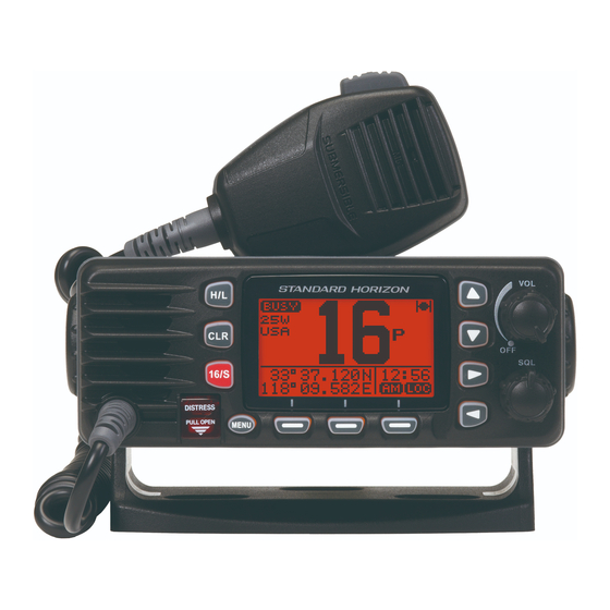
Affordable compact class D fixed mount VHF radio
Submersible IPX8 class (4.92 feet for 30 minutes)
Meets ITU-R M493-13 class D DSC (Digital Selective Calling)
Built in Separate Receiver for CH70 (Receiving DSC Calls)
Programmable soft keys
Easy to Operate Icon/Menu System
Oversized Full dot matrix display (31 mm x 55 mm)
GPS position and time shown* on a full dot matrix display
DSC distress, individual, group, all ships, position request, position
report and DSC test call
Programmable scan, priority scan, and Multi Watch (Dual Watch or
Triple Watch)
NMEA in and output connections to a compatible GPS chart plotter
All USA/International and Canadian marine channels
Preset Key used to recall up to 10 favorite channels
Automaticarry poll the GPS position of up to 6 ships using DSC
NOAA weather channel selection with Weather Alert
GX1300
ECLIPSE GX1300
Class D DSC Marine Transceiver
Owner's Manual
* When GPS connected
25 Watt VHF/FM
Page 1
Advertisement
Table of Contents

Related Manuals for Standard Horizon Eclipse GX1300


Summary of Contents for Standard Horizon Eclipse GX1300
- Page 1 ECLIPSE GX1300 25 Watt VHF/FM Class D DSC Marine Transceiver Owner's Manual Affordable compact class D fixed mount VHF radio Submersible IPX8 class (4.92 feet for 30 minutes) Meets ITU-R M493-13 class D DSC (Digital Selective Calling) Built in Separate Receiver for CH70 (Receiving DSC Calls) ...
-
Page 2: Table Of Contents
TABLE OF CONTENTS Quick Reference Guide ....................5 1 GENERAL INFORMATION ..................6 2 PACKING LIST ......................7 3 OPTIONS .........................7 4 ONLINE WARRANTY REGISTRATION(in USA or Canada only) ......7 5 GETTING STARTED ....................8 5.1 ABOUT VHF RADIO ..................8 5.2 SELECTING AN ANTENNA ................8 5.2.1 Coaxial Cable ..................9 5.3 EMERGENCY ( CHANNEL 16 USE ) ..............10 5.4 CALLING ANOTHER VESSEL ( CHANNEL 16 OR 9 ) ........10... - Page 3 TABLE OF CONTENTS 9 DIGITAL SELECTIVE CALLING ................36 9.1 GENERAL ......................36 9.2 MARITIME MOBILE SERVICE IDENTITY ( MMSI ) ........36 9.2.1 What is an MMSI? ................36 9.2.2 Programming the MMSI ..............37 9.3 DSC DISTRESS ALERT ................38 9.3.1 Transmitting a DSC Distress Alert .............38 9.3.2 Receiving a DSC Distress Alert ............42 9.4 ALL SHIPS CALL ...................43 9.4.1 Transmitting an All Ships Call ............43...
- Page 4 TABLE OF CONTENTS 10 SETUP MENU ......................87 10.1 CONFIGURATION SETUP ................87 10.1.1 Lamp Adjustment ................87 10.1.2 LCD Contrast ...................87 10.1.3 Key Beep ..................88 10.1.4 Location Format ................89 10.1.5 Time Offset ..................89 10.1.6 Time Display ..................89 10.1.7 Time Format ..................89 10.1.8 Unit Of Measure ................90 10.1.9 Soft Keys ..................91 10.2 CHANNEL SETUP ..................93 10.2.1 Channel Group (Band Selection) .............93...
-
Page 5: Quick Reference Guide
uick efeRence uide Rotate the VOL knob clockwise until it clicks to turn on the radio. Rotate the VOL knob to adjust the speaker audio volume. Press the ▲ or ▼ key on the radio to select the operating channel. ... -
Page 6: General Information
1 GENERAL INFORMATION The GX1300 ECLIPSE is a marine VHF transceiver designed for use in the frequency range of 156.025 to 163.275 MHz. The GX1300 can be operated from 11 to 16 VDC and has a switchable RF output power of 1 watt or 25 watts. -
Page 7: Packing List
PRODUCT SUPPORT INQUIRIES If you have any questions or comments regarding the use of the GX1300, you can visit the STANDARD HORIZON website to send an E-Mail or contact the Product Support team at (800) 767-2450 M-F 8:00-5:00 PST. GX1300... -
Page 8: Getting Started
5 GETTING STARTED 5.1 ABOUT VHF RADIO The radio frequencies used in the VHF marine band lie between 156 and 158 MHz with some shore stations available between 161 and 163 MHz. The marine VHF band provides communications over distances that are essen- tially “line of sight”... -
Page 9: Coaxial Cable
5.2.1 Coaxial Cable VHF antennas are connected to the transceiver by means of a coaxial cable – a shielded transmission line. Coaxial cable is specified by its diameter and construction. For runs less than 20 feet (6 m), RG-58/U (about 0.25" (6 mm) in diameter), is a good choice. -
Page 10: Emergency ( Channel 16 Use )
5.3 EMERGENCY ( CHANNEL 16 USE ) Channel 16 is known as the Hail and Distress Channel. An emergency is defined as a threat to life or property. In such instances, be sure the trans- ceiver is on and set to CHANNEL 16. Then use the following procedure: 1. -
Page 11: Operating On Channels 13 And 67 (Usa Channel Group Only)
not exceed 30 seconds but may be repeated 3 times at 2-minute intervals. Prior to making contact with another vessel, refer to the channel charts in this manual, and select an appropriate channel for communications after initial contact. For example, Channels 68 and 69 are some of the channels avail- able to non-commercial (recreational) boaters. -
Page 12: Installation
6 INSTALLATION 6.1 LOCATION The radio can be mounted at any angle. Choose a mounting location that: • keeps the radio and microphone at least 3 feet (1 m) away from your vessel’s magnetic navigation compass • provides accessibility to the front panel controls •... -
Page 13: Optional Mmb-84 Flush Mount Bracket
6.2.2 Optional MMB-84 Flush Mount Bracket 1. To assist in flush mounting, a template has been included. Use this template to assess the mounting location. 2. Use the template to mark the location where the rectangular hole is to be cut. Confirm the space behind the dash or panel is deep enough to accommodate the transceiver (at least 5.5"... -
Page 14: Electrical Connections
6.3 ELECTRICAL CONNECTIONS CAUTION Reverse polarity connections will damage the radio! Connect the power cord and antenna to the radio. Antenna and Power Supply connections are as follows (see Figure 1): 1. Mount the antenna at least 3.28 feet (1 m) away from the radio. At the rear of the radio, connect the antenna cable. -
Page 15: Fuse Replacement
Fuse Replacement To take out the fuse from the fuse holder, hold both ends of the fuse holder and pull the fuse holder apart, do not bend the fuse holder. When you replace the fuse, please confirm that the fuse is tightly fixed on the metal contact located inside the fuse Holder. -
Page 16: Accessory Cable
6.4 ACCESSORY CABLE When connecting the external speaker or GPS navigation receiver, strip off about 1" (2.5 cm) of the specified wire’s insulation, then splice the ends together using proper waterproofing techniques. Wire Color/Description Connection Examples WHITE - External Speaker ( + ) Connect to external 4-ohm audio speaker SHIELD - External Speaker (–) Connect to external 4-ohm audio speaker YELLOW - NMEA GPS Input ( + ) -
Page 17: Checking Gps Connections
6.5 CHECKING GPS CONNECTIONS After connections have been made between the BUSY GX1300 and the GPS, a small satellite icon will appear on the top right corner of the display, and displays your current location (Latitude/Longitude) 23˚56.890N 09:56 123˚56.890W on the display . NOTE •... -
Page 18: Changing The Gps Time
6.6 CHANGING THE GPS TIME From the factory the GX1300 displays GPS satellite time or UTC (Universal Time Coordinated or GMT (Greenwich Mean Time)) time. A time offset is needed to show the local time in your area. 1. Press the MENU key to display the menu. 2. -
Page 19: Changing The Time Location
6.7 CHANGING THE TIME LOCATION This menu item allows you to choose to show UTC or the local time which is selected in Section 6.6. 1. Press the MENU key to display the menu. 2. Select “ SETUP ” with the ▲ / ▼ / ◄ / ► keys, SELECT then press the soft key. -
Page 20: Changing The Time Format
6.8 CHANGING THE TIME FORMAT This menu item allows you to choose to show time in 12-hour or 24-hour format. 1. Press the MENU key to display the menu. 2. Select “ SETUP ” with the ▲ / ▼ / ◄ / ► keys, SELECT then press the soft key. -
Page 21: Controls And Indicators
7 CONTROLS AND INDICATORS BUSY 23˚56.890N 09:56 123˚56.890W DISTRESS PULL OPEN 7.1 FRONT PANEL Power Switch / Volume Control Knob ( VOL ) Turns the transceiver on and off as well as adjusts the audio volume. Rotate this knob clockwise to turn the radio on and to increase the speaker audio volume level. - Page 22 Soft Keys The 3 programmable soft keys can be customized by the SETUP menu (see the section “10.1.7 SOFT KEYS”). When one of the soft keys is pressed briefly, the functions will appear above each key on the display. CH/WX SCAN SCAN MEM...
-
Page 23: Rear Panel
7.2 REAR PANEL DC Input Cable Connects the radio to a DC power supply capable of delivering 12V DC. External Speaker Connection Cable Connects the GX1300 to an external speaker. GPS Receiver Connection Cable Connects the GX1300 to a GPS receiver. -
Page 24: Microphone
7.3 MICROPHONE PTT (Push-To-Talk) Switch Keys the transmitter when the transceiver is in radio mode. MIC (Microphone) Hole Transmits the voice message with reduction of background noise, using Clear Voice Noise Reduction Technology. NOTE Be sure your mouth is about 1" (1.3 cm) from the MIC hole for best performance. -
Page 25: Basic Operation
8 BASIC OPERATION 8.1 RECEPTION 1. After the GX1300 has been installed, ensure that the power supply and antenna are properly connected. 2. Turn the VOL knob clockwise until it clicks to turn the transceiver on. 3. Turn the SQL knob fully counterclockwise. This state is known as “squelch off”. -
Page 26: Simplex/Duplex Channel Use
8.4 SIMPLEX/DUPLEX CHANNEL USE Refer to the VHF MARINE CHANNEL CHART (page 104) for instructions on use of simplex and duplex channels. NOTE All channels are factory-programmed in accordance with International, Industry Canada (Canada), and FCC (USA) regulations. Mode of op- eration cannot be altered from simplex to duplex or vice-versa. -
Page 27: Noaa Weather Channels
8.6 NOAA WEATHER CHANNELS 1. To receive a NOAA weather channel, press one of the soft keys, then press the soft key from any channel. The transceiver will go to the last selected weather channel and the “WX” icon appears on the display. 2. -
Page 28: Scanning
8.7 SCANNING Allows the user to select the scan type from Memory scan or Priority scan. “Memory scan” scans the channels that were programmed into memory. “Priority scan” scans the channels programmed in memory with the priority channel. 8.7.1 Selecting the Scan Type 1. -
Page 29: Scan Memory Programming
8.7.2 Scan Memory Programming 1. Press the MENU key to display the menu. 2. Select “ SETUP ” with the ▲ / ▼ / ◄ / ► keys, SELECT then press the soft key. 3. Press the ▲ / ▼key to select “ C H A N N E L BACK SELECT SETUP ”, then press the... -
Page 30: Priority Channel Setting
8.7.4 Priority Channel Setting In the default setting, Channel 16 is set as the priority channel. You may change the priority channel to another channel from Channel 16 via the SETUP menu. 1. Press the MENU key to display the menu. 2. -
Page 31: Multi Watch (To Priority Channel)
8.8 MULTI WATCH (TO PRIORITY CHANNEL) Multi watch is used to scan two or three channels for communications. In Dual Watch, a normal VHF channel and the priority channel are scanned alternately. In Triple Watch, a normal VHF channel, the priority channel, and the sub ... -
Page 32: Starting The Dual Watch
8.8.2 Starting the Dual Watch 1. Adjust the SQL knob until the background noise disappears. 2. Select the channel you wish to dual watch to the priority channel. 3. Press one of the soft keys, then press the BUSY soft key (it may be necessary to press the ◄ / P-SET ►... -
Page 33: Preset Channels: Instant Access
8.9 PRESET CHANNELS: INSTANT ACCESS 10 preset channels can be programmed for instant access. Pressing the PRESET PRESET soft key activates the preset channel bank. If the soft key is pressed and no channels have been assigned, an alert beep will be emitted from the speaker. -
Page 34: Deleting A Preset Channel
8.9.3 Deleting a Preset Channel 1. Press one of the soft keys, then press the BUSY PRESET soft key. P-SET 2. Press the ▲ / ▼ key to select the preset channel to be deleted. 3. Press one of the soft keys, then press and PRESET hold the soft key until the channel... -
Page 35: Operation Menu
8.10 OPERATION MENU The GX1300 provides advanced features below, via the menu screen displayed by pressing the MENU key on the front panel. BACK SELECT The following seven types of DSC (Digital Selective Calling) are available: Individual, Group, All Ships, Position Request, Position Report, Polling, and Auto Position Polling. -
Page 36: Digital Selective Calling
9 DIGITAL SELECTIVE CALLING 9.1 GENERAL WARNING The GX1300 is designed to generate digital maritime distress and safety calls to facilitate search and rescue. To be effective as a safety device, this equipment must be used only within communication range of a shore-based VHF marine channel 70 distress and safety watch system. -
Page 37: Programming The Mmsi
9.2.2 Programming the MMSI WARNING The MMSI can be input only once. Therefore, please be careful not to input the incorrect MMSI number. If you need to change the MMSI number after it has been entered, the radio will have to be re- turned to Factory Service. -
Page 38: Dsc Distress Alert
9.3 DSC DISTRESS ALERT The GX1300 is capable of transmitting and receiving DSC distress messag- es to all DSC radios. The GX1300 may be connected to a GPS to also trans- mit the latitude and longitude of the vessel. NOTE If a GPS with NMEA output is not connected to the radio, the GX1300 will beep 10 minutes after the radio is turned on and will continue to beep every 4 hours alerting to connect a GPS. - Page 39 4. When a DSC distress acknowledgment is !!DISTRESS!! RX ACKNOWLEDGED received on channel 70, a DSC distress alarm USCG CA sounds and channel 16 is automatically select- SINCE: 00:15 ed. Pick up the microphone and press and hold the PTT switch to advise your distress situation.
- Page 40 NATURE 4. Press the soft key. DIST ALERT MSG UNDESIGNATED 5. Press the ▲ / ▼ keys to select the desired POS: --°--.--- - nature of distress category, then press the ---°--.--- - TIME: --:--UTC SELECT soft key. BACK NATURE POS/TM 6.
- Page 41 Pausing a DSC Distress Alert After a DSC distress call is transmitted, it is repeated every 4 minutes until the call is canceled by the user or until the radio is turned off and on again. The GX1300 has provision to suspend (pause) the re-transmitting of the distress call by the procedure below.
-
Page 42: Receiving A Dsc Distress Alert
9.3.2 Receiving a DSC Distress Alert 1. When a DSC distress alert is received, an emergency alarm sounds. The display will show the MMSI (or name) of the vessel transmitting the distress. 2. Press any key on the radio to stop the alarm. 3. -
Page 43: All Ships Call
9.4 ALL SHIPS CALL The all ships call function allows contact to be established with DSC equipped vessels without having their MMSI in the individual calling direc- tory. Also, priority for the call can be designated as "urgency" or "safety". URGENCY Call: This type of call is used when a vessel may not truly be in distress, but has a potential problem that may lead to a distress situation. -
Page 44: Receiving An All Ships Call
7. After the all ships call is transmitted, the trans- ALL SHIPS ceiver will switch to the channel which select- CATEG: SAFETY ed on the step 5 above, with no change of the SINCE: 00:05 [ Transmitted ] QUIT display. To change the display, press the QUIT soft key. -
Page 45: Setting Up The All Ships Call Ringer
9.4.3 Setting up the All Ships Call Ringer The GX1300 has the capability to turn off the all ships call ringer. 1. Press the MENU key to display the menu. 2. Press the ▲ / ▼ keys to select “ SETUP ”, then SELECT press the soft key. -
Page 46: Individual Call
9.5 INDIVIDUAL CALL This feature allows the GX1300 to contact another vessel with a DSC VHF radio and automatically switch the receiving radio to a desired communica- tions channel. This feature is similar to calling a vessel on CH16 and request- ing to go to another channel (switching to the channel is private between the two stations). - Page 47 7. Press the ▲ / ▼ keys to scroll to the first letter NAME: of the name of the vessel or person you want ----------- to list in the directory. SELECT 8. Press the soft key to store the first BACK FINISH SELECT...
-
Page 48: Setting Up Individual Call Reply
9.5.2 Setting up Individual Call Reply Allows setting up the radio to automatically (default setting) or manually respond to a DSC individual call requesting you to switch to a working channel for voice communications. When the manual response is selected the MMSI of the calling vessel is shown allowing you to see who is calling. -
Page 49: Setting Up The Individual Call Acknowledge Message
9.5.3 Setting up the Individual Call Acknowledge Message The GX1300 can select either reply message “Able” (default) or “Unable” when the individual reply setting (described previous section) is set to “AUTO”. 1. Press the MENU key to display the menu. 2. -
Page 50: Transmitting An Individual Call
9.5.4 Transmitting an Individual Call This feature allows you to contact another vessel, switch their radio to a requested working channel and ring like a telephone. This feature is similar to calling a vessel on CH16 and requesting to go to another channel. Individual Call from Individual / Position Call Directory 1. - Page 51 9. When the GX1300 receives an acknowledgement from the vessel you called, the radio will automatically switch to the operating channel select- ed in step 6 and produce a ringing sound. 10. Key the microphone and call the other vessel you desire to communi- cate with.
-
Page 52: Receiving An Individual Call
10. Press the soft key to transmit the individu- INDIVIDUAL 366901555 al DSC signal. CATEG: ROUTINE CH: 08 Transmit a Call? 11. After an individual call is transmitted, if the reply signal is not received, “ Waiting for ACK ” is shown on the display which means the GX1300 is waiting for the vessel you called to send an acknowledgement. - Page 53 ACCEPT 3. Press the soft key to accept the call. RX INDIVIDUAL YAESU CATEG: ROUTINE CH: 08 SINCE: 00:05 ACCEPT PAUSE QUIT P A U S E 4. Press the soft key to suspend the BUSY acknowledgement. R E S U M E Press the soft key to resume the acknowledgement.
-
Page 54: Setting Up The Individual Call Ringer
9.5.6 Setting up the Individual Call Ringer When an individual call is received the radio will produce a ringing tone for 2 minutes (by default). This selection allows the individual call ringer time to be changed. 1. Press the MENU key to display the menu. 2. - Page 55 The GX1300 has the capability to turn off the individual call ringer. 1. Press the MENU key to display the menu. 2. Press the ▲ / ▼ keys to select “ SETUP ”, then SELECT press the soft key. 3. Press the ▲ / ▼ keys to select “ DSC SETUP ”, BACK SELECT SELECT...
-
Page 56: Group Call
MMSI numbers. The first digit of a group MMSI is always set to “0” by the international rules. All Standard Horizon radios are preset so when programming a group MMSI the first digit is set to “0”. - Page 57 1. Press the MENU key to display the menu. 2. Press the ▲ / ▼ keys to select “ SETUP ”, then SELECT press the soft key. 3. Press the ▲ / ▼ keys to select “ DSC SETUP ”, BACK SELECT SELECT...
-
Page 58: Transmitting A Group Call
11. Select “ GROUP MMSI ” with the ▲ / ▼ keys, NAME: SELECT then press the soft key. YAESU - GP ---- GROUP MMSI: 0-------- BACK FINISH SELECT 12. Press the ▲ / ▼ keys to scroll through GROUP MMSI: numbers, 0 to 9. - Page 59 5. Press the ▲ / ▼ keys to select a group you HISTORY YAESU GP SELECT want to contact, then press the soft USCG GP key. MEMORY SHIPS HORIZON GP BACK SELECT 6. Press the ▲ / ▼ keys to select the operat- INTERSHIP CH CH:06 ing channel you want to communicate on and...
- Page 60 5. P r e s s t h e ▲ / ▼ k e y s to scroll through NEW ID GROUP MMSI: numbers, 0 to 9. 03--------- SELECT 6. Press the soft key to store the number and step to the next digit to the right. BACK FINISH SELECT...
-
Page 61: Receiving A Group Call
9.6.3 Receiving a Group Call 1. When a group call is received, the GX1300 will produce a ringing alarm sound. (DSC BEEP needs to be enabled to hear alarm.) The display will show the MMSI (or name) of the vessel transmitting the group call. -
Page 62: Setting Up The Group Call Ringer
9.6.4 Setting up the Group Call Ringer The GX1300 has the capability to turn off the group call ringer. 1. Press the MENU key to display the menu. 2. Press the ▲ / ▼ keys to select “ SETUP ”, then SELECT press the soft key. -
Page 63: Position Request
GX1300. Standard Horizon has taken this feature one step further, if any Standard Horizon GPS is connected to the GX1300, the polled position of the vessel is shown on the display of the GPS chart plotter making it easy to navigate to the location of the polled vessel. - Page 64 6. Press the soft key to transmit the position POS REQUEST YAESU request call. CATEG: SAFETY Transmit a Call? 7. If the GX1300 does not receive a reply, the POS REQUEST YAESU display will be as shown in the illustration on CATEG: SAFETY RESEND the right.
- Page 65 Position Request - Manual MMSI Entry You may enter an MMSI number manually to contact a vessel without storing the MMSI in the individual/position call directory. 1. Press the MENU key to display the menu. 2. Press the ▲ / ▼ keys to select “ DSC ”, then SELECT press the soft key.
-
Page 66: Receiving A Position Request
11. When the GX1300 receives the position from the polled vessel, the GX1300 will produce a ringing alarm sound and the position from the polled vessel is sent to a GPS chart plotter via NMEA 0183. (DSC BEEP needs to be enabled to hear alarm.) Press any key to stop the alarm. -
Page 67: Setting Up The Position Request Ringer
9.7.3 Setting up the Position Request Ringer The GX1300 has the capability to turn off the position request ringer. 1. Press the MENU key to display the menu. 2. Press the ▲ / ▼ keys to select “ SETUP ”, then SELECT press the soft key. -
Page 68: Position Report
9.8 POSITION REPORT The feature is similar to the position request, however instead of requesting a position of another vessel this function allows you to send your position to another vessel. In order to send your position you need to have a GPS receiver connected or to have manually input your position. - Page 69 Position Report - Manual MMSI Entry You may enter an MMSI number manually to contact a vessel without storing the MMSI in the individual/position call directory. 1. Press the MENU key to display the menu. 2. Press the ▲ / ▼ keys to select “ DSC ”, then SELECT press the soft key.
-
Page 70: Receiving A Dsc Position Report Call
9.8.2 Receiving a DSC Position Report Call When another vessel transmits their location to the GX1300 the following will happen: 1. When the position report call is received, a ringing sound will be produced and the display shows the vessels MMSI or name, how long since the call was received and the GPS position of the vessel. -
Page 71: Setting Up A Position Report Ringer
9.8.5 Setting up a Position Report Ringer The GX1300 has the capability to turn off the position report ringer. 1. Press the MENU key to display the menu. 2. Press the ▲ / ▼ keys to select “ SETUP ”, then SELECT press the soft key. -
Page 72: Manual Input Of The Gps Location ( Lat/Lon )
9.9 MANUAL INPUT OF THE GPS LOCATION ( LAT/LON ) You may send the latitude and longitude of your vessel manually when a GPS receiver is not connected or is not functioning. After the position is entered, transmitting a DSC distress or position report will contain the manually entered position. -
Page 73: Auto Pos Polling
9.10 AUTO POS POLLING The GX1300 has the capability to automatically track four stations programmed into the individual directory. 9.10.1 Setting up the Polling Call Type 1. Press the MENU key to display the menu. 2. Press the ▲ / ▼ keys to select “ SETUP ”, then SELECT press the soft key. -
Page 74: Selecting Stations To Be Automatically Polled
4. Select “ AUTO POS TIME ” with the ▲ / ▼ keys, DSC SETUP AUTO POS POLL SELECT then press the soft key. AUTO POS TIME CH SWITCH TIMER DSC BEEP BACK SELECT 5. Press the ▲ / ▼ keys to select the desired AUTO POS TIME 30 sec ENTER... -
Page 75: Enabling/Disabling Auto Pos Polling
7. Repeat steps 5 and 6 for all the desired SELECT ID 1:HORIZON individual to be polled. 2:MEMORY SHIPS 3:USCG-2 4:YAESU-1 BACK SELECT BACK soft key to return to “ AUTO POS POLLING ”. 8. Press the 9.10.4 Enabling/Disabling Auto POS Polling 1. -
Page 76: Dsc Test Call
9.11 DSC TEST CALL This function is used to contact another DSC equipped vessel to ensure the DSC functions of the radio are operating correctly. 9.11.1 Transmitting a DSC Test Call DSC Test Call from Individual / Position Call Directory 1. - Page 77 DSC Test Call - Manual MMSI Entry 1. Press the MENU key to display the menu. 2. Press the ▲ / ▼ keys to select “ DSC ”, then SELECT press the soft key. 3. Press the ▲ / ▼ keys to select “ TEST CALL ”, BACK SELECT S E L E C T...
-
Page 78: Receiving A Dsc Test Call
9.11.2 Receiving a DSC Test Call When another vessel transmits a DSC test call RX TEST CALL YAESU to the GX1300, the radio automatically reply an DSC TEST REPLY acknowledgement. The display shows the MMSI SINCE: 00:05 Transmitted or the name of the vessel transmitting the DSC QUIT test call. -
Page 79: Polling Call
9.12 POLLING CALL The GX1300 has the capability to track another vessel. 9.12.1 Transmitting a Polling Call Position Polling from Individual / Position Call Directory 1. Press the MENU key to display the menu. 2. Press the ▲ / ▼ keys to select “ DSC ”, then SELECT press the soft key. - Page 80 Position Polling - Manual MMSI Entry 1. Press the MENU key to display the menu. 2. Press the ▲ / ▼ keys to select “ DSC ”, then SELECT press the soft key. 3. Press the ▲ / ▼ keys to select “ P O L L I N G BACK SELECT CALL ”, and then press the...
-
Page 81: Receiving A Polling Call
9.12.2 Receiving a Polling Call When another vessel transmits a polling call to the RX POLLING CALL YAESU GX1300, the radio automatically reply an acknowl- POLLING REPLY edgement. The display shows the MMSI or the SINCE: 00:05 Transmitted name of the vessel transmitting the polling call. QUIT QUIT Press the... -
Page 82: Dsc Log Operation
9.13 DSC LOG OPERATION The GX1300 logs transmitted DSC calls, received distress calls, and other calls (individual, group, all ships, etc.). The DSC log feature is similar to an answer machine where calls are recorded for review and a “ ”... -
Page 83: Reviewing A Logged Dsc Distress Call
6. Press the ▲ / ▼ key to scroll the display. TRANSMITTED LOG INDIVIDUAL 123456789 YAESU TX TM: 12:56 UTC BACK DELETE TRANSMITTED LOG DATE: 12/JAN CATER: ROUTINE CH: 06 [ Delayed ACK ] BACK DELETE BACK 7. Press the soft key to go back to the DSC transmitted call list. -
Page 84: Reviewing A Logged Other Calls
6. Press the ▲ / ▼ key to scroll the display. DISTRESS LOG 123456789 YAESU RX TM: 12:56 UTC DATE: 12/JAN BACK DELETE DISTRESS LOG DATE: 12/JAN CATER: ROUTINE CH: 06 [ Delayed ACK ] BACK DELETE BACK 7. Press the soft key to go back to the DSC distress call list. -
Page 85: Deleting Calls From The "Dsc Log" Directory
6. Press the ▲ / ▼ key to scroll the display. RX OTHER LOG INDIVIDUAL 123456789 YAESU RX TM: 12:56 UTC BACK DELETE RX OTHER LOG DATE: 12/JAN CATER: ROUTINE CH: 06 [ Delayed ACK ] BACK DELETE BACK 7. Press the soft key to go back to the DSC other call list. - Page 86 7. Press the soft key to go back to the catego- LOG DELETE TRANSMITTED LOG ry list. Complete NOTE The procedure above will delete logged calls of the selected category all at once. To delete logged calls one by one, review details of a call you want to DELETE delete, then press the soft key.
-
Page 87: Setup Menu
10 SETUP MENU 10.1 CONFIGURATION SETUP 10.1.1 Lamp Adjustment Allows adjustment of the backlight intensity or to turn it off. 1. Press the MENU key to display the menu. 2. Press the ▲ / ▼ keys to select “ SETUP ”, then SELECT press the soft key. -
Page 88: Key Beep
4. Select “ CONTRAST ” with the ▲ / ▼ keys, then CONFIGURATION DIMMER SELECT press the soft key. CONTRAST KEY BEEP LOCATION FORMT BACK SELECT 5. Press the ▲ / ▼ keys to select the desired CONTRAST level. The contrast level can be set from “ 00 ” to “... -
Page 89: Location Format
10.1.4 Location Format This selection sets the coordinate system to be shown on the LCD. 1. Press the MENU key to display the menu. 2. Press the ▲ / ▼ keys to select “ SETUP ”, then SELECT press the soft key. -
Page 90: Unit Of Measure
10.1.8 Unit Of Measure This selection sets the distance units. 1. Press the MENU key to display the menu. 2. Press the ▲ / ▼ keys to select “ SETUP ”, then SELECT press the soft key. 3. Press the ▲ / ▼ keys to select “ CONFIGURA- BACK SELECT TION ”, then press the... -
Page 91: Soft Keys
10.1.9 Soft Keys This menu item assigns the number of soft keys, soft key selection and how long the display will show the soft key icon after a soft key is pressed. Assigning Soft Keys 1. Press the MENU key to display the menu. 2. - Page 92 Available functions are: DISPLAY FUNCTION WX/CH Switches channels between weather and marine. SCAN Starts and stops scanning. DW/TW Starts and stops the dual or triple watch scan. SCAN MEMORY Switches on and off of the memory channel scan. PRESET Saves or deletes the preset memory channel. GPS STATUS GPS status display Selecting How Long the Soft Keys are Shown...
-
Page 93: Channel Setup
10.2 CHANNEL SETUP 10.2.1 Channel Group (Band Selection) This selection allows you to change the channel group from International to USA or Canada. Refer to section “8.5 INTERNATIONAL, USA, AND CANADA MODE” for details. 10.2.2 Weather Alert This selection is used to enable or disable the NOAA Weather Alert function. 1. -
Page 94: Scan Type
10.2.5 Scan Type This selection is used to select the scan mode between “Memory Scan” and “Priority Scan”. Refer to section “8.7.1 Selecting the Scan Type” for details. 10.2.6 Scan Resume This selection is used to select the time the GX1300 waits after a transmis- sion ends before the radio start to scan channels again. - Page 95 1. Press the MENU key to display the menu. 2. Select “ SETUP ” with the ▲ / ▼ / ◄ / ► keys, SELECT then press the soft key. 3. Press the ▲ / ▼key to select “ C H A N N E L BACK SELECT SETUP ”, then press the...
-
Page 96: Dsc Setup
10.3 DSC SETUP 10.3.1 Individual Directory The GX1300 has a DSC directory that allows you to store a vessel or person’s name and the MMSI number associated with vessels you wish to transmit individual calls, position requests and position report transmissions. To transmit an individual call you must program this directory with information of the persons you wish to call, similar to a cellular phones telephone direc- tory. -
Page 97: Group Directory
10.3.5 Group Directory For this function to operate, the same group MMSI must be programmed into all the DSC VHF radios within the group of vessels that will be using this feature. To understand group MMSI programming, first a ship MMSI has to be understood. -
Page 98: Auto Channel Switching Time
10.3.8 Auto Channel Switching Time When a DSC distress call or an all ships call (urgency or safety) is received, the GX1300 will automatically switch to the channel 16. This menu selection allows the automatic switching time to be changed. 1. -
Page 99: Maintenance
Ensure that the supply voltage to the transceiver does not exceed 16 VDC or fall below 11 VDC. • Use only STANDARD HORIZON-approved accessories and replacement parts. In the unlikely event of serious problems, please contact your Dealer or our repair facility. -
Page 100: Troubleshooting Chart
11.3 TROUBLESHOOTING CHART SYMPTOM PROBABLE CAUSE REMEDY Transceiver fails to No DC voltage to the a. Check the 12 VDC battery connections and power up. transceiver, or blown the fuse. fuse. b. The VOL knob needs to be rotated clock- wise to turn the radio on. -
Page 101: Channel Assignments
12 CHANNEL ASSIGNMENTS Tables on the following columns list the VHF Marine Channel assignments for U.S.A. and International use. Below are listed some data about the charts. 1. VTS. Where indicated, these channels are part of the U.S. Coast Guard’s Vessel Traffic System. - Page 102 6. Marine vessels equipped with VHF radios are required to monitor Channel 16. 7. 156.050 MHz and 156.175 MHz are available for port operations and commercial communications purposes when used only within the U.S. Coast Guard designated Vessel Traffic Services (VTS) area of New Orleans, on the lower Mississippi River from the various pass entrances in the Gulf of Mexico to Devil’s Swamp Light at River Mile 242.4 above head of passes near Baton Rouge.
- Page 103 12. Use of 156.375 MHz is available for navigational communications only in the Mississippi River from South Pass Lighted Whistle Buoy “2” and Southwest Pass entrance Mid channel Lighted Whistle Buoy to mile 242.4 above head of Passes near Baton Rouge, and in addition over the full length of the Mississippi River-Gulf Outlet Canal from entrance to its junction with the Inner Harbor Navigation Canal, and over the full length of the Inner Harbor Navigation Canal from its junction with the Mississippi...
-
Page 104: Vhf Marine Channel Chart
VHF MARINE CHANNEL CHART CHANNEL USE 156.050 160.650 Public Correspondence (Marine Operator) 156.050 Port Operation and Commercial. VTS in selected areas 156.100 160.700 Public Correspondence (Marine Operator) 156.150 160.750 Public Correspondence (Marine Operator) 156.150 U.S. Government Only, Coast Guard 156.200 160.800 Public Correspondence (Marine Operator), Port operation, ship movement 156.200 Pacific coast: Coast Guard, East Coast:... - Page 105 VHF MARINE CHANNEL CHART CHANNEL USE 156.025 160.625 Public Correspondence (Marine Operator) 156.075 160.675 Public Correspondence (Marine Operator), Port operation, ship movement 156.075 Public Coast: Coast Guard; East Coast: commercial fishing only 156.125 160.725 Public Correspondence (Marine Operator), Port operation, ship movement 156.125 Public Coast: Coast Guard;...
- Page 106 VHF MARINE CHANNEL CHART CHANNEL USE 157.025 161.625 Port operation, ship movement 157.025 Commercial 157.075 161.675 Port operation, ship movement 157.075 U.S. Government Only - Environmental protection operations 157.075 Canadian Coast Guard Only 157.125 161.725 Public Correspondence (Marine Operator), Port operation, ship movement 157.125 U.S.
-
Page 107: Warranty
United States and Canada. For limited Warranty details outside the United States, contact the dealer in your country. STANDARD HORIZON (a division of YAESU U.S.A.) warrants, to the origi- nal purchaser only, each new Marine Communications Product (“Product”) - Page 108 Product or part(s) therein which, upon examination by STANDARD HORIZON, appear to be defective or not up to factory specifications. STANDARD HORIZON may, at its option, repair or replace parts or subas- semblies with new or reconditioned parts and subassemblies. Parts thus repaired or replaced are warranted for the balance of the original applicable warranty.
- Page 109 STANDARD HORIZON. IN CONNECTION WITH THE SALE OF ITS PRODUCTS, STANDARD HORIZON MAKES NO WARRAN- TIES, EXPRESS OR IMPLIED AS TO THE MERCHANTABILITY OR FITNESS FOR A PARTICULAR PURPOSE OR OTHERWISE, EXCEPT AS EXPRESSLY SET FORTH HEREIN.
- Page 110 STANDARD HORIZON. Lifetime Flat Rate Service Program: For the original Owner only, for the lifetime of the unit, STANDARD HORIZON will repair the unit to original specifications. Note: The flat rate amount is payable by the Owner only if STAN- DARD HORIZON or the STANDARD HORIZON Dealer determines that a repair is needed.
-
Page 111: Specifications
14 SPECIFICATIONS Performance specifications are nominal, unless otherwise indicated, and are subject to change without notice. 14.1 GENERAL Channels ..........All USA, International and Canadian Input Voltage................13.8 VDC ±20% Current Drain Standby ....................0.3 A Receive ....................1.0 A Transmit ...............5.5 A (Hi);... -
Page 112: Receiver
14.3 RECEIVER Frequency Range ............156.050 to 162.000 MHz Sensitivity 20 dB SINAD ..................0.3 µV 20 dB SINAD (70 CH Receiver) ............0.3 µV Squelch Sensitivity (Threshold) ............0.25 µV Modulation Acceptance Bandwidth.............±7.5 kHz Selectivity Spurious and Image Rejection ............–75 dB Intermodulation and Rejection at 12 dB SINAD ...... -
Page 113: Gx1300 Dimensions
14.4 GX1300 DIMENSIONS 6.63 168.4 5.08 4.96 126 6.10 GX1300 Page 113... -
Page 114: Fcc Radio License Information
15 FCC RADIO LICENSE INFORMATION Standard Horizon radios comply with the Federal Communication Commis- sion (FCC) requirements that regulate the Maritime Radio Service. 15.1 STATION LICENSE An FCC ship station license is no longer required for any vessel traveling in U.S. -
Page 115: Fcc Notice
NOTICE Unauthorized changes or modifications to this equipment may void compliance with FCC Rules. Any change or modification must be ap- proved in writing by STANDARD HORIZON. NOTICE This equipment has been tested and found to comply with the limits for a Class B digital device, pursuant to Part 15 of the FCC Rules. -
Page 116: Rf Exposure Safety Statement
17 RF EXPOSURE SAFETY STATEMENT SAFETY INFORMATION Your wireless handheld portable transceiver contains a low power transmit- ter. When the Push-to-Talk (PTT) button is pushed, the transceiver sends out radio frequency (RF) signals. In August 1996, the Federal Communications Commission adopted RF exposure guidelines with safety levels for hand-held wireless devices. - Page 117 MEMO GX1300 Page 117...
- Page 118 MEMO Page 118 GX1300...
- Page 119 THIS DEVICE COMPLIES WITH PART 15 OF THE FCC RULES. OPERATION IS SUBJECT TO THE FOLLOWING TWO CONDITIONS: (1) THIS DEVICE MAY NOT CAUSE HARMFUL INTERFERENCE, AND (2) THIS DEVICE MUST ACCEPT ANY INTERFERENCE RECEIVED, INCLUDING INTERFERENCE THAT MAY CAUSE UNDESIRED OPERATION.
- Page 120 Copyright 2014 YAESU MUSEN CO., LTD. All rights reserved. No portion of this manual YAESU USA may be reproduced without 6125 Phyllis Drive, Cypress, CA 90630, U.S.A. the permission of YAESU MUSEN CO., LTD. Printed in China Page 120 GX1300...
Need help?
Do you have a question about the Eclipse GX1300 and is the answer not in the manual?
Questions and answers
Is there a backup battery internally
The provided context does not mention an internal backup battery for the Standard Horizon Eclipse GX1300.
This answer is automatically generated