Table of Contents
Advertisement
Quick Links
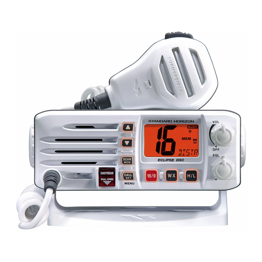
ECLIPSE DSC GX1000S
25 Watt VHF/FM
DSC Marine Transceiver
Owner's Manual
Affordable Ultra Compact Fixed Mount VHF radio
Submersible IPX7 Front Panel
SC-101 DSC (Digital Selective Calling) with Position Report and Request
Programmable Scan, Priority Scan, and Dual Watch
Selectable Channel Names or GPS LAT / LON shown on display
Simple Operation
All USA / International and Canadian Marine Channels
NOAA Weather Channels with Weather Alert
When Attached to GPS Receiver
GX1000S
Page 1
Advertisement
Table of Contents

Related Manuals for Standard Horizon Eclipes DSC GX1000S


Summary of Contents for Standard Horizon Eclipes DSC GX1000S
- Page 1 ECLIPSE DSC GX1000S 25 Watt VHF/FM DSC Marine Transceiver Owner's Manual Affordable Ultra Compact Fixed Mount VHF radio Submersible IPX7 Front Panel SC-101 DSC (Digital Selective Calling) with Position Report and Request Programmable Scan, Priority Scan, and Dual Watch Selectable Channel Names or GPS LAT / LON shown on display Simple Operation All USA / International and Canadian Marine Channels NOAA Weather Channels with Weather Alert...
-
Page 2: Table Of Contents
TABLE OF CONTENTS GENERAL INFORMATION ..................... 4 PACKING LIST ........................4 OPTIONS ..........................4 SAFETY / WARNING INFORMATION ..................5 FCC RADIO LICENSE INFORMATION .................. 6 FCC NOTICE .......................... 7 GETTING STARTED ....................... 8 ABOUT VHF RADIO ....................8 SELECTING AN ANTENNA ..................8 COAXIAL CABLE ....................... - Page 3 TABLE OF CONTENTS 11 DIGITAL SELECTIVE CALLING ..................28 11.1 GENERAL ........................28 11.2 MARITIME MOBILE SERVICE IDENTITY (MMSI) ........... 29 11.2.1 What is an MMSI? ................... 29 11.2.2 Programming the MMSI ................29 11.3 DSC DISTRESS CALL .................... 30 11.3.1 Transmitting a DSC Distress Call ............
-
Page 4: General Information
1 GENERAL INFORMATION The Vertex Standard GX1000S ECLIPSE DSC is a VHF/FM transceiver de- signed for use in the frequency range of 156.025 to 163.275 MHz. The GX1000S ECLIPSE DSC can be operated from 11 to 16 VDC and has a switchable RF output power of 1 watt or 25 watts. -
Page 5: Safety / Warning Information
4 SAFETY / WARNING INFORMATION This radio is restricted to occupational use, work related operations only where the radio operator must have the knowledge to control the exposure condi- tions of its passengers and bystanders by maintaining the minimum separa- tion distance of 0.6 m (2 feet). -
Page 6: Fcc Radio License Information
5 FCC RADIO LICENSE INFORMATION Standard Horizon radios comply with the Federal Communication Commis- sion (FCC) requirements that regulate the Maritime Radio Service. STATION LICENSE An FCC ship station license is no longer required for any vessel traveling in U.S. waters (except Hawaii) which is under 20 meters in length. However, any... -
Page 7: Fcc Notice
6 FCC NOTICE NOTICE Unauthorized changes or modifications to this equipment may void com- pliance with FCC Rules. Any change or modification must be approved in writing by Marine Division of Vertex Standard. NOTICE This equipment has been tested and found to comply with the limits for a Class B digital device, pursuant to Part 15 of the FCC Rules. -
Page 8: Getting Started
7 GETTING STARTED 7.1 ABOUT VHF RADIO The radio frequencies used in the VHF marine band lie between 156 and 158 MHz with some shore stations available between 161 and 163 MHz. The ma- rine VHF band provides communications over distances that are essentially “line of sight”... -
Page 9: Coaxial Cable
7.3 COAXIAL CABLE VHF antennas are connected to the transceiver by means of a coaxial cable – a shielded transmission line. Coaxial cable is specified by it’s diameter and construction. For runs less than 20 feet, RG-58/U, about 1/4 inch in diameter is a good choice. -
Page 10: Installation
8 INSTALLATION 8.1 LOCATION The radio can be mounted at any angle. Choose a mounting location that: • is far enough from any compass to avoid any deviation in compass reading due to the speaker magnet • provides accessibility to the front panel controls •... -
Page 11: Fuse Replacement
1. Mount the antenna at least 3 feet away from the radio. At the rear of the radio, connect the antenna cable. 2. Connect the red power wire to a 13.8 VDC ±20% power source. Connect the black power wire to a negative ground. 3. -
Page 12: Accessory Cable
The NMEA supported sentences are: Input: GLL, GGA, RMC and GNS (RMC sentence is recommended) Output: DSC and DSE (DSC sentences to Standard Horizon Plotter for Position Polling) If you have further inquires, please feel free to contact Product Support at: Phone: (800) 767-2450 Email: marinetech@vxstdusa.com... -
Page 13: Checking Gps Connections
8.4 CHECKING GPS CONNECTIONS After connections have been made between the GX1000S and the GPS, a small satellite icon ( ) will appear on the LCD display. To see the additional GPS information, press and hold the [ H/L ] key. -
Page 14: Changing The Time Location
8.6 CHANGING THE TIME LOCATION Sets the radio to show UTC time or local time with the offset input in section “8.5 CHANGING THE GPS TIME”. 1. Press and hold down the [ CALL ( SET ) MENU ] key until “RADIO SETUP RADIO SETUP”... -
Page 15: Optional Mmb-84 Flush Mount Installation
8.7 OPTIONAL MMB-84 FLUSH MOUNT INSTALLATION 1. To assist in flush mounting, a template has been included. Use this tem- plate to find the mounting location. 2. Use the template to mark the location where the rectangular hole is to be cut. -
Page 16: Controls And Indicators
9 CONTROLS AND INDICATORS NOTE This section defines each control of the transceiver. See Figure 3 for location of controls. For detailed operating instructions refer to section “10 BASIC OPERATION.” POWER SWITCH / VOLUME CONTROL ( VOL ) Turns the transceiver on and off as well as adjusts the speakers audio volume. - Page 17 Figure 3. Controls and Connectors GX1000S Page 17...
- Page 18 [ 16/9 ] Key Immediately recalls channel 16 from any channel location. Holding down this key recalls channel 9. Pressing the [ 16/9 ] key again reverts to the previous selected working channel. Secondary use Press and hold the [ 16/9 ] key then press the [ WX ] key to switch the Chan- nel Group.
- Page 19 EXTERNAL SPEAKER CONNECTION CABLE Connects the GX1000S to a external speaker. GPS RECEIVER CONNECTION CABLE Connects the GX1000S to a GPS receiver. ANTENNA JACK Connects an antenna to the transceiver. Use a marine VHF antenna with an impedance of 50 ohms. PTT ( Push-To-Talk ) SWITCH Keys the transmitter when the transceiver is in radio mode.
-
Page 20: Basic Operation
10 BASIC OPERATION 10.1 RECEPTION 1. After the transceiver has been installed, ensure that the power supply and antenna are properly connected. 2. Turn the VOL knob clockwise to turn on the radio. 3. Turn the SQL knob fully counterclockwise. This state is known as “squelch off”. 4. -
Page 21: Simplex/Duplex Channel Use
10.4 SIMPLEX/DUPLEX CHANNEL USE Refer to the VHF MARINE CHANNEL CHART (page 48) for instructions on use of simplex and duplex channels. NOTE All channels are factory-programmed in accordance with International, Industry Canada (Canada), and FCC (USA) regulations. Mode of op- eration cannot be altered from simplex to duplex or vice-versa. -
Page 22: Noaa Weather Channels
10.6 NOAA WEATHER CHANNELS NOTE NOAA Weather channels are available in the waters of USA and Canada only. 1. To receive a NOAA weather channel, press the [ WX ] key from any chan- nel. The transceiver will go to the last selected weather channel. -
Page 23: Noaa Weather Alert Testing
10.6.2 NOAA Weather Alert Testing NOAA tests the alert system every Wednesday between 11AM and 1PM. To test the GX1000S’s NOAA Weather alert feature, on Wednesday between 11AM and 1PM, setup as in previous section and confirm the alert is heard. 10.7 EMERGENCY ( CHANNEL 16 USE ) Channel 16 is known as the Hail and Distress Channel. -
Page 24: Making Telephone Calls
manual, and select an appropriate channel for communications after initial contact. For example, Channels 68 and 69 are some of the channels available to non-commercial (recreational) boaters. Monitor your desired channel in ad- vance to make sure you will not be interrupting other traffic, and then go back to either channel 16 or 9 for your initial contact. -
Page 25: Scanning
nels. However, in certain situations it may be necessary to temporarily use a higher power. See page 16 ( [ H/L ] key) for means to temporarily override the low-power limit on these two channels. 10.11 SCANNING Allows the user to select the scan type from Memory scan or Priority scan. “Memory scan”... -
Page 26: Priority Scanning (P-Scan)
10.11.3 Priority Scanning ( P-SCAN ) The priority channel is set to channel 16 by the factory default. You may change the priority channel to the desired channel. See box below. 1. Adjust the SQL knob until background noise disappears. 2. -
Page 27: Navigation Indication
10.12 NAVIGATION INDICATION The transceiver has the ability to display the time and the position (Latitude/ Longitude), when connected to a GPS receiver. 1. Press and hold the [ H/L ] key, displays the “Latitude” and “Longitude” information alternately every two seconds. If the GPS receiver is not receiving a fix, “NO POS NO POS”... -
Page 28: Digital Selective Calling
11 DIGITAL SELECTIVE CALLING 11.1 GENERAL WARNING This radio is designed to generate a digital maritime distress and safety call to facilitate search and rescue. To be effective as a safety device, this equipment must be used only within communication range of a shore- based VHF marine channel 70 distress and safety watch system. -
Page 29: Maritime Mobile Service Identity (Mmsi)
11.2 MARITIME MOBILE SERVICE IDENTITY ( MMSI ) 11.2.1 What is an MMSI? An MMSI is a nine digit number used on Marine Transceivers capable of using Digital Selective Calling (DSC). This number is used like a telephone number to selectively call other vessels. -
Page 30: Dsc Distress Call
11.3 DSC DISTRESS CALL The GX1000S is capable of transmitting and receiving DSC Distress mes- sages to and from all DSC radios. The GX1000S may be connected to a GPS to transmit the Latitude, Longitude of the vessel. 11.3.1 Transmitting a DSC Distress Call NOTE To be able to transmit a DSC distress call an MMSI number must be programmed, refer to section “11.2.2 Programming the MMSI”. -
Page 31: Cancel A Dsc Distress Call
11.3.2 Cancel a DSC Distress Call If a DSC Distress call was sent by error the GX1000S allows you to send a message to other vessels to cancel the Distress Call that was made in error. 1. Press the [ SCAN ( MEM )] key. “TRANSMIT DIST CANCEL TRANSMIT DIST CANCEL TRANSMIT DIST CANCEL TRANSMIT DIST CANCEL... -
Page 32: All Ships Call
11.4 ALL SHIPS CALL The All Ships Call function allows contact to be established with other vessel stations without having their ID in the individual calling directory. Also, priority for the call can be designated as Urgency or Safety. URGENCY Call: This type of call is used when a vessel may not truly be in distress, but have a potential problem that may lead to a dis- tress situation. -
Page 33: Receiving An All Ships Call
11.4.2 Receiving an All Ships Call 1. When an all ships call is received, an emergency alarm sounds. The radio will automatically change to channel 16. The display will scroll to show the time the call was received and also “ALL SHIPS”... -
Page 34: Individual Call
11.5 INDIVIDUAL CALL This feature allows the GX1000S to contact another vessel with a DSC VHF radio and automatically switch the receiving radio to a desired communica- tions channel. This feature is similar to calling a vessel on CH16 and request- ing to go to another channel (switching to the channel is private between the two stations). -
Page 35: Setting Up Individual Reply
[ CALL ( SET ) MENU ] key. Repeat this procedure until all nine space of the MMSI number are entered. If a mistake was made enter- ing the MMSI number, repeat pressing the [ SCAN ( MEM )] key until the wrong number is selected, then enter the correct number. -
Page 36: Transmitting An Individual Call
2: 15 times 1: 10 times 0: 5 times 6. Press the [ CALL ( SET ) MENU ] key to store the selected setting. 7. Press the [ 16/9 ] key to exit the menu mode and return to radio operation. 11.5.4 Transmitting an Individual Call This feature allows the user to contact another vessel with a DSC radio. -
Page 37: Receiving An Individual Call
11.5.5 Receiving an Individual Call When receiving an individual call, an acknowledgment must be sent back to the calling station. The GX1000S default setting is Automatic, but has a selection that allows you to manually send a reply before the radio will switch to the re- quested calling channel. -
Page 38: Position Request
GX1000S. Standard Horizon has taken this feature one step further, if any Standard Hori- zon GPS is connected to the GX1000S, the polled position of the vessel is shown on the display of the GPS chart plotter making it easy to navigate to the location of the polled vessel. -
Page 39: Transmitting A Position Request To Another Vessel
11.6.2 Transmitting a Position Request to Another Vessel 1. Press the [ CALL ( SET ) MENU ] key. The “DSC Operation DSC Operation DSC Operation DSC Operation” DSC Operation menu will appear in the display. 2. Press the [ ] / [ ] keys to select “POS REQUEST POS REQUEST POS REQUEST POS REQUEST... -
Page 40: Receiving A Position Request
11.6.3 Receiving a Position Request When a position request call is received from another vessel, a ringing alarm will sound and POS REQUEST will be shown in the LCD. Operation and trans- ceiver function differs depending on “POS REPLY POS REPLY” in the “DSC SETUP DSC SETUP”... -
Page 41: Position Report
11.7 POSITION REPORT The feature is similar to Position Request, however instead of requesting a position of another vessel this function allows you to send your position to another vessel. Your vessel must have an operating GPS receiver connected for the GX1000S to send the position. 11.7.1 Transmitting a DSC Position Report Call 1. -
Page 42: Radio Setup
12 RADIO SETUP 12.1 LAMP ADJUSTING Allows setting up the backlight intensity or to turn it off. 1. Press and hold down the [ CALL ( SET ) MENU ] key until “RADIO SETUP RADIO SETUP” menu appears. RADIO SETUP RADIO SETUP RADIO SETUP 2. -
Page 43: Time Offset
4. Press the [ ] / [ ] keys to select “MSCAN MSCAN (Memory Scan)” MSCAN MSCAN MSCAN or “PSCAN PSCAN (Priority Scan).” PSCAN PSCAN PSCAN 5. Press the [ CALL ( SET ) MENU ] key to store the selected setting. -
Page 44: Time Location
12.5 TIME LOCATION This selection selects the time display between local time and UTC (time GPS sends to radio). Time is displayed when GPS position (LAT/LON) is displayed by press and holding the [ H/L ] key. 1. Press and hold down the [ CALL ( SET ) MENU ] key until “RADIO SETUP RADIO SETUP”... -
Page 45: Key Beep (On/Off)
12.7 KEY BEEP ( ON/OFF ) This selection allows the beep tone heard when a key is pressed to be turned off. 1. Press and hold down the [ CALL ( SET ) MENU ] key until “RADIO SETUP RADIO SETUP” menu appears. RADIO SETUP RADIO SETUP RADIO SETUP... -
Page 46: Maintenance
Ensure that the supply voltage to the transceiver does not exceed 16 VDC or fall below 11 VDC. • Use only STANDARD HORIZON-approved accessories and replacement parts. In the unlikely event of serious problems, please contact your Dealer or our repair facility. -
Page 47: Factory Service
13.2 FACTORY SERVICE In the unlikely event that the radio fails to perform or needs servicing, please contact the following: Standard Horizon Attention Marine Repair Department 10900 Walker Street, Cypress, CA 90630 Telephone (800) 366-4566 An “RA” Return Authorization number is not necessary to send a product in for service. -
Page 48: Channel Assignments
14 CHANNEL ASSIGNMENTS Tables on the following columns list the VHF Marine Channel assignments for U.S.A. and International use. Below are listed some data about the charts. 1. VTS. Where indicated, these channels are part of the U.S. Coast Guard’s Vessel Traffic System. - Page 49 VHF MARINE CHANNEL CHART CHANNEL USE D 156.050 160.650 Public Correspondence (Marine Operator) 156.050 Port Operation and Commercial. VTS in selected areas D 156.100 160.700 Public Correspondence (Marine Operator) D 156.150 160.750 Public Correspondence (Marine Operator) 156.150 U.S. Government Only, Coast Guard D 156.200 160.800 Public Correspondence (Marine Operator), Port operation, ship movement 156.200...
- Page 50 VHF MARINE CHANNEL CHART CHANNEL USE D 156.025 160.625 Public Correspondence (Marine Operator) D 156.075 160.675 Public Correspondence (Marine Operator), Port operation, ship movement 156.075 Public Coast: Coast Guard; East Coast: commercial fishing only D 156.125 160.725 Public Correspondence (Marine Operator), Port operation, ship movement 156.125 Public Coast: Coast Guard;...
- Page 51 VHF MARINE CHANNEL CHART CHANNEL USE D 157.025 161.625 Port operation, ship movement 157.025 Commercial D 157.075 161.675 Port operation, ship movement 157.075 U.S. Government Only - Environmental protection operations. 157.075 Canadian Coast Guard Only D 157.125 161.725 Public Correspondence (Marine Operator), Port operation, ship movement 157.125 U.S.
- Page 52 Points of communica- Points of communica- Carrier frequency Carrier frequency tion (Intership and be- tion (Intership and be- ( MHz ) ( MHz ) Channel Channel tween coast and ship tween coast and ship designator designator Coast Coast Ship Ship u n l e s s o t h e r w i s e u n l e s s o t h e r w i s e transmit...
- Page 53 4: Use of 156.875 MHz is limited to communications with pilots regarding the movement and docking of ships. Normal output power must not exceed 1 watt. 5: 156.375 MHz and 156.650 MHz are available primarily for intership navigational com- munications. These frequencies are available between coast and ship on a secondary basis when used on or in the vicinity of locks or drawbridges.
-
Page 54: Warranty
United States and Canada. For limited Warranty details outside the United States, contact the dealer in your country. STANDARD HORIZON (a division of Vertex Standard) warrants, to the original purchaser only, each new Marine Communications Product (“Product”) manu-... - Page 55 Products on which the serial number has been removed, defaced, or changed. STANDARD HORIZON cannot be responsible in any way for ancillary equip- ment not furnished by STANDARD HORIZON which is attached to or used in connection with STANDARD HORIZON’s Products, or for the operation of the Product with any ancillary equipment, and all such equipment is expressly excluded from this warranty.
- Page 56 If you wish to obtain the flat rate price for out-of-war- ranty repair, you must include the information on the Owner’s Record with the unit when you return it to your Dealer or to STANDARD HORIZON. Lifetime Flat Rate Service Program: For the original Owner only, for the lifetime of the unit, STANDARD HORIZON will repair the unit to original specifications.
-
Page 57: Specifications
16 SPECIFICATIONS Performance specifications are nominal, unless otherwise indicated, and are subject to change without notice. 16.1 GENERAL Channels .............. All USA, International and Canadian Input Voltage ..................13.8 VDC ±20% Current Drain Standby ......................0.3 A Receive ......................1.0 A Transmit ................... - Page 58 16.4 GX1000S DIMENSIONS Page 58 GX1000S...
- Page 59 MEMO GX1000S Page 59...
- Page 60 Copyright 2008 VERTEX STANDARD CO., LTD. Marine Division of VERTEX STANDARD All rights reserved. US Headquarters No portion of this manual 10900 Walker Street, Cypress, CA 90630, U.S.A. may be reproduced www.standardhorizon.com without the permission of VERTEX STANDARD CO., LTD. Printed in China Page 60 GX1000S...
Need help?
Do you have a question about the Eclipes DSC GX1000S and is the answer not in the manual?
Questions and answers