
Subscribe to Our Youtube Channel
Related Manuals for Gefen EXT-DVI-1CAT5-ELR


Summary of Contents for Gefen EXT-DVI-1CAT5-ELR
- Page 1 *Preferred 3GSDI Audio Embedder DVI ELR Extender over one CAT5 EXT-DVI-1CAT5-ELR User Manual Release A1...
- Page 2 Important Safety Instructions Read these instructions. Keep these instructions. Heed all warnings. Follow all instructions. Do not use this product near water. Clean only with a dry cloth. Do not block any ventilation openings. Install in accordance with the manufacturer’s instructions.
- Page 3 Gefen warrants the equipment it manufactures to be free from defects in material and workmanship. If equipment fails because of such defects and Gefen is notified within two (2) years from the date of shipment, Gefen will, at its option, repair or replace the equipment, provided that the equipment has not been subjected to mechanical, electrical, or other abuse or modifications.
-
Page 4: Technical Support
Contacting Gefen Technical Support Technical Support (818) 772-9100 (800) 545-6900 8:00 AM to 5:00 PM Monday - Friday, Pacific Time (818) 772-9120 Email support@gefen.com http://www.gefen.com Mailing Address Gefen, LLC c/o Customer Service 20600 Nordhoff St. Chatsworth, CA 91311 Product Registration Register your product here: http://www.gefen.com/kvm/Registry/Registration.jsp... - Page 5 DVI ELR Extender over one CAT5 is a trademark of Gefen, LLC. © 2014 Gefen, LLC. All Rights Reserved. All trademarks are the property of their respective owners. Gefen, LLC reserves the right to make changes in the hardware, packaging, and any accompanying documentation without prior written notice.
-
Page 6: Packing List
The DVI ELR Extender over one CAT5 ships with the items listed below. If any of these items are not present in your box when you first open it, immediately contact your dealer or Gefen. • 1 x DVI ELR Extender over one CAT5 (Sender unit) •... -
Page 8: Table Of Contents
Table of Contents Getting Started Introduction......................2 Sender Unit ....................2 Receiver Unit ....................4 Installation ......................6 Connection Instructions ................. 6 Sample Wiring Diagram ................6 Basic Operation LED Status ......................10 DIP Switch Configuration ..................11 Default Settings ................... 11 EDID Management .................. -
Page 11: Getting Started
DVI ELR Extender over one CAT5 Getting Started Introduction......................2 Sender Unit ....................2 Receiver Unit ....................4 Installation ......................6 Connection Instructions ................. 6 Sample Wiring Diagram ................6... -
Page 12: Introduction
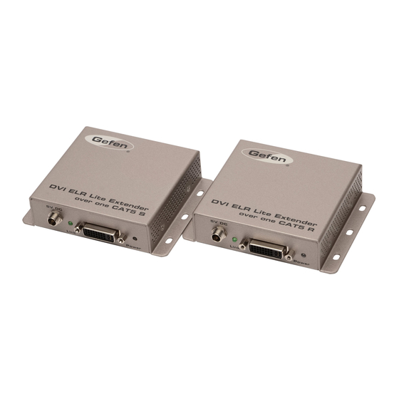
Introduction Sender Unit EXT-DVI-1CAT5-ELRS Gefen EXT-DVI-1CAT5-ELRS Gefen EXT-DVI-1CAT5-ELRS Gefen Link Link Link DVI ELR Extender DVI ELR Extender over one CAT5 S over one CAT5 S DVI ELR Extender over one CAT5 S 5V DC Link DVI In Power 5V DC... - Page 13 Introduction Name Description Link Connect a CAT-5 cable from this jack to the Link jack on the Receiver unit. 5V DC Connect the included 5V DC power supply to this power receptacle. Link (LED) This green LED indicates the current state of the product.
-
Page 14: Receiver Unit
Introduction Receiver Unit EXT-DVI-1CAT5-ELRR Gefen EXT-DVI-1CAT5-ELRR Gefen EXT-DVI-1CAT5-ELRR Gefen Link Link Link DVI ELR Extender DVI ELR Extender over one CAT5 R over one CAT5 R DVI ELR Extender over one CAT5 R 5V DC Link DVI Out Power 5V DC... - Page 15 Introduction Name Description Link Connect a CAT-5 cable from this jack to the Link jack on the Sender unit. 5V DC Connect the included 5V DC power supply to this power receptacle. Link (LED) This green LED indicates the current state of the product.
-
Page 16: Installation
Connect the included 5V DC locking power supplies to the Sender and Receiver unit. Do not overtighten the locking power connectors. Connect the AC power cord from the power supply to an available electrical outlet. Sample Wiring Diagram CAT5 CABLE DVI CABLE DVI Source Receiver Sender DVI Display EXT-DVI-1CAT5-ELR page | 6... -
Page 19: Basic Operation
DVI ELR Extender over one CAT5 Basic Operation LED Status ......................10 DIP Switch Configuration ..................11 Default Settings ................... 11 EDID Management ..................12 Hot-Plug Detect (HPD) ................12 Power Mode ....................13 Long-Reach Mode ..................13 page | 9... -
Page 20: Led Status
LED Status The Power and Link LED indicators on the Sender and Receiver unit provide basic information on the current status of the DVI ELR Extender over one CAT5. The information, in the table below, applies to both the Sender and Receiver unit. Status Description Power... -
Page 21: Dip Switch Configuration
DIP Switch Configuration EXT-DVI-1CAT5-ELRS Gefen There is a bank of four DIP switches on the bottom of the Sender and Receiver unit. Remove the piece of colored tape to reveal the DIP switch bank. These DIP switches Link provide control over EDID management, HPD pass-through, power modes, and range selection. -
Page 22: Edid Management
DIP Switch Configuration Each of the following sections describe the DIP switch settings that control each feature. DIP switches that are not related to a specific feature have been grayed-out. Note that DIP switch settings can be used independently or in conjunction with other features, as desired. EDID Management When switching between different EDID modes, the Sender unit must be power-cycled in order for the changes to take effect. -
Page 23: Power Mode
DIP Switch Configuration Power Mode Description Sender unit Receiver unit Power-Save (Green) mode. The Receiver unit is powered only when a video signal is present on the DVI (or HDMI) cable. Sleep Mode consumes less than 1 Watt of power. Normal mode. -
Page 25: Appendix
DVI ELR Extender over one CAT5 Appendix Specifications ...................... 16... -
Page 26: Specifications
Specifications Supported Formats Resolutions (max.) • 1920 x 1200 (WUXGA) • 1080p Full HD Connectors, Indicators, and Controls DVI In (Sender) • 1 x DVI-I, 29-pin, female (digital only) DVI Out (Receiver) • 1 x DVI-I, 29-pin, female (digital only) IP control (Sender / Receiver) •... - Page 28 *Preferred Stretch it. Switch it. Split it. Gefen’s got it. ® 20600 Nordhoff St., Chatsworth CA 91311 20600 Nordhoff St., Chatsworth CA 91311 1-800-545-6900 1-800-545-6900 818-772-9100 818-772-9100 fax: 818-772-9120 fax: 818-772-9120 www.gefen.com www.gefen.com support@gefen.com support@gefen.com...
Need help?
Do you have a question about the EXT-DVI-1CAT5-ELR and is the answer not in the manual?
Questions and answers