
Subscribe to Our Youtube Channel
Related Manuals for Master Image HORIZON3D


Summary of Contents for Master Image HORIZON3D
- Page 1 Installation & Operation Manual | HORIZON3D HORIZON3D Digital 3D Cinema System Installation & Operation Manual Revision No. 1.0.1...
- Page 2 Installation & Operation Manual | HORIZON3D Revision History Date Release Revision Author Remarks Status d1.0.0 September 2015 Initial Draft October 2015 d1.0.1 Draft Picture replacement November 2015 d1.0.2 Draft Drawing Replacement 1.0.0 December 2015 Release December 2015 1.0.1 Release Picture Replacement Copyright ©...
- Page 3 Installation & Operation Manual | HORIZON3D Locations MASTERIMAGE 3D, INC 15260 Ventura Blvd Suite 1220 Sherman Oaks CA 91403 TEL: (323) 606-7800 FAX: (323) 301-7985 MASTERIMAGE 3D ASIA, LLC. (Gasandong, BYC HIGHCITY Building A 22F), 131, Gasandigital1-ro, Geumcheon-gu, Seoul, 153-803, South Korea TEL.: +82-2-3438-1600...
-
Page 4: Table Of Contents
The New Horizon of Digital 3D Projection..............9 Installation and Configuration ................10 4.1. Unpacking the HORIZON3D ..................10 4.2. Confirm Package Contents of HORIZON3D ..............11 Detailed Component Overview ................12 5.1. Three-Way Beam Optical Head Assembly ..............12 Head Assembly – Component Identification ..............13 5.2. - Page 5 8.14. Factory Default via the Monitor Application ..............50 HORIZON3D Troubleshooting................51 9.1. Error Code Table ......................52 Appendix A – Firmware Upgrade for HORIZON3D ..........53 10.1. Prerequisites for Upgrading Firmware ................. 53 10.1.1. System Firmware Upgrade ................53 10.1.2. Web Server (MPFS) Upgrade ................53 10.1.3.
-
Page 6: Masterimage 3D, Inc
Installation & Operation Manual | HORIZON3D 11.1.2. Qube Server ...................... 69 11.1.3. GDC Server ....................... 72 Appendix C – Installation Record ................. 78 Appendix D – Dimensional Drawings ..............79 © MASTERIMAGE 3D, Inc. -
Page 7: Introduction
3D picture of any available liquid crystal 3D system. This user manual provides all the information required for simple installations and the operation of the HORIZON3D, with any DLP cinema projector and digital cinema server. 1.2. -
Page 8: Warnings And Cautions
Installation & Operation Manual | HORIZON3D 2. Warnings and Cautions 2.1. Installation Consideration When planning installation of the HORIZON3D, ensure that the auditorium throw ratio is greater than 1.1:1. 2.2. Heat Damage To avoid burning the polarizer film of the liquid crystal panel ensure a panel surface temperature of <80˚F is maintained. -
Page 9: System Overview
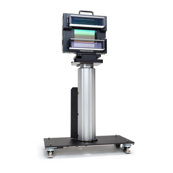
HORIZON3D provides an accurate synchronization function for both current format 72Hz, 24fps, triple flash and future HFR 3D formats. HORIZON3D is perfectly matched to the high quality polarized 3D eyewear produced by MASTERIMAGE 3D. HORIZON3D consists of the three-way beam optical head, lift column actuator and connection cables. -
Page 10: Installation And Configuration
4. Installation and Configuration 4.1. Unpacking the HORIZON3D Inspect the HORIZON3D packaging box for any external damage. Report any damage to shipper and to MasterImage 3D. Palletized Outer Carton contains Lifting Column, Optical Head Assembly and Accessories © MASTERIMAGE 3D, Inc. -
Page 11: Confirm Package Contents Of Horizon3D
Installation & Operation Manual | HORIZON3D 4.2. Confirm Package Contents of HORIZON3D Optical Three-Way Beam Head Assembly Lifting Column Unit Power Adaptor Sync Cable 3D Glasses Cleaning Cloths © MASTERIMAGE 3D, Inc. -
Page 12: Detailed Component Overview
Installation & Operation Manual | HORIZON3D 5. Detailed Component Overview 5.1. Three-Way Beam Optical Head Assembly © MASTERIMAGE 3D, Inc. -
Page 13: Head Assembly - Component Identification
Installation & Operation Manual | HORIZON3D Head Assembly – Component Identification 5.2. Front Panel A. Handle: Enables lifting or hand-carrying the Optical Head. B. Upper Half Image Outflow: Composed of the upper LCD and thick plate (Optional, To improve the alignment of the upper half image if required). - Page 14 K. Ethernet Port: Used for Automation, Alignment, Monitor Program & Firmware Upgrade of Control Panel. L. GPIO/TTL Port: Connected between HORIZON3D and DLP Projector for 3D SYNC Input and automation function. M. Actuator Port: Connected between Control Panel and lift-column actuator to move the Optical Head between 3D position or 2D position.
-
Page 15: Lift Column Actuator
B. Lift Column Actuator: Used to move the Optical head between 3D position or 2D position. C. Lift Colum Actuator Control Box D. Rolling wheels: Used to move the HORIZON3D; wheels are then locked to secure the unit in place. E. DC Power Port: DC +24V/5A adaptor. -
Page 16: System Setup
Installation & Operation Manual | HORIZON3D 6. System Setup 6.1. Initial System Assembly 6.1.1. Attach Optical Head to Tilt Angle Stage Before attaching the Optical Head Assembly, observe the two guide pins of Tilt Angle Stage on Lift Column Actuator. -
Page 17: Cable Connections
Installation & Operation Manual | HORIZON3D 6.1.2. Cable Connections A. Connecting the GPIO SYNC cable 1. Connect the SYNC cable to the Optical Head Assembly GPIO/TTL port. 2. Tighten both screws securely. 3. Connect the other end to the DLP Projectors GPIO Port. -
Page 18: Initial Installation Consideration
At this time, press the 3D or 2D button and the Lift Actuator Column will lower to the Zero Position automatically. The Lift Actuator Column must be lowered to the Zero Position before moving the HORIZON3D. © MASTERIMAGE 3D, Inc. -
Page 19: Setting 3D Position
Installation & Operation Manual | HORIZON3D 6.1.4. Setting 3D Position 1. With the System Power ‘On’ the 7-segment display will show 3D Position “00” on the Control Panel. If the GPIO SYNC cable is connected with the DLP projector, then the display will show the sync frequency being output. -
Page 20: Setting 2D Position
Installation & Operation Manual | HORIZON3D 6.1.5. Setting 2D Position DOWN 8. Press the 2D button to activate the Lift Column Actuator and move the position downwards. The 2D button’s LED will blink. 2D Position 9. When the Optical Head has cleared the zoom lens and is at the position you want it to be, release the 2D button. -
Page 21: Verifying 3D & 2D Position And Locking Feet
Installation & Operation Manual | HORIZON3D 6.1.6. Verifying 3D & 2D Position and Locking Feet 3D Position 13. Press 3D button. While the Lift Actuator Column is moving to the 3D position, the 3D button LED blinks on and off. -
Page 22: System Alignment
Installation & Operation Manual | HORIZON3D 6.2. System Alignment 6.2.1. Adjusting Optical Head Assembly Position Turing the Tilt Knob clockwise Adjusting the 3D position slightly To achieve the best 3D display, the Optical Head must be installed properly and aligned optimally. -
Page 23: Image Alignment - Manual
Installation & Operation Manual | HORIZON3D 6.2.2. Image Alignment – Manual Alignment Covers Lock Screw Mirror Lock Screws Before carrying out Image Alignment the Mirror Locking Screws must be removed. - Tool Required: 2mm or 5/64” hex key wrench (Type: Small Right... - Page 24 Installation & Operation Manual | HORIZON3D Upper Vertical Alignment screw Upper Horizontal Alignment screw Upper Half Image Alignment To achieve the best 3D display, the Optical Head must be installed properly and aligned optimally. Tools Required: 2mm or 5/64” hex key wrench (Type: Small Right Angle) 3.
- Page 25 Installation & Operation Manual | HORIZON3D Lower Horizontal Alignment screw Lower Vertical Alignment screw Lower Half Image Alignment To achieve the best 3D display, the Optical Head must be installed properly and aligned optimally. Tools Required: 2mm or 5/64” hex key wrench (Type: Small Right Angle) 7.
- Page 26 Installation & Operation Manual | HORIZON3D Alignment Covers Alignment Covers After Image Alignment the Alignment Covers must be closed 10. To protect the dust or foreign substances, the four alignment covers must be closed by tightening the thumb screws by hand.
-
Page 27: Image Alignment - Wireless
Installation & Operation Manual | HORIZON3D 6.2.3. Image Alignment – Wireless Alignment Covers Lock Screw Mirror Lock Screws Before carrying out Image Alignment the Mirror Locking Screws must be removed. - Tool Required: 2mm or 5/64” hex key wrench (Type: Small Right... - Page 28 Initially connect your mobile device to the wireless network and open your web browser, e.g. Safari. Enter the IP address of the HORIZON3D and you will be taken to the wireless Alignment Controller home page as below: Initially the button displaying the...
- Page 29 Installation & Operation Manual | HORIZON3D Pressing the x1 button so it displays green indicates that the wireless Alignment Controller feature is active in ‘low-speed’ mode. Use this mode for slower, more accurate alignment if the image once the correct position has nearly been reached.
- Page 30 Installation & Operation Manual | HORIZON3D Alignment Covers Alignment Covers After Image Alignment the Alignment Covers must be closed 3. To protect the dust or foreign substances, the four alignment covers must be closed by tightening the thumb screws by hand.
-
Page 31: Phase Sync Polarity
Installation & Operation Manual | HORIZON3D 6.3. 3D Phase Sync Polarity If necessary it is possible to change the sync polarity of the 3D phase by changing the position of DIP switch 2 on the Optical Head Assembly next to the Ethernet RJ-45 Connector. -
Page 32: Projector Configuration
7.1. Projector 3D File Configuration The projector’s 3D control file must be configured to work with the HORIZON3D. These procedures describe configuring the control files for Series II projectors. The Dark Time should be set to 350µS with the Delay being set to -100µS. These figures are applicable to all frame rates and projector flash configurations. -
Page 33: Christie Series Ii File Settings For External Server Playback
Installation & Operation Manual | HORIZON3D 7.2.2. Christie Series II File Settings for External Server Playback Christie 7.2.3. Barco Series II File Settings for External Server Playback Barco © MASTERIMAGE 3D, Inc. -
Page 34: Imb Configuration Settings
Installation & Operation Manual | HORIZON3D Barco Series II projectors have a pre-installed 3D configuration file for the settings required by the CLARITY3D system. It is possible to select this file rather than making fully manual entries, but editing of Dark Time and Output Reference Delay would be required. -
Page 35: System Setup Using The Monitor Application
8. System Setup Using the Monitor Application 8.1. Initial Configuration Connect your PC to the HORIZON3D with an Ethernet cable and configure your network settings with Control Panel of Microsoft Windows. You can use a different IP address that is suitable to your network 8.2. -
Page 36: Changing The User Password
To prevent access to the HORIZON3D from unauthorized persons it is possible to change the system password. Click the [New Password] link in the upper right corner of the HORIZON3D Web Server shown above and the ‘Change Password’ dialog box will be displayed. -
Page 37: System Operation Via The Monitor Application
Installation & Operation Manual | HORIZON3D Input the current password. (mi) • Input a new password. • Input the new password for confirmation and click the [Save password] • button. 8.3. System Operation via the Monitor Application Click the [RUN] button to start the Liquid Crystal Panel operation. -
Page 38: Position Movement Via The Monitor Application
Installation & Operation Manual | HORIZON3D The color of the [RUN] button will change from black to green. The indication under Status will change from ‘Ready’ to ‘Running’. Once synchronized the Liquid Crystal Panel operating frequency will be displayed. 8.4. -
Page 39: Position
Installation & Operation Manual | HORIZON3D 8.4.2. 2D Position Click the [2D] button to move the actuator to the 2D position. The color of the [3D] button will change from green to black. The color of the [2D] button will change from black to green. -
Page 40: Sync Polarity Via The Monitor Application
Installation & Operation Manual | HORIZON3D 8.5. Sync Polarity via the Monitor Application Check the current value of the Sync Polarity. Depending on the condition of 3D material on screen change the Sync Polarity as required from ‘True’ to ‘Invert’. -
Page 41: Setting 3D Position Via The Monitor Application
Installation & Operation Manual | HORIZON3D 8.6. Setting 3D Position via the Monitor Application Check the current setting for the 3D position of the Actuator. If required by the installation requirements for the system the 3D Position can be changed from ‘Left’... -
Page 42: Automation Source Via The Monitor Application
Installation & Operation Manual | HORIZON3D 8.7. Automation Source via the Monitor Application Check the current setting for the Automation Source of the system, by default this is set to ‘Manual’. The options available for selection are: Manual – Control via front panel button ... -
Page 43: Sync Pulse Automation Reference Frequency Via The Monitor Application
Installation & Operation Manual | HORIZON3D 8.8. Sync Pulse Automation Reference Frequency via the Monitor Application Set the reference frequencies when the automation source is set to Sync Pulse. Once the Automation Source has been set to Sync Pulse click [Reference Sync] in the bottom left of the application. -
Page 44: Delay Time Via The Monitor Application
Installation & Operation Manual | HORIZON3D 8.9. 2D Delay Time via the Monitor Application When using the Sync Pulse Automation option with material of varying frequency or frame rate it may be necessary to apply 2D Delay Time to the system to prevent unwanted 2D transition. -
Page 45: Ethernet Automation Port Number Allocation
Installation & Operation Manual | HORIZON3D 8.10. Ethernet Automation Port Number Allocation When using the Ethernet Automation feature configure the port number being used. The default setting is 5000. Once the Automation Source has been set to the Ethernet option the Port Number can be configured accordingly. -
Page 46: Network Configuration Via The Monitor Application
Installation & Operation Manual | HORIZON3D 8.11. Network Configuration via the Monitor Application Configure the network settings of the HORIZON3D to operate on your network via ethernet communication. Click [Network Configuration] to access the settings window. Enter the IP Address, Gateway, Subnet Mask, Primary DNS and Secondary DNS of your network accordingly. -
Page 47: Sync Source Via The Monitor Application
Installation & Operation Manual | HORIZON3D 8.12. Sync Source via the Monitor Application Check the current setting for the Sync Source. The default is [GPIO]. Choose the option for [TTL] if the system is being used in a non-cinema application. -
Page 48: Log File Via The Monitor Application
Installation & Operation Manual | HORIZON3D 8.13. Log File via the Monitor Application The system contains a log function that stores the last 200 records of activity including any errors that occurred. In order to access the log file click [Log] at the top of the Monitor Application. - Page 49 Installation & Operation Manual | HORIZON3D Description # POWER ON : v1.0.0 Power On : Firmware Version Number RUNNING RUNNING STOP STOP Current Position : 2D 2D MOVING Actuator Moving to 2D Position Current Position : 3D Status 3D MOVING...
-
Page 50: Factory Default Via The Monitor Application
Installation & Operation Manual | HORIZON3D 8.14. Factory Default via the Monitor Application Should it be necessary for any reason to reset the system to Factory Default this can be achieved by clicking the [Default] button. This can be completed for operational settings or network configuration. -
Page 51: Horizon3D Troubleshooting
Before contacting the nearest reseller/dealer or support@masterimage3d.com, check the below items. 1. Make sure that you have properly connected the HORIZON3D to peripheral equipment. 2. Check all cable connections. Make sure that all computer, projector, and power cords are properly connected. -
Page 52: Error Code Table
Installation & Operation Manual | HORIZON3D 9.1. Error Code Table Potential error codes displayed on the 7-segment display along with their meanings are shown in the table below: ERROR CODE LOG TEXT MEANING ERR : ACT NOT DETECT Actuator/Lift stand is not connected... -
Page 53: Appendix A - Firmware Upgrade For Horizon3D
10.1.3. Lifting Column Firmware Upgrade 1. From the ftp site download and install the USB_Downloader driver package. 2. Download and save the latest indicated lifting column update file for the HORIZON3D. Example: 20150806_horizon_lift_app_ver1.9.hex 3. Prepare a micro-USB cable for connection to the lifting column. -
Page 54: Web Server (Mpfs) Upgrade Procedure
1. If an MPFS Upgrade is indicated as being required this must be completed before the System Firmware is upgraded. 2. Connect to the HORIZON3D system via Ethernet cable and launch the Monitor Application as described in section 8 of this manual. -
Page 55: System Firmware Upgrade Procedure
Installation & Operation Manual | HORIZON3D 10.3. System Firmware Upgrade Procedure 1. Connect the HORIZON3D control box to your PC with the Ethernet cable. 2. Execute “MITftp” utility by double-clicking the utility’s icon on your PC. Device’s IP Address TFTP Port number 192.168.10.95) - Page 56 Installation & Operation Manual | HORIZON3D 4. Click the [Open] button to select the firmware (.hex) file saved to your PC. 5. Select the file to be used and click [Open]. 6. Click the [Upgrade] button to start the upgrade of the selected file to the system.
- Page 57 Installation & Operation Manual | HORIZON3D 7. You will see the “Start Firmware Upgrade” message in the utility after pressing the [Upgrade] button. 8. You will see the “Success Firmware Upgrade” message in the utility after the progress bar reaches the end.
-
Page 58: Lifting Column Firmware Upgrade Procedure
10.4. Lifting Column Firmware Upgrade Procedure 1. Make sure the HORIZON3D system is disconnected from the power supply and connect the micro-USB cable as indicated in the image below. 2. Having installed the USB_Downloader driver file on your computer, run the ‘MasterImage 3D Bootloader’... - Page 59 Installation & Operation Manual | HORIZON3D 3. Connect the power to the HORIZON3D system and the PICDEM FS USB0 (Boot) will be automatically selected by the software. 4. Click the ‘Load HEX File’ button and locate the previously saved upgrade file on your computer e.g.
- Page 60 Installation & Operation Manual | HORIZON3D 5. Click the ‘Program Device’ button and the upgrade will commence, once complete a success message will be displayed. 6. Disconnect the micro-USB cable and power cable; the next time the system is powered on the update will be applied.
-
Page 61: Appendix B - Horizon3D Automation
Installation & Operation Manual | HORIZON3D 11. Appendix B – HORIZON3D Automation Table B-1. GPIO/TTL Automation DSUB(GPIO/TTL) DSUB37 Comm. Description Comments Direction Pin Name Pin Number Pin Number No Connection ← Liquid Crystal Panel Module PRJ_COM_nRUN RUN command Compartor 24V max, ←... - Page 62 Installation & Operation Manual | HORIZON3D Table B-2. GPIO/TTL Automation DSUB(GPIO/TTL) DSUB37 Comm. Description Comments Direction Pin Name Pin Number Pin Number Compartor ← 24V max, PRJ_SYNC SYNC pulse 12V threshold (LM2901H) 13,14 Ground CHASSIS_GND Frame Frame Chassis Ground © MASTERIMAGE 3D, Inc.
-
Page 63: Ethernet Automation
3. Select the Raw option to create MasterImage as a known device in the server’s listing. 4. Complete the fields as shown below. Ensure the settings entered match those of the HORIZON3D for IP Address and Port Number. Check the Enabled box and save the entry. - Page 64 Installation & Operation Manual | HORIZON3D The HORIZON3D has now been successfully added into the server configuration. It is now possible to create the macro files to enable the server to control the HORIZON3D. The files required are: MasterImage Start, MasterImage Stop, MasterImage 2D, MasterImage 3D and MasterImage Up/Down Stop.
- Page 65 Installation & Operation Manual | HORIZON3D 2. After the item has been created click OK return to the main Macro Editor screen. Repeat this process for the other four required macros, MasterImage Stop, MasterImage 2D, MasterImage 3D and MasterImage Up/Down Stop.
- Page 66 Installation & Operation Manual | HORIZON3D 4. Highlight the Input/Output option and Send Message, and then click the Add button. The following configuration window will appear: 5. In this window, choose the device MasterImage from the Device name dropdown list and type in the Message label of MasterImage Start.
- Page 67 Installation & Operation Manual | HORIZON3D In future versions of Doremi software updates, the MasterImage macros will be included in a file named MasterImage_cueslib. This will remove the requirement for the information to be entered manually as described in the above steps.
- Page 68 Installation & Operation Manual | HORIZON3D © MASTERIMAGE 3D, Inc.
-
Page 69: Qube Server
11.1.2. Qube Server To create automation macros for the HORIZON3D in the Qube server it is necessary to edit two XML files within the server’s configuration. The files in question are located in the path C:/Program Files/Qube Cinema/XP and are named automationdevices.xml and automationcues.xml... - Page 70 Finally the automationcues.xml file can be edited so that the HORIZON3D device is associated with the command names that have been created. This allows the cues to be seen in the Qube graphical interface.
- Page 71 Installation & Operation Manual | HORIZON3D <Cue name="Start 3D"> <Actions> <InvokeMethod name="Start" device="MasterImage"/> </Actions> </Cue> <Cue name="Stop 3D"> <Actions> <InvokeMethod name="Stop" device="MasterImage"/> </Actions> </Cue> <Cue name="3D Position"> <Actions> <InvokeMethod name="3Dposition" device="MasterImage"/> </Actions> </Cue> <Cue name="2D Position"> <Actions> <InvokeMethod name="2Dposition" device="MasterImage"/>...
-
Page 72: Gdc Server
Installation & Operation Manual | HORIZON3D 11.1.3. GDC Server The steps described below are specific to the GDC SX-2001 server. If information is required for different models, please contact GDC directly. 1. In the SMS Main Menu click the Control Panel button and log on as Maintenance Access. - Page 73 Installation & Operation Manual | HORIZON3D The HORIZON3D must be added as a device within the GDC server configuration. 3. Select the Devices tab and click the Add button. The following screen will display: © MASTERIMAGE 3D, Inc.
- Page 74 4. Name the new device MasterImage, and ensure the Type selection is set to NETWORKSOCKET, then click OK. 5. In the next screen, enter the configuration settings for the HORIZON3D IP Address and Port Number. 6. In the Transport option select TCP and in the Linefeed Type select CR and ensure the Status is set to Enabled.
- Page 75 Installation & Operation Manual | HORIZON3D 9. Click the Add button to create a new event. In this case, name the event START. 10. Click the Enter button and enter the command value for the event. Again in this case, START.
- Page 76 Installation & Operation Manual | HORIZON3D 11. Click the Enter button to save this change, then go back and make entries for the remaining four macros that are required. Event Name STOP Enter Value STOP Event Name 2D POSITION Enter Value PFD DOWN...
- Page 77 Installation & Operation Manual | HORIZON3D 15. Once all event actions have been created click the Save button followed by Yes. © MASTERIMAGE 3D, Inc.
-
Page 78: Appendix C - Installation Record
Installation & Operation Manual | HORIZON3D 12. Appendix C – Installation Record The form below is an example of the installation record form to be filled out once the HORIZON3D has been set up and configured. For a copy of the form to be filled out, ‘contact your equipment provider or email a request to support@masterimage3d.com. -
Page 79: Appendix D - Dimensional Drawings
Installation & Operation Manual | HORIZON3D 13. Appendix D – Dimensional Drawings © MASTERIMAGE 3D, Inc. - Page 80 Installation & Operation Manual | HORIZON3D Optical Head Assembly © MASTERIMAGE 3D, Inc.
- Page 81 Installation & Operation Manual | HORIZON3D End of Manual For additional information, go to www.support.masterimage3d.com. © MASTERIMAGE 3D, Inc.
Need help?
Do you have a question about the HORIZON3D and is the answer not in the manual?
Questions and answers