Table of Contents
Advertisement
Quick Links
Advertisement
Table of Contents

Related Manuals for Advantech PPC-V106


Summary of Contents for Advantech PPC-V106
- Page 1 PPC-V106 Fanless Vehicle Mounted Terminal with 10.4" TFT LCD User’s Manual...
- Page 2 SMI is a trademark of Silicon Motion, Inc. Creative is a trademark of Creative Technology LTD. All other product names or trademarks are properties of their respective owners. For more information on this and other Advantech products, please visit our websites at: http://www.advantech.com http://www.advantech.com.tw For technical support and service, please visit our support website at: http://service.advantech.com.tw/eservice...
- Page 3 FCC Class B This equipment has been tested and found to comply with the limits for a Class B digital device, pursuant to Part 15 of the FCC Rules. These limits are designed to provide reasonable protection against harmful interfer- ence when the equipment is operated in a residential environment.
-
Page 4: Packing List
Packing List Before you begin installing your card, please make sure that the following materials have been shipped: • PPC-V106 series panel PC • Accessories for PPC-V106 - Warranty card - Power cord: For AC Model: US type AC power cord. - Page 5 Additional Information and Assistance Step 1. Visit the Advantech web site at www.advantech.com or www.advantech.com.tw where you can find the latest informa- tion about the product. Step 2. Contact your distributor, sales representative, or Advantech's cus- tomer service center for technical support if you need additional assistance.
-
Page 6: Safety Instructions
The sound pressure level at the operator's position according to IEC 704-1:1982 is no more than 70 dB (A). DISCLAIMER: This set of instructions is given according to IEC 704-1. Advan- tech disclaims all responsibility for the accuracy of any statements contained herein. PPC-V106 User Manual... - Page 7 Wichtige Sicherheishinweise 1. Bitte lesen sie Sich diese Hinweise sorgfältig durch. 2. Heben Sie diese Anleitung für den späteren Gebrauch auf. 3. Vor jedem Reinigen ist das Gerät vom Stromnetz zu trennen. Verwenden Sie Keine Flüssig-oder Aerosolreiniger. Am besten dient ein angefeuchtetes Tuch zur Reinigung.
- Page 8 DISCLAIMER: This set of instructions is given according to IEC704-1. Advantech disclaims all responsibility for the accuracy of any statements contained herein. PPC-V106 User Manual viii...
-
Page 9: Table Of Contents
Setting Jumpers ............... 22 4.1.1 Jumpers and Switches........... 23 Table 4.1:Jumpers and their functions......23 4.1.2 Locating Jumpers and Switches........23 Figure 4.1:Locating Jumpers on the PPC-V106 Mother- board ..............23 4.1.3 Connectors ..............24 Table 4.2:Panel PC connectors ........24 4.1.4 Locating Connectors ............. - Page 10 Driver Installation for Windows 2000 ......45 Driver Installation for Windows ME / 98 / 98SE.... 46 Further Information ............46 Chapter 10 Touchscreen ............48 10.1 Introduction ..............48 10.1.1 General information............48 10.1.2 General specifications........... 48 PPC-V106 User Manual...
- Page 11 10.1.3 Environmental specifications........49 10.2 Installation of Touchscreen Drivers ........ 49 10.2.1 Installation for Windows 98/ME ........50 10.2.2 Installation for Windows 2000/XP ....... 51 10.3 Further Information ............51 Appendix A Programming the Watchdog Timer .....54 Programming the Watchdog Timer......... 54 Appendix B Pin Assignments ..........58 Inverter Power Connector (CN10) ........
- Page 12 PPC-V106 User Manual...
- Page 13 General Information This chapter gives background information on the PPC-V106 panel Sections include: • Introduction • General Specifications • LCD Specifications • Dimensions...
-
Page 14: Chapter 1 General Information
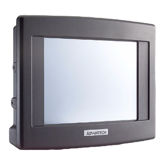
Chapter 1 General Information 1.1 Introduction PPC-V106 is fanless and comes with a VIA Eden low-power CPU for higher reliability and performance. The ruggedized aluminum enclosure without ventilation holes makes PPC-V106 waterproof and dust proof. A variable power source suits vehicles such as forklifts and trucks, which typically operate anywhere from 12 to 48 VDC. - Page 15 • Front panel: IP65/NEMA4 compliant • Enclosure: Ruggedized aluminum without ventilation holes Standard PC functions • CPU: Embedded VIA Eden 800 MHz CPU • BIOS: Award 256 KB Flash BIOS, supports Plug & Play, APM • System Chipset: VIA CLE266 and VT8235 CD •...
- Page 16 32-bit Cardbus (Card-32) and the 16-bit PC card (Card-16) without external buffers • Hot insertion and removal Touchscreen (Optional) Type Analog Resistive Resolution Continuous Light Transmission Controller RS232 interface (uses COM4) Power Consumption <5 V@ 100 mA Software Driver Supports Windows 98/2000/ME/XP PPC-V106 User Manual...
-
Page 17: Lcd Specifications
The color LCD display installed in the panel PC is high-quality and reliable. However, it may contain a few defective pixels which do not always illuminate. With current technology, it is impossible to completely eliminate defective pixels. Advantech is actively working to improve this technology. Chapter 1... -
Page 18: Dimensions
1.4 Dimensions PPC-V106 User Manual... - Page 19 System Setup This chapter details system setup on the PPC-V106 Panel PC. Sections include: • A Quick Tour of the Panel PC • Installation procedures • Running the BIOS Setup Program...
-
Page 20: Chapter 2 System Setup
Figure 2.1: Front View of the Panel PC When you look at the right side of the panel PC, you will see the holes for mounting as shown in Fig. 2-2. Figure 2.2: Right Side of Panel PC PPC-V106 User Manual... - Page 21 When you turn the Panel PC around and look at its rear cover, you will find VESA standard holes and others for mounting. There are no ventila- tion holes, as shown in Figure 2-3. Figure 2.3: Rear Side View of the Panel PC The I/O section is at the bottom of the panel PC, as shown in Fig.
-
Page 22: Installation Procedures
2.2 Installation Procedures 2.2.1 Connecting the Power Cord There are two kinds of power supplies for the PPC-V106 series, AC and For AC model : The Panel PC can only be powered by an AC electrical outlet (100 ~ 250 volts, 50 ~ 60 Hz). -
Page 23: Running The Bios Setup Program
2.3 Running the BIOS Setup Program Your panel PC is likely to have been properly set up and configured by your dealer prior to delivery. You may still find it necessary to use the panel PC's BIOS (Basic Input-Output System) setup program to change system configuration information, such as the current date and time or your type of hard drive. -
Page 24: Installing System Software
If you are presented with an operating system command prompt, such as A:\>, then you must partition and format your hard drive, and manually copy the operating system files to it. Refer to your operating system user's manual for instructions on partitioning and formatting a hard drive. PPC-V106 User Manual... -
Page 25: Installing The Drivers
These files are a very useful supplement to the information in this man- ual. Note: The drivers and utilities used for the PPC-V106 panel PCs are subject to change without notice. If in doubt, check Advantech's website or contact our application engineers for the latest informa- tion regarding drivers and utlities. - Page 26 PPC-V106 User Manual...
-
Page 27: Peripheral Installation
Hardware and Peripheral Installation This chapter details the installation of the PPC-V106 panel PC hardware. Sections include: • Overview of Hardware Installation and Upgrading • Installing the 2.5" Hard Disk Drive (HDD) • Installing the Universal Arm • Placing the Rubber Seal... -
Page 28: Chapter 3 Hardware And Peripheral Installation
IDE hard drive to exceed 528 MB. The following are instruc- tions for installation: Detach the HDD bracket by unscrewing the four screws (#2) on the top of the HDD bracket. Screws 1930030400-M3x4L 1933030500-M3x5L 1930000112-M3x8L (Fixed, don't unscrew) PPC-V106 User Manual... - Page 29 Place the HDD inside the HDD bracket and tighten four screws (#1) from both sides of the HDD bracket. HDD (Bottom up) Pin 1 The HDD cable (1 x 44-pin to 1 x 44-pin) is next to the HDD bracket. Connect the HDD cable to the HDD. Make sure that the red wire corresponds to Pin 1 on the connector, which is labelled on the board.
- Page 30 Note 3 HDD installation procedures for the PPC-V106 is subject to change without notice. If in doubt, check Advantech's website. (www.advantech.com) or contact our application engineers for the latest information. PPC-V106 User Manual...
-
Page 31: Installing The Universal Arm
Rotate support-2 until the angle is the same as support-1. Use four M4x8L screws and attach the U-Arm with the PPC-V106. Use latches adjust the angle of PPC-V106 (every 14.4° on 360°). Note: Support-1 can be on the right or left. -
Page 32: Placing The Rubber Seal
3.4 Placing the Rubber Seal To ensure that your PPC-V106, the supplied rubber seal must be placed correctly between the front bezel and back cover. Please note the direc- tion of the seal. The mark should be up. Marked Flat (UP) Figure 3.2: Placing the Rubber Seal... - Page 33 Jumper Settings and Connectors This chapter tells how to set up the panel PC hardware, including instruc- tions on setting jumpers and connecting peripherals, switches and indicators. Be sure to read all the safety precautions before you begin the installation proce- dures.
-
Page 34: Chapter 4 Jumper Settings And Connectors
If you have any doubts about the best hardware configuration for your application, contact your local distributor or sales representative before you make any changes. An arrow is used on the motherboard to indicate the first pin of jumpers. PPC-V106 User Manual... -
Page 35: Jumpers And Switches
COM1 / COM2/ COM3 pin 9 output type setting COM1 / COM2/ COM3 pin 9 output type setting COM2 RS232/422/485 setting Panel type setting (Reserved) 4.1.2 Locating Jumpers and Switches Figure 4.1: Locating Jumpers on the PPC-V106 Motherboard Chapter 4... -
Page 36: Connectors
2.5 " IDE connector CN16 Floppy drive connector (Reserved) CN17 CFC connector CN18 Slim type CD-ROM/IDE connector CN20 USB 3 CN21 USB 4 CN23 COM4 connector CN24 Mini PCI socket CN26 COM 3 connector CN27 Front panel connector PPC-V106 User Manual... -
Page 37: Locating Connectors
4.1.4 Locating Connectors Figure 4.2: Locating Connectors on the PPC-V106 Motherboard 4.2 CPU Installation The CPU is embedded on the motherboard, so there are no settings for frequency ratio or voltage. Chapter 4... -
Page 38: Cmos Clear For External Rtc (Jp1)
COM2: RS-232/422/485 (in one COM port connector). 4.4.1 COM2 RS-232/422/485 Setting (JP5) COM2 can be configured to operate in RS-232, RS-422, or RS-485 mode. This is done via JP5 settings. Table 4.4: COM2 RS-232/422/485 setting (JP5) *RS-232 RS-422 RS-485 PPC-V106 User Manual... - Page 39 The IRQ and the address ranges for COM1, COM2, COM3 and COM4 are fixed. However, if you wish to disable the port or change these parameters later you can do this in the system BIOS setup. The table overleaf shows the default settings for the panel PC’s serial ports.
-
Page 40: Com1/Com2/Com3/ Pin 9 Output Setting (Jp4)
Pins 1, 3 and 5 are for COM1 Pins 2, 4 and 6 are for COM2 Pins 7, 9 and 11 are for COM3 When enabling this function, you should remove a jumper from JP3 as shown in table 4.7. PPC-V106 User Manual... - Page 41 Table 4.7: JP3 Setting Normal (default) Remove jumper from pin 1 and 2 to make pin 9 on COM1 a power output. Remove jumper from pin 3 and 4 to make pin 9 on COM2 a power output. Remove jumper from pin 5 and 6 to make pin 9 on COM3 a power output.
-
Page 42: Vga Interface
The panel PC's AGP SVGA interface supports 5 V and 3.3 V LCD dis- plays. The default setting is 3.3 V (connecting pin 2 and 3), but you can use JP2 to change this to 5 V. (connecting pin 1 and 2). PPC-V106 User Manual... - Page 43 VIA Chipset This chapter provides information on Intel chipset configuration • Introduction • Further information...
-
Page 44: Chapter 5 Via Chipset
Chapter 5 VIA Chipset 5.1 Introduction The PPC-V106 uses the combination of VIA CLE266 north bridge and VT8235 CD south bridge. The VIA CLE266 chipset is an innovative integrated graphics chipset developed with DDR266 memory and optimized to support the VIA C3 and VIA Eden Series processors, adding intelligence to help manage and prioritize multiple threads received from the microprocessor. - Page 45 AGP SVGA Setup • Introduction • Installation of SVGA Driver for Windows 98/ME for Windows 2000/XP • Further Information...
-
Page 46: Chapter 6 Agp Svga Setup
Chapter 6 AGP SVGA Setup 6.1 Introduction The PPC-V106 has an onboard integrated VGA chipset The specifica- tions and features are described as follows: 6.1.1 Chipset The VIA CLE266 boasts a complete integrated VIA 128-bit 2D/3D graphics engine with a high quality video processing unit including MPEG-2 decoding, video scaling and Alpha Blending. -
Page 47: Installation For Windows 98/Me
"browse" 6.2.2 Installation for Windows 2000/XP Click the 'Start' button in the task bar, click 'Run' and then select 'Setup.exe' from D:\PPC-V106\VGA\2k_xp\Setup.exe. The Install dialog will appear. click 'Next' to continue. Read License Agreement and click "Yes" to proceed. - Page 48 PPC-V106 User Manual...
- Page 49 PCI Bus Ethernet Interface This chapter provides information on Ethernet configuration. • Introduction • Installation of Ethernet Driver - for Windows 98/ME - for Windows 2000/XP • Further Information...
-
Page 50: Chapter 7 Pci Bus Ethernet Interface
7.2 Installation of Ethernet Driver Before installing the Ethernet driver, note the procedures below. You must know which operating system you are using in your PPC-V106, and then refer to the corresponding installation flow chart. Then just follow the steps described in the flow chart. You will quickly and successfully complete the installation, even if you are not familiar with instructions for Windows. -
Page 51: Installation For Windows 98/Me
Ethernet hardware and install the Ethernet driver from the drivers database from Windows 2000, Windows XP when the system reboots. It is recommended that you upgrade to the Intel driver provided with the CD. To upgrade to this driver, use this path : D:\PPC-V106\Lan\setup.exe Chapter 7... -
Page 52: Further Information
7.3 Further Information Realtek website: www.realtek.com.tw Advantech website: www.advantech.com PPC-V106 User Manual... - Page 53 Audio • Introduction • Installation of Audio Driver...
-
Page 54: Chapter 8 Audio
8.2 Installation of Audio Driver Before installing the audio driver, please take note of the procedures detailed below. You must know which operating system you are using in your PPC-V106, and then refer to the corresponding installation proce- dure. Important: The following are examples only. - Page 55 USB 2.0 This chapter describes how to install the USB 2.0 driver...
-
Page 56: Chapter 9 Usb 2.0
9.1 Installation of USB 2.0 Driver Before installing the audio driver, please take note of the procedures detailed below. You must know which operating system you are using in your PPC-V106, and then refer to the corresponding installation proce- dure Important : The following Windows illustrations are exam- ples only. -
Page 57: Driver Installation For Windows 2000
Bus (USB) Controller” under “Other devices”. Execute the setup program by double click on the “SETUP.exe” file in \PPC-V106\USB2.0 The screen shows the VIA Software License Agreement. Please read it FIRST and press “Yes” if wish to further proceed with the driver installation. -
Page 58: Driver Installation For Windows Me / 98 / 98Se
Note: For Driver Uninstallation, the user can remove the “Microsoft USB 2.0 Host Controller Driver” by selecting the “Uninstall” button. This will completely remove the driver from the system. 9.5 Further Information VIA web site : http://www.via.com.tw Advantech website: www.advantech.com PPC-V106 User Manual... - Page 59 Touchscreen • Introduction • Installation of Touchscreen Drivers for Windows 98/ME for Windows 2000/XP...
-
Page 60: Chapter 10 Touchscreen
For more detailed information, please visit the following websites: www.dynapro.com www.3m.com/us/electronics_mfg/touch_systems www.elotouch.com Advantech Co.,Ltd. reserves the right to alter the touchscreen at any time without notice. 10.1.2 General specifications Please refer to Chapter 1, Section 1.2 of this manual. PPC-V106 User Manual... -
Page 61: Environmental Specifications
10.2 Installation of Touchscreen Drivers The touchscreen driver for Windows contains a native, 32-bit driver and a 32-bit control panel program for the PPC-V106 system. To facilitate installation of the touchscreen driver, you should read the instructions in this section carefully before you attempt installation. -
Page 62: Installation For Windows 98/Me
10.2.1 Installation for Windows 98/ME To install the software to PPC-V106, your PPC-V106 must have Win- dows 98/Me system running and installed PenMount Series Interface control board already. If you have an older version of PenMount Win- dows 98/Me driver installed in your PPC-V106, please remove it first. -
Page 63: Installation For Windows 2000/Xp
10.2.2 Installation for Windows 2000/XP To install the software to PPC-V106, your PPC-V106 must have Win- dows 2000/XP system running and installed PenMount Series Interface control board already. If you have an older version of PenMount Win- dows 2000/XP driver installed in your PPC-V106, please remove it first. - Page 64 PPC-V106 User Manual...
-
Page 65: Watchdog Timer
Programming the Watchdog Timer The PPC-V106 is equipped with a watchdog timer that resets the CPU or generates an interrupt if processing comes to a standstill for any reason. This feature ensures system reliability in industrial standalone or unmanned environments. -
Page 66: Appendix A Programming The Watchdog Timer
I/O port 440 (hex). The following example shows how you might program the watchdog timer : ;----------------------------------------------------------------------------------- ; Enter the extended function mode , interruptible double-write | ;----------------------------------------------------------------------------------- MOV DX,2EH MOV AL,87H OUT DX,AL OUT DX,AL PPC-V106 User Manual... - Page 67 ;----------------------------------------------------------------------------- ; Configurate logical device 8, configuration register CRF6 | ;----------------------------------------------------------------------------- MOV DX,2EH MOV AL,07H ; point to Logical Device Number Reg. OUT DX,AL MOV DX,2FH MOV AL,08H ; select logical device 8 OUT DX,AL MOV DX,2EH MOV AL,30H ;Set watch dog activate or inactivate OUT DX,AL MOV DX,2FH MOV AL,01H ;...
- Page 68 ;------------------------------------------ ; Exit extended function mode | ;------------------------------------------ MOV DX,2EH MOV AL,AAH PPC-V106 User Manual...
-
Page 69: Pin Assignments
Pin Assignments This appendix contains information on PPC-V106’s pin assignments. -
Page 70: Appendix B Pin Assignments
B.1 Inverter Power Connector (CN10) Table B.1: Inverter power connector (CN10) Signal +12V ENAVEE +5 V B.2 Internal Speaker Connector (CN14) Table B.2: Internal speaker connector (CN14) Signal Speaker out_L - Speaker out_L + Speaker out_R - Speaker out_R + PPC-V106 User Manual... -
Page 71: Floppy Drive Connector (Cn16) Reserved
B.3 Floppy Drive Connector (CN16) Reserved Table B.3: Floppy drive connector (CN16) Signal Signal VCC (+5 V) STEP INDEX VCC (+5 V) WRITE ENABLE DRIVE SELECT VCC (+5 V) WRITE DATA DISK CHANGE TRACK 0 WRITE PRO- TECT MOTOR ON READ DATA DIRECTION DENSITY... -
Page 72: Ide Hard Disk Drive Connector (Cn15)
SIGNAL GND HDD DREQ IO WRITE IO READ HD READY CABLE SELECT HDACK 0 # IRQ14 ADDR 1 ADDR 0 ADDR 2 HDD SELECT 0 # 38 HDD SELECT 1 # IDE ACTIVE 0 # # low active PPC-V106 User Manual... -
Page 73: Ir Connector (Cn8) Reserved
B.5 IR Connector (CN8) Reserved Signal IR_RX IR_TX B.6 LVDS Connector (CN4) Signal Signal LVDS_NO LVDS_P0 LVDS_N1 LVDS_P1 LVDS_N2 LVDS_P2 LVDS_CN1 LVDS_CP1 VDDSAFE * VDDSAFE * * VDDSAFE can choose +5V or +12V output via JP2 Appendix B... -
Page 74: Flat Panel Display Connector (Cn2) (Reserved)
B.7 Flat Panel Display Connector (CN2) (Reserved) Signal Signal VDDSAFE * VDDSAFE * VDDSAFE * VDDSAFE * Vcon SHFCLK FPVS * VDDSAFE can FPDE FPHS choose +5V or +12V ENAVEE ENAVEE output via JP2 PPC-V106 User Manual... -
Page 75: Com1
B.8 COM1 Signal B.9 COM2 Signal RS-232 RS-422 RS-485 DATA- DATA+ Appendix B... -
Page 76: Com3
B.10 COM3 Signal B.11 COM3 Connector (CN 26) Signal PPC-V106 User Manual... -
Page 77: Com 4 Connector (Cn 23)
B.12 COM 4 Connector (CN 23) Signal B.13 USB Port Signal DATA- DATA+ Appendix B... -
Page 78: Parallel Port Connector (Cn11)
B.14 Parallel Port Connector (CN11) Table B.4: Parallel Port Connector (CN8) Signal Signal STROBE* ACK* BUSY SLCT AUTOFD* ERR* INIT* SLCTINI* * low active PPC-V106 User Manual... -
Page 79: Vga Connector
B.15 VGA Connector Signal GREEN BLUE SPDAT HSYNC VSYNC SPCLK Appendix B... - Page 80 PPC-V106 User Manual...
Need help?
Do you have a question about the PPC-V106 and is the answer not in the manual?
Questions and answers