Table of Contents
Advertisement
Quick Links
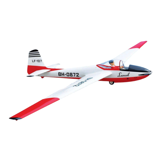
SPECIFICATION
Wingspan:
Length :
Weight :
Parts listing required (not included).
Radio :
Servo :
Electric motor: BOOST 180BL Motor
Battery: 12S - LIPO - 44.4V - 6,000mAh.HV
Speed control: 120A
Including Aluminium bubble wing bag and fuselage bag, elevator-rudder bag and glider cart.
Instruction Manual book
6,000mm
2,800 mm
18.5 kg
07-08 channels.
09-10
standard high torque servos.
236.22 in.
110.24 in.
40.7 Lbs.
ITEM CODE:BH 145
Made in Vietnam.
Advertisement
Table of Contents

Subscribe to Our Youtube Channel
Related Manuals for Black Horse Model LF-107 Lunak


Summary of Contents for Black Horse Model LF-107 Lunak
- Page 1 Instruction Manual book ITEM CODE:BH 145 SPECIFICATION Wingspan: 6,000mm 236.22 in. Length : 2,800 mm 110.24 in. Weight : 18.5 kg 40.7 Lbs. Parts listing required (not included). ...
-
Page 2: Parts List
LF-107 LUNAK Instruction Manual - Item code: BH145 This instruction manual is designed to help you build a great flying aeroplane. Please read this LF-107 LUNAK. manual thoroughly before starting assembly of your Use the parts listing below to identify all parts. -
Page 3: Safety Precaution
LF-107 LUNAK Instruction Manual - Item code: BH145 Caution: this model is not a toy! If you are a beginner to this type of powered model, please ask an experienced model flyer for help and support. If you attempt to operate the model without knowing what you are doing you could easily injure yourself or somebody else. - Page 4 LF-107 LUNAK Instruction Manual - Item code: BH145 REPLACEMENT LARGE PARTS F2. Aluminium tube wing Fuselage. A .Fuselage.A1,A2 F3. Aluminium tube wing B. Left Wing panel (B1,B2). B. Right Wing panel (C1,C2). F4. Aluminium tube wing F5. Aluminium tube Horizontal stabilizer.
- Page 5 LF-107 LUNAK Instruction Manual - Item code: BH145 I. AILERON1. Servo tray. 1.INSTALLING THE AILERON SERVOS1. 1) Install the rubber grommets and brass eyelets onto the aileron servos. Top side Bottom side Secure. 2) Using a modeling knife, remove the cov- ering at possition show below.
-
Page 6: Installing The Aileron Linkages
LF-107 LUNAK Instruction Manual - Item code: BH145 INSTALLING THE AILERON CONTROL HORN. Aileron control horn 5. Instal servo tray with aileron servo into the wing as same as picture below. A+B Epoxy PLUS glue 3x12mm. Secure. Aileron control... - Page 7 LF-107 LUNAK Instruction Manual - Item code: BH145 3x12mm 3x15mm Secure. Secure. Drill a hole 2.5mm diameter 3x12mm Secure. Bottom side.
-
Page 8: Installing The Aileron Servo
LF-107 LUNAK Instruction Manual - Item code: BH145 Secure 4x12mm Bottom side. Repeat the procedure for the other wing half. II.AILERON 2 1.INSTALLING THE AILERON SERVO 2 Top side. Bottom side. Aileron Flap... - Page 9 LF-107 LUNAK Instruction Manual - Item code: BH145 3x10mm Secure. Aileron. servo tray. 2.INSTALLING THE AILERON CONTROL HORN. Install flap control horn as same as picture below. Control horn aileron Electric wire. A+B Epoxy PLUS glue...
-
Page 10: Installing The Flap Servos
LF-107 LUNAK Instruction Manual - Item code: BH145 Control aileron. 3.INSTALLING THE AILERON LINKAGES. Installing the flap linkages as pictures below. 75 mm. 3x15mm 3x15mm. Secure. aileron Bottom side II. FLAP. 1.INSTALLING THE FLAP SERVOS. Bottom side Secure. Flap... - Page 11 LF-107 LUNAK Instruction Manual - Item code: BH145 2.INSTALLING THE FLAP CONTROL HORN. Install flap control horn as same Servo tray as picture below. Control horn Flap. Electric wire A+B Epoxy glue. 3X12mm Control horn of the flap 3.INSTALLING THE FLAP LINKAGES.
- Page 12 LF-107 LUNAK Instruction Manual - Item code: BH145 3x15mm. Left Bottom side. Secure. Flap Aileron Right Bottom side. Secure. INSTALLING THE FUSELAGE. See pictures below: 25mm 650mm Bottom side. Flap...
- Page 13 LF-107 LUNAK Instruction Manual - Item code: BH145 Wing bolt. Secure. Secure. Top side. INSTALLING ELECTRIC MOTOR AND ESC (Not included) See pictures below: 6x45 mm...
- Page 14 LF-107 LUNAK Instruction Manual - Item code: BH145 Front view. Drill a hole 5.2mm diameter. Open 4x20mm. 4x20mm S e c u r e 4x20mm 4x20mm.
- Page 15 LF-107 LUNAK Instruction Manual - Item code: BH145 Mottor Rotor shaft 3x12 mm Secure. Bettery Battery Front view Secure...
- Page 16 LF-107 LUNAK Instruction Manual - Item code: BH145 HORIZONTAL STABILIZER. ELEVATOR SERVO INSTALLATION. 1. Install the rubber grommets and brass collets into the elevator servo. Test fit the servo into the servo tray. 2. Mount the servo to the tray using the mounting screws provided with your radio system.
-
Page 17: Elevator Pushrod Installation
LF-107 LUNAK Instruction Manual - Item code: BH145 ELEVATOR CONTROL HORN STALLATION. Elevator control horn install as same as the way of aileron control horn. Please see pic- tures below. Control horn of elevator. A+B Epoxy PLUS glue. 3x 10mm... - Page 18 LF-107 LUNAK Instruction Manual - Item code: BH145 4x12mm: 3x15mm: Bottom side E l e v a t o r pushrod Left side. R i g h t side. E l e v a t o r pushrod 12mm 470mm...
- Page 19 LF-107 LUNAK Instruction Manual - Item code: BH145 Left side. Secure. Right side. Bottom side.
-
Page 20: Rudder Installation
LF-107 LUNAK Instruction Manual - Item code: BH145 RUDDER INSTALLATION. 4x12mm Rudder servo install as same as method of elevator servo. See picture below: R u d d e r servo Secure. R u d d e r servo VERTICAL INSTALLATION 12mm. - Page 21 LF-107 LUNAK Instruction Manual - Item code: BH145 Push. Top side. Secure. Aluminium Rudder. A l u - minium.
-
Page 22: Rudder Control Horn Installa- Tion
LF-107 LUNAK Instruction Manual - Item code: BH145 RUDDER CONTROL HORN INSTALLA- TION. A+B Epoxy Rudder control horn install as same as the PLUS glue way of aileron control horn. Please see pic- tures below. Control horn of Rudder. Top side A+B Epoxy PLUS glue Top side. -
Page 23: Rudder Cable Installation
LF-107 LUNAK Instruction Manual - Item code: BH145 RUDDER CABLE INSTALLATION. 3x12mm 1. Rudder push - pull system install as same as picture below. 3x15mm Secure Bottom side. Secure. - Page 24 LF-107 LUNAK Instruction Manual - Item code: BH145 Bottom side. Top side. C/A glue. Plastic parts top side Bottom side. pushrod. Elevator Elevator pushrod. pushrod. Rudder Rudder cable. cable. INSTALLING THE ESC-RECEIVER AND BAT- TERY. ...
-
Page 25: Wing Attachment
LF-107 LUNAK Instruction Manual - Item code: BH145 4. Using a 2mm drill bit, drill a hole through WING ATTACHMENT. the side of the fuselage, near the receiver, for Locate the aluminium wing dihedral brace. -
Page 26: Wing Joining
LF-107 LUNAK Instruction Manual - Item code: BH145 Wing bolt. Secure Wing bolt. Right wing. Secure. 3.Insert two wing panels as pictures below. WING JOINING. 19 mm 690 mm 19 mm 358 mm See picture wing attach to fuselage. - Page 27 LF-107 LUNAK Instruction Manual - Item code: BH145 Top side 4x15mm Top side Right side Secure. Bottom side Left side. Secure.
- Page 28 LF-107 LUNAK Instruction Manual - Item code: BH145 BALANCING. Right side. 1) It is critical that your airplane be bal- anced correctly. Improper balance will cause your plane to lose control and crash. THE CENTER OF GRAVITY IS LOCATED 164 MM BACK FROM THE LEADING EDGE OF THE WING.
-
Page 29: Control Throws
LF-107 LUNAK Instruction Manual - Item code: BH145 CONTROL THROWS. PRE-FLIGHT CHECK. 1) We highly recommend setting up a plane 1) Completely charge your transmitter and using the control throws listed.
Need help?
Do you have a question about the LF-107 Lunak and is the answer not in the manual?
Questions and answers