Table of Contents
Advertisement
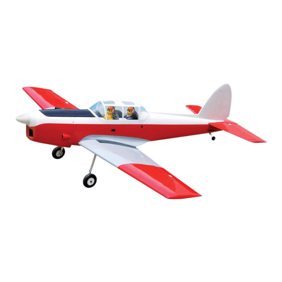
SPECIFICATION
Wingspan
Length
Weight
Servo
Radio
Engine
Electric motor: Rim Fire.60
Battery: 5-6cells -Li-Poly-18.5-22.2V -5.000mAh.
ESC : 80A
INSTRUCTION MANUAL BOOK.
:
1,630 mm
:
1,320 mm
:
3.3-3.5kg
:
07-08 servos.
:
06channels.
:
55- 61 cu.in-2 stroke.
91 cu.in-4 stroke.
ITEM CODE: BH44.
64.17in.
51.97 in.
7.26-7.70 lbs.
Made in Vietnam.
Advertisement
Table of Contents

Related Manuals for Black Horse Model CHIPMUNK BH44


Summary of Contents for Black Horse Model CHIPMUNK BH44
- Page 1 INSTRUCTION MANUAL BOOK. ITEM CODE: BH44. SPECIFICATION Wingspan 1,630 mm 64.17in. Length 1,320 mm 51.97 in. Weight 3.3-3.5kg 7.26-7.70 lbs. Servo 07-08 servos. 06channels. Radio 55- 61 cu.in-2 stroke. Engine 91 cu.in-4 stroke. Electric motor: Rim Fire.60 ...
- Page 2 CHIPMUNK INSTRUCTION MANUAL. -Item code BH44. This instruction manual is designed to help you build a great flying aeroplane. Please read this manual thoroughly before starting assembly of your CHIPMUNK. Use the parts listing below to identify all parts. WARNING. Please be aware that this aeroplane is not a toy and if assembled or used incorrectly it is capable of causing injury to people or property.
-
Page 3: Safety Precaution
CHIPMUNK INSTRUCTION MANUAL. -Item code BH44. Caution: this model is not a toy! If you are a beginner to this type of powered model, please ask an experienced model flyer for help and support. If you attempt to operate the model without knowing what you are doing you could easily injure yourself or somebody else. - Page 4 CHIPMUNK INSTRUCTION MANUAL. -Item code BH44. REPLACEMENT LARGE PARTS D. Horizontal stabilizer. G. Decal sheets. A. Cowling. B. Wing panel (Right & Left). F1. Aluminium tube wing. C. Fuselage. F2. Aluminium tube for Horizontal stabilizer. REPLACEMENT SMALL PARTS 35x25mm 4x25mm 5x35mm 5x35mm 5x35mm...
-
Page 5: Installing The Aileron- Flap Servos
CHIPMUNK INSTRUCTION MANUAL. -Item code BH44. INSTALLING THE AILERON- FLAP SERVOS. Bottom side. 1. Install the rubber grommets and brass eyelets onto the aileron and flap servo. Aileron. Flap. 2. Using a modeling knife, remove the cov- ering servo tray. Bottom side. - Page 6 CHIPMUNK INSTRUCTION MANUAL. -Item code BH44. 3. Drill 1,5mm pilot holes through the block of wood for each of the four mounting screws provided with the servo. Install servo into ai- Secure leron servo tray as same as picture below. Secure INSTALLING THE AILERON CONTROL HORN.
-
Page 7: Installing The Aileron Linkages
CHIPMUNK INSTRUCTION MANUAL. -Item code BH44. 4. Locate one nylon servo arm, and using wire cutters,remove all but one of the arms. Using a 2mm drill bit, enlarge the third hole out from the center of the arm to accommo- date the aileron pushrod wire. -
Page 8: Installing The Flap Servos
CHIPMUNK INSTRUCTION MANUAL. -Item code BH44. Electric wire. Thread. Aileron. Repeat the procedure for the other wing half. II. FLAP. 1.INSTALLING THE FLAP SERVOS. servo tray with flap .Install servo in to the wing as same as picture below. 2x10mm. Flap. - Page 9 CHIPMUNK INSTRUCTION MANUAL. -Item code BH44. 2.INSTALLING THE FLAP CONTROL HORN. Flap Install control horn as same as picture below as same as the way of aileron. Bend. Flap control horn Flap. A+B Epoxy PLUS glue Flap. Cut. Flap control . Flap.
-
Page 10: Installing Landing Gear
CHIPMUNK INSTRUCTION MANUAL. -Item code BH44. Bottom side Aileron Flap Repeat the procedure for the other wing half. INSTALLING LANDING GEAR. 3x15mm 5x35mm 5x35mm Mark point and drill a hole 3x15mm 2mm. A+B Epoxy PLUS A+B Epoxy PLUS glue. Secure. -
Page 11: Engine Mount
CHIPMUNK INSTRUCTION MANUAL. -Item code BH44. 5x35mm Secure. Bottom side. Repeat the procedure for the other gear half. ENGINE MOUNT. See pictures below: 3.5x25mm. Secure. 4x25mm. -
Page 12: Installing The Engine
CHIPMUNK INSTRUCTION MANUAL. -Item code BH44. INSTALLING THE ENGINE. Locate the long piece of wire used for the throttle pushrod. One end of the wire has been pre-bend in to a “Z” bend at the factory . This “Z” bend should be inserted into the throttle arm of the engine when the engine is fitted onto the engine mount. -
Page 13: Installing The Stopper Assembly
CHIPMUNK INSTRUCTION MANUAL. -Item code BH44. Pushrod wire. FUEL TANK. INSTALLING THE STOPPER ASSEMBLY 1. The stopper has been pre-assembled at the factory. 2. Using a modeling knife, cut one length of silicon fuel line (the length of silicon fuel line is calculated by how the weighted clunk should rest about 8mm away from the rear of the tank and move freely inside the tank). - Page 14 CHIPMUNK INSTRUCTION MANUAL. -Item code BH44. Silicon not included. 5. Test fit the stopper assembly into the tank. It may be necessary to remove some of Do not secure the tank into place perma- the flashing around the tank opening using nently until after balancing the airplane.
-
Page 15: Installing The Throttle Pushrod
CHIPMUNK INSTRUCTION MANUAL. -Item code BH44. After installing the adjustable metal con- nector apply a small drop of thin C/A to the bottom nut. This will prevent the con- nector from loosening during flight. Throttle servo Tie wrap. secure. INSTALLING THE THROTTLE PUSHROD. 1. - Page 16 CHIPMUNK INSTRUCTION MANUAL. -Item code BH44. COWLING. Left side. 1. Slide the fiberglass cowl over the en- gine and line up the back edge of the cowl with Right side the marks you made on the fuselage. 2. While keeping the back edge of the cowl flush with the marks, align the front of the cowl with the crankshaft of the engine.
-
Page 17: Installing The Spinner
CHIPMUNK INSTRUCTION MANUAL. -Item code BH44. INSTALLING THE SPINNER. Install the spinner backplate, propeller and spinner cone. The spinner cone is held in place using two 3mm x 12mm machine screws. 3x12mm Secure. M a c h i n e screw. - Page 18 CHIPMUNK INSTRUCTION MANUAL. -Item code BH44. HORIZONTAL STABILIZER, VESTICAL INSTALLATION. Secure Horizontal stabilize installation . See picture below. ELEVATOR INSTALLATION. SERVO INSTALLATION. 1. Install the rubber grommets and brass collets into the elevator servo. Test fit the servo into the servo tray.
- Page 19 CHIPMUNK INSTRUCTION MANUAL. -Item code BH44. Epoxy glue Aluminium tube 9mm 193mm Epoxy glue...
-
Page 20: Elevator Pushrod Installation
CHIPMUNK INSTRUCTION MANUAL. -Item code BH44. C/A glue Top side. Control horn of elevator . Bottom side. ELEVATOR PUSHROD INSTALLATION. Elevator pushrod install as same as the way of aileron pushrod. M2 lock nut. ELEVATOR CONTROL HORN INSTALLA- TION. Elevator control horn install as same as the way of aileron control horn. -
Page 21: Rudder Servo Installation
CHIPMUNK INSTRUCTION MANUAL. -Item code BH44. Elevator pushrod. Bend 90 degrees. Snap keeper. RUDDER SERVO INSTALLATION. Rudder servo install as same as method of elevator servo. See picture below: Rudder servo. -
Page 22: Mounting The Tail Wheel Bracket
CHIPMUNK INSTRUCTION MANUAL. -Item code BH44. MOUNTING THE TAIL WHEEL BRACKET. 3x10mm 3 X 10 mm. 1. Set the tail wheel assembly in place on the plywood plate. The pivot point of the tail wheel wire should be even with the rud- Secure. - Page 23 CHIPMUNK INSTRUCTION MANUAL. -Item code BH44. RUDDER CONTROL HORN THE INSTALLATION. Rudder Rudder control horn pushrod Secure. Top side. Rudder Rudder control horn pushrod Bottom side. Elevator Elevator pushrod. pushrod.
- Page 24 CHIPMUNK INSTRUCTION MANUAL. -Item code BH44. A+ B Epoxy PLUS glue. Cut the covering away from the slot. Mark made. 29mm Temporary pin to keep hinge centered. Bend 90 degree. Assemble then apply drops of thin C/A to center of hinge,on both sides. Cut.
-
Page 25: Rudder Pushrod Installa- Tion
CHIPMUNK INSTRUCTION MANUAL. -Item code BH44. C/A glue Top side. cut. RUDDER PUSHROD INSTALLA- TION. Rudder servo. Rudder pushrod Bend. -
Page 26: Installing The Switch
CHIPMUNK INSTRUCTION MANUAL. -Item code BH44. Bottom side. Top side. Rudder pushrod Elevator pushrod Elevator pushrod INSTALLING THE SWITCH. Plastic parts of elevator 1) Cut out the switch hole using a modeling pushrod. knife. Use a 2mm drill bit and drill out the two mounting holes through the fuselage side. -
Page 27: Wing Attachment
CHIPMUNK INSTRUCTION MANUAL. -Item code BH44. Do not permanently secure the receiver and battery until after balancing the model. 4. Using a 2mm drill bit, drill a hole through the side of the fuselage, near the receiver , for the antenna to exit. - Page 28 CHIPMUNK INSTRUCTION MANUAL. -Item code BH44. Insert and secure Top side. Secure BALANCING. 1. It is critical that your airplane be bal- anced correctly. Improper balance will cause your plane to lose control and crash. THE CENTER OF GRA VITY IS LOCA TED Secure 95mm BACK FROM THE LEADING EDGE...
-
Page 29: Control Throws
CHIPMUNK INSTRUCTION MANUAL. -Item code BH44. With the wing attached to the fuselage, all CONTROL THROWS. parts of the model installed ( ready to fly), and 1. We highly recommend setting up a plane empty fuel tanks, hold the model at the ...
Need help?
Do you have a question about the CHIPMUNK BH44 and is the answer not in the manual?
Questions and answers