Table of Contents
Advertisement
Quick Links
SPECIFICATION
Wingspan :
Length
Weight
Parts listing required(not included).
Radio
Servo
Electric motor: Power Plant size 40.
Battery :3S-LIPo-11.1V-3,250mAh
Speed control : 60A
Propeller : 14x8 folding.
Instruction Manual book
2,700mm
:
1,410 mm
:
2.5kg
: 06 channels.
: 07 mini servos.
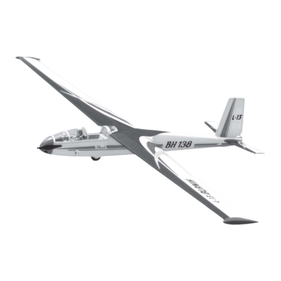
ITEM CODE:BH 138
106.30 in.
55.51 in.
5.50 Lbs.
Made in Vietnam.
Advertisement
Table of Contents

Related Manuals for Black Horse Model L-13 Blanik


Summary of Contents for Black Horse Model L-13 Blanik
- Page 1 Instruction Manual book ITEM CODE:BH 138 SPECIFICATION Wingspan : 2,700mm 106.30 in. Length 1,410 mm 55.51 in. Weight 2.5kg 5.50 Lbs. Parts listing required(not included). ...
-
Page 2: Parts List
L-13 BLANIK Instruction Manual Item code: BH138 This instruction manual is designed to help you build a great flying aeroplane. Please read this L-13 BLANIK. manual thoroughly before starting assembly of your Use the parts listing below to identify all parts. -
Page 3: Safety Precaution
L-13 BLANIK Instruction Manual Item code: BH138 Caution: this model is not a toy! If you are a beginner to this type of powered model, please ask an experienced model flyer for help and support. If you attempt to operate the model without knowing what you are doing you could easily injure yourself or somebody else. -
Page 4: Installing The Aileron Servos
L-13 BLANIK Instruction Manual Item code: BH138 REPLACEMENT LARGE PARTS A. Fuselage. Top side B. Wing panel(B1,B2). C.Horizontal stabilizer(C1,C2). D. Vertical stabilizer. E. Aluminium tube wing dihedral brace. Bottom side. F1.Aluminium tube Horizontal stabilizer. F2.Aluminium tube vertical stabilizer. Aileron G. Decal sheet. - Page 5 L-13 BLANIK Instruction Manual Item code: BH138 3) Using the thread as a guide and using Bottom side. masking tape, tape the servo lead to the end of the thread: carefully pull the thread out. When you have pulled the servo lead out, re- move the masking tape and the servo lead ...
-
Page 6: Installing The Aileron Linkages
L-13 BLANIK Instruction Manual Item code: BH138 INSTALLING THE AILERON CONTROL HORN. Install aileron control horn as same as picture below. Aileron control horn A+B Epoxy PLUS glue Bottom side Aileron. Repeat the procedure for the other wing half. II. FLAP 1.INSTALLING THE FLAP SERVO... - Page 7 L-13 BLANIK Instruction Manual Item code: BH138 2.INSTALLING THE FLAP CONTROL HORN. Install flap control horn as same as pic- ture below. Control horn Flap. thread A+B Epoxy Electric PLUS glue wire. 2x10mm. Control horn of the flap. Secure. 3.INSTALLING THE FLAP LINKAGES.
- Page 8 L-13 BLANIK Instruction Manual Item code: BH138 Secure. Left bottom side. Right bottom side. INSTALLING ELECTRIC MOTOR. See pictures below: 4x12mm Drill a hole 3.8mm diameter.
- Page 9 L-13 BLANIK Instruction Manual Item code: BH138 Rotor shaft Motor Secure. Secure. Motor Rotor shaft Secure.
-
Page 10: Installing Propeller
L-13 BLANIK Instruction Manual Item code: BH138 ELEVATOR SERVO INSTALLATION. 1. Install the rubber grommets and brass collets into the elevator servo. Test fit the servo into the servo tray. 2. Mount the servo to the tray using the mounting screws provided with your radio sys- tem. - Page 11 L-13 BLANIK Instruction Manual Item code: BH138 Right side Cut the covering away from the slot. Carbon tube. Temporary pin to keep hinge centered. Right side stabilizer horizontal. Assemble then apply drops of thin C/A to center of hinge,on both sides.
-
Page 12: Elevator Control Horn Installation
L-13 BLANIK Instruction Manual Item code: BH138 C/A glue. C/A glue. ELEVATOR CONTROL HORN INSTALLATION. Elevator control horn install as same as the way of aileron control horn. Please see pic- tures below. Control horn of elevator. Left side stabilizer horizontal. -
Page 13: Elevator Pushrod Installation
L-13 BLANIK Instruction Manual Item code: BH138 Bottom side E l e v a t o r control E l e v a t o r control. ELEVATOR PUSHROD INSTALLATION. Elevator pushrod install as same as the way of aileron pushrod. -
Page 14: Rudder Servo Installation
L-13 BLANIK Instruction Manual Item code: BH138 RUDDER SERVO INSTALLATION. Assemble then apply drops of thin C/A to center of hinge,on both sides. Rudder servo install as same as method of elevator servo. See picture below: Rudder servo VERTICAL INSTALLATION. -
Page 15: Rudder Control Horn Installa- Tion
L-13 BLANIK Instruction Manual Item code: BH138 Right side. RUDDER CONTROL HORN INSTALLA- TION. Rudder control horn install as same as the way of aileron control horn. Please see pic- tures below. Control horn of Rudder. A+B Epoxy PLUS glue. -
Page 16: Rudder Pushrod Installation
L-13 BLANIK Instruction Manual Item code: BH138 Bottom side. Bend and cut after Rudder control horn RUDDER PUSHROD INSTALLATION. Rudder pushrod install as same as the way of aileron pushrod. M2 lock nut. -
Page 17: Mounting The Tail Wheel Bracket
L-13 BLANIK Instruction Manual Item code: BH138 R u d d e r pushrod. 3. Secure the tail wheel bracket in place using three 3mm x 10mm wood screws. Be careful not to overtighten the screws. -
Page 18: Wing Attachment
L-13 BLANIK Instruction Manual Item code: BH138 2. Wrap the receiver and battery pack in the protective foam to protect them from vi- bration. Use a rubber band or masking tape to hold the foam in place. -
Page 19: Installing Cockpit Fuselage
L-13 BLANIK Instruction Manual Item code: BH138 2. Attach the aluminium tube into the fuselage. Right side. Secure INSTALLING COCKPIT FUSELAGE . See picture below: 3.Insert two wing panels as pictures below. Letf side. A+B Epoxy PLus glue... - Page 20 L-13 BLANIK Instruction Manual Item code: BH138 BALANCING. 1) It is critical that your airplane be bal- anced correctly. Improper balance will cause your plane to lose control and crash. THE CENTER OF GRAVITY IS LOCATED 27MM BACK FROM THE LEADING EDGE OF THE WING.
-
Page 21: Control Throws
6) Properly balance the propeller. 14 mm We wish you many safe and enjoy- 14 mm able flights with your L-13 BLANIK. Aileron control 25 mm Flap control 12 mm 12 mm Elevator control...
Need help?
Do you have a question about the L-13 Blanik and is the answer not in the manual?
Questions and answers