Table of Contents
Advertisement
Quick Links
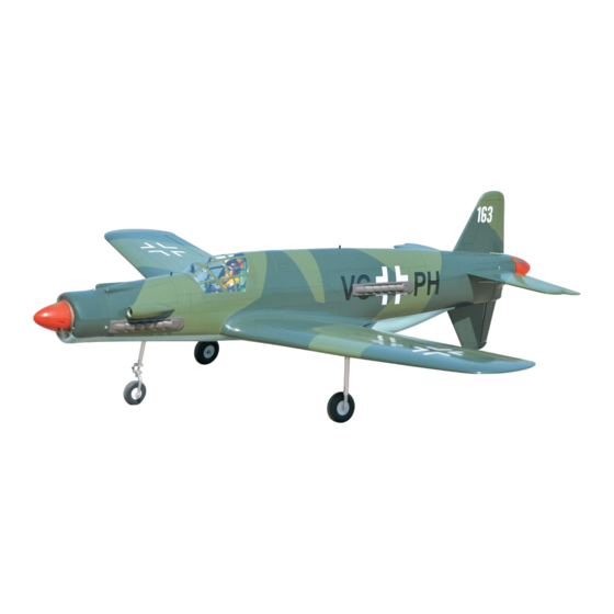
DORNIER DO335
NOT INCLUDING ELECTRIC GEAR RETRACTS.
ONLY INCLUDING OLEO STRUTS.
ALL BALSA - PLY WOOD CONSTRUCTION.
COVERED IN A HEAT-SHRINK FILM WITH PRINTED.
95% ALMOST READY TO FLY
SPECIFICATION:
- Wingspan: 1,724mm (67.87in).
- Length: 1,731mm (68.15 in).
- Weight: 6 kg (13.2lbs).
- Wing area: 61.4dm .
- Wing loading: 97.72g/dm .
- Wing type: Naca Airfoil.
- Servo mount: 42mm x 21mm.
- Gear type: Electric retract gear,
size: (92.2 x 51 x 30.6)mm (not included).
Oleo struts (included).
- Spinner (2pcs): 80mm.
Instruction Manual Book
2
2
Item code: BH163.
Parts listing required (not included):
- Radio: 06 channels.
- Servo: 07 servos.
- Motor (2pcs) : Brushless outrunner 1000-1800W, 800KV.
- Propeller (2pcs): Suit with your engine.
Recommended Motor
and battery set up (not included):
- Motor (2pcs): RIMFIRE.55
- Lipo cell: 6 cells 5,000mAh.
- ESC (2pcs) : 60A.
Made in Vietnam.
Advertisement
Table of Contents

Related Manuals for Black Horse Model dornier DO335


Summary of Contents for Black Horse Model dornier DO335
- Page 1 Instruction Manual Book Item code: BH163. DORNIER DO335 NOT INCLUDING ELECTRIC GEAR RETRACTS. ONLY INCLUDING OLEO STRUTS. ALL BALSA - PLY WOOD CONSTRUCTION. COVERED IN A HEAT-SHRINK FILM WITH PRINTED. 95% ALMOST READY TO FLY SPECIFICATION: - Wingspan: 1,724mm (67.87in).
- Page 2 DORNIER DO335 Item code: BH163 This instruction manual is designed to help you build a great flying aeroplane. Please read this manual thoroughly DORNIER DO335 before starting assembly of your . Use the parts listing below to identify all parts.
-
Page 3: Tools And Supplies Needed
DORNIER DO335 Item code: BH163 TOOLS & SUPPLIES NEEDED EPOXY A EPOXY B Epoxy Glue (5 minute type). Hand or electric drill. Epoxy Glue (30 minute type). Threadlocker (screw cement). Hobby knife. Some more tools. Awl. Assorted drill bits. Phillips head screwdriver. - Page 4 DORNIER DO335 Item code: BH163 : Fuselage. : Wing panel ( 2a, 2b . : Horizontal stabilizer (3a, 3b). : Rudder (4a, 4b). : Aluminium wing dihedral brace. : Cowling (6a, 6b). : Spinner. : Air intake. : Cockpit fuselage (9a : Canopy, 9b : Pilot, 9c : Cockpit).
- Page 5 DORNIER DO335 Item code: BH163 * Apply drops of thin CA to the top and bottom of each 1. INSTALLING THE AILERONS, FLAPS hinge. Do not use CA accelerator. After the CA has fully hardened, test the hinges by pulling on the aileron.
- Page 6 DORNIER DO335 Item code: BH163 3. INSTALLING THE CONTROL HORNS, LINKAGES Insert the 90 degree bend down through the hole in the 5mm Silicone Tube control horn. Install one nylon snap keeper over the - - - - - 4...
- Page 7 DORNIER DO335 Item code: BH163 1) Slide the fiberglass cowl over the motor and line up the back edge of the cowl with the marks you made on the fuselage. 2) While keeping the back edge of the cowl flush with the marks, align the front of the cowl with the crankshaft of the motor.
-
Page 8: Installing The Fuselage Servos
DORNIER DO335 Item code: BH163 Drill four 2.5mm pilot holes through both side of the cowl and the side edges of the firewall. Using a 3mm drill bit, enlarge the four holes in the cowling. 3x12mm. Secure 5. INSTALLING THE FUSELAGE SERVOS... -
Page 9: Rudder Installation
DORNIER DO335 Item code: BH163 6. RUDDER INSTALLATION Rudder control horn Rudders are installed the same way as the aileron before (see page 5). Rudder pushrod Rudder Epoxy glue Silicone Tube Rudder Fuselage top side RUDDER CONTROL HORN, PUSHROD INSTALLATION... -
Page 10: Installing The Wheel Well
DORNIER DO335 Item code: BH163 Fuselage top side Attach the stabilizer Fuselage bottom side to the fuselage. 3) Elevator c ontrol horns, linkages are installed the same way as the aileron before (see page 6). Fuselage top side Fuselage bottom side... -
Page 11: Installing Main Gear
DORNIER DO335 Item code: BH163 Fuselage bottom view C/A glue 9. INSTALLING MAIN GEAR 3x15mm Screw - - - - - - 8 5 x 35mm Cap Screw - - - - - - 2 5mm Colar - - - - - - 2 85mm Wheels. - Page 12 DORNIER DO335 Item code: BH163 OPTION 2: ELECTRIC GEAR RETRACTS Electric not included. 43.70 30.70 92.20 24.10 21.00 48.50 Apply threadlocker 5mm Collar Secure 5x35mm 5mm Washer 3x15mm Secure Secure Repeat the procedure to install the opposite gear.
-
Page 13: Installing The Nose Gear
DORNIER DO335 Item code: BH163 10. INSTALLING NOSE GEAR 3 x 15mm Screw 5mm Colar - - - - - - - 1 - - - - - - 4 - - - - - - - - 4 Spring... -
Page 14: Wing Attachment
DORNIER DO335 Item code: BH163 Install two cable to the steering servo nose gear. Fuselage top side M2 Clevis 11. INSTALLING THE RECEIVER, ESC AND BATTERY 1) Plug the servo leads and the switch lead into the 4) Using a 2mm drill bit, drill a hole through the side of receiver. -
Page 15: Installing Cockpit Fuselage
DORNIER DO335 Item code: BH163 Fuselage b ottom side. Insert the wing panel as pictures below. Screw the wing panel in position. Secure Secure 13. INSTALLING COCKPIT FUSELAGE Fuselage top side A+B Epoxy glue. Open/close Open/close Position the canopy so the rear... - Page 16 DORNIER DO335 Item code: BH163 Adhesive tape. 14. PLASTIC PARTS OF FUSELAGE Fuselage top side. C/A glue C/A glue C/A glue Air intake C/A glue C/A glue Fuselage b ottom side. C/A glue Air intake...
-
Page 17: Installing The Spinner, Propeller
DORNIER DO335 Item code: BH163 Fuselage top side. 15. INSTALLING THE SPINNER, PROPELLER Secure - - - - - - 8 Secure... -
Page 18: Control Throws
DORNIER DO335 Item code: BH163 BALANCING CONTROL THROWS 1) It is critical that your airplane be balanced correctly. 1) We highly recommend setting up a plane using the Improper balance will cause your plane to lose control control throws listed. - Page 19 DORNIER DO335 Item code: BH163 Motor Battery uggestion : Use a sharp secewdriver to take the red E.S.C cable out from (only one ESC) the BEC connector, and then insulate it with a bit of electrical tape for futher use.
- Page 20 I/C FLINGT WARNINGS Always operate in open areas, away from NEVER fly near power lines,aerials or ALWAYS adjust the engine from behind factories, hospitals, schools, buildings the propeller, and do not allow any part of other dangerous areas including airports, and houses etc.
Need help?
Do you have a question about the dornier DO335 and is the answer not in the manual?
Questions and answers