Table of Contents
Advertisement
Advertisement
Table of Contents

Subscribe to Our Youtube Channel
Related Manuals for Black Horse Model Landscape


Summary of Contents for Black Horse Model Landscape
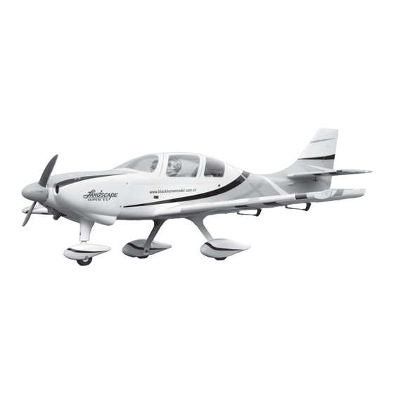
- Page 1 Instruction Manual book ITEM CODE:BH101. SPECIFICATION Wingspan : 1,940 mm 76.38 inches. Length : 1,700 mm 66.93 inches. Weight : 5.8 kg 12.76 lbs. Radio 6 channels.
-
Page 2: Tools & Supplies Needed
Instruction Manual Item code: BH101A This instruction manual is designed to help you build a great flying aeroplane. Please read this manual thoroughly before starting assembly of your LANDSCAPE. Use the parts listing below to identify all parts. WARNING. Please be aware that this aeroplane is not a toy and if assembled or used incorrectly it is capable of causing injury to people or property. -
Page 3: Safety Precaution
LANDSCAPE - Instruction Manual Item code: BH101A Caution: this model is not a toy! If you are a beginner to this type of powered model, please ask an experienced model flyer for help and support. If you attempt to operate the model without knowing what you are doing you could easily injure yourself or somebody else. - Page 4 LANDSCAPE - Instruction Manual Item code: BH101A 1. Aluminium landing gear. 2. Wheels. Bottom side. 3. Plastic part for nose gear. 4. Plastic parts for rudder pushrod. 5. Nose gear set. 6.Engine mount ply of wood . Aileron. Flap. 7. Plastic parts for landing gear.
-
Page 5: Installing The Aileron Linkages
LANDSCAPE - Instruction Manual Item code: BH101A Install aileron control horn as same as picture below. Secure. 4. Using the thread as a guide and using A+B Epoxy masking tape, tape the servo lead to the end PLUS glue. - Page 6 LANDSCAPE - Instruction Manual Item code: BH101A INSTALLING THE FLAP CONTROL HORN. INSTALLING THE FLAP SERVO. Control horn of Electric the flap. wire INSTALLING THE FLAP LINKAGES. Thread Installing the aileron linkages as pictures 75 mm 2x10mm. Secure.
- Page 7 LANDSCAPE - Instruction Manual Item code: BH101A Flap. Bottom side Repeat the procedure for the other wing half. INSTALLING THE ENGINE MOUNT NOSE GEAR. See pictures below: Drill a hole 4mm diameter.
- Page 8 LANDSCAPE - Instruction Manual Item code: BH101A wire cable. Secure. SERVO NOSE GEAR INSTALLATION. wire cable.
-
Page 9: Installing The Stopper Assembly
LANDSCAPE - Instruction Manual Item code: BH101A Secure. Secure FUEL TANK. INSTALLING THE STOPPER ASSEMBLY 1. The stopper has been pre-assembled at the factory. 2. Using a modeling knife, cut one length of silicon fuel line (the length of silicon fuel line is... - Page 10 LANDSCAPE - Instruction Manual Item code: BH101A 5. Test fit the stopper assembly into the tank. It may be necessary to remove some of the flashing around the tank opening using a modeling knife. If flashing is present, make sure none of it falls into the tank.
-
Page 11: Installing The Throttle Cable
LANDSCAPE - Instruction Manual Item code: BH101A Throttle cable. INSTALLING THE THROTTLE CABLE. Mount ply of wood . 3x12mm Throttle servo. Secure. Throttle cable. Right side... - Page 12 LANDSCAPE - Instruction Manual Item code: BH101A 2. While keeping the back edge of the cowl flush with the marks, align the front of the cowl with the crankshaft of the engine. The front of the cowl should be positioned so the crankshaft is in nearly the middle of the cowl opening.
-
Page 13: Installing The Spinner
LANDSCAPE - Instruction Manual Item code: BH101A C/A glue. Secure. MAIN GEAR INSTALATION. PARTS REQUIRED Front view. INSTALLING THE SPINNER. 1) Assemble and mounting the wheel pants Install the spinner backplate, propeller and as shown in the following pictures. - Page 14 LANDSCAPE - Instruction Manual Item code: BH101A Plastic parts for landing gear. R e m o v e covering. Secure. Cut. Secure. Landing gear. Silicon. Silicon.
-
Page 15: Installing The Elevator Servos
LANDSCAPE - Instruction Manual Item code: BH101A C/A glue Secure. Repeat the process for the other wheel. Mark line. Remove covering Bottom side. INSTALLING THE ELEVATOR SERVOS. Elevator servo Epoxy glue. 1. Install the rubber grommets and brass collets into the elevator servo. Test fit the servo into the servo tray. -
Page 16: Horizontal Stabilizer
LANDSCAPE - Instruction Manual Item code: BH101A HORIZONTAL STABILIZER. 3 x 12mm 3x12 mm. Secure. Secure. Aluminium 9 mm 282 mm ELEVATOR CONTROL HORN INSTALLA- TION. Elevator control horn install as same as the way of aileron control horn. Please see pic-... -
Page 17: Rudder Servos Installation
LANDSCAPE - Instruction Manual Item code: BH101A Elevator pushrod A+ B Epoxy PLUS glue Elevator Elevator pushrod pushrod Elevator Control horn. Elevator Control horn. ELEVATOR PUSHDROD INSTALLATION Elevator pushrod install as same as the way of aileron pushrod. RUDDER SERVOS INSTALLATION. -
Page 18: Rudder Control Horn Installa- Tion
LANDSCAPE - Instruction Manual Item code: BH101A Aluminium RUDDER SERVOS INSTALLATION. See pitures bellow. Cut. A+B Epoxy PLUS glue. RUDDER CONTROL HORN INSTALLA- TION. Rudder control horn install as same as the way of aileron control horn. Please see pic- tures below. -
Page 19: Rudder Pushrod Installation
LANDSCAPE - Instruction Manual Item code: BH101A A+B Epoxy PLUS glue Rudder pushrod Plastic parts of pushrod. Rudder control horn RUDDER PUSHROD INSTALLATION. 1. Rudder pushrod install as same as Cut. the way of aileron control horn. -
Page 20: Installing The Switch
LANDSCAPE - Instruction Manual Item code: BH101A INSTALLING THE SWITCH. 1. Cut out the switch hole using a modeling knife. Use a 2mm drill bit and drill out the two mounting holes through the fuselage side. -
Page 21: Wing Attachment
LANDSCAPE - Instruction Manual Item code: BH101A INSTALLING THE RECEIVER AND BATTERY. Receiver 1. Plug the servo leads and the switch lead into the receiver. You may want to plug an aileron extension into the receiver to make plugging in the aileron servo lead easier when you are installing the wing . - Page 22 LANDSCAPE - Instruction Manual Item code: BH101A Installing the fuselage hatch as same as picture below. UBEC. Secure. Top side Drill a hole diameter.er Drill a hole diameter.er 4 x 40mm Secure. Secure. Left wing. Top side...
-
Page 23: Control Throws
LANDSCAPE - Instruction Manual Item code: BH101A BALANCING. CONTROL THROWS. 1. We highly recommend setting up a plane 1. It is critical that your airplane be bal- anced correctly. Improper balance will cause using the control throws listed.
Need help?
Do you have a question about the Landscape and is the answer not in the manual?
Questions and answers