Table of Contents
Advertisement
FIT T E D E Q UIP ME N T
Truma Combination Boiler ...................................................................................................... 94
Truma Heating System And Air Flow .......................................................................................... 95
Truma CP 25 digital timer control ........................................................................................... 95
Truma Cp Plus Digital Timer Control ........................................................................................ 99
Truma Combination Boiler fault finding .................................................................................. 107
Truma Combi heating system function description ................................................................ 108
Alde Compact 3010 .......................................................................................................... 112
ALDE Compact 3010 Control Panel ...................................................................................... 117
Thetford Refrigerators ............................................................................................................ 125
Dometic absorption refrigerators ........................................................................................... 133
Cooker 3 burner and hotplate ............................................................................................... 154
Cooker 3 Burner Gas Hob (Sprite only) ................................................................................... 159
Microwave oven .................................................................................................................. 162
Thetford C260 Cassette Toilet ................................................................................................ 165
Caravans with external BBQ point ........................................................................................ 172
Caravans With Tv Inlet In Battery Box .................................................................................... 173
Status 550 directional TV and FM radio antenna .................................................................. 175
Bedding ................................................................................................................................ 176
Softrollo Blinds (Seitz) ........................................................................................................... 177
Doorscreen ........................................................................................................................... 177
Roof Lights ............................................................................................................................ 178
Exterior Door Key ................................................................................................................. 178
Windows .............................................................................................................................. 178
Heki-2 Roof Light (Seitz) .......................................................................................................... 179
Mini Heki Rooflight ................................................................................................................. 179
Care Of Laminate Tops, Tables, Furniture And Doors ................................................................. 179
Doors ................................................................................................................................... 179
Tables ................................................................................................................................... 180
Table Storage ........................................................................................................................ 180
12V Reading Lamp ................................................................................................................. 180
Trigger shower heads ............................................................................................................ 180
Fixing Of Awnings .................................................................................................................. 180
Paint colour reference ............................................................................................................ 181
Drop Down Tv Mechanism .................................................................................................... 181
Front Locker And Sunroof ........................................................................................................ 181
Bonded Roof ......................................................................................................................... 181
Step On Hitch Cover ............................................................................................................... 181
Cycle Racks ........................................................................................................................... 182
Caravan motor mover ............................................................................................................. 182
Omni-Vent ............................................................................................................................. 183
Rear view camera .................................................................................................................. 185
93
Advertisement
Table of Contents
Troubleshooting

Related Manuals for Truma Boiler


Summary of Contents for Truma Boiler
- Page 1 FIT T E D E Q UIP ME N T Truma Combination Boiler ...................... 94 Truma heating system and air flow ..................95 Truma CP 25 digital timer control ................... 95 Truma CP Plus digital timer control ..................99 Truma Combination Boiler fault finding .................. 107 Truma Combi heating system function description ..............
-
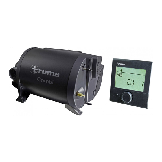
Page 2: Truma Combination Boiler
Operating on electric only may not in all cases maintain a comfortable room temperature especially in colder conditions. The intelligent heat management system in dual fuel mode allows the Truma Combination boiler to prioritize the electric power source over your gas, this will conserve your gas supply. -
Page 3: Control Panels
Butterfly outlets Operating instructions Depending on the specification of your caravan, the CP25 controller may be fitted to control the operation of the Truma Combi appliance. Please be sure to read the instructions for installation and use before attempting to... - Page 4 EG: Energy selection (E = Electro, G = Gas) Repairs W: Set water temperature Do not repair or modify the device. Please contact your dealer or the Truma Service (see service manual or www.truma.com). Accessories Only use accessories and additional devices that are supplied or recommended by the manufacturer.
- Page 5 Water temperature Note: A pre-selection between summer / winter operation must be made via the When the menu is selected the yellow LED set-up. shines. During the heating-up phase, the set water temperature flashes in the main screen. • Use key or to select the water Room Temperature temperature and confirm with SET.
- Page 6 Device does not react anymore Interrupt power supply for 10 seconds Heater / display does not react Check 12 V supply voltage If these measures do not rectify the problem, please contact the next Truma service point (See Truma service book or www.truma.com)
-
Page 7: Truma Cp Plus Digital Timer Control
Truma CP Plus Digital Timer Control Depending on the specification of your caravan, the Truma CP-Plus controller may be fitted to control the operation of the Truma Combi appliance. Safety instructions • The device may only be operated if it is in perfect working order. - Page 8 T R U M A CP P LU S DIG I TAL TIM E R CON T ROL Display and control elements Turn to the left (-) • Menu is paged from right to left. • Reduce values. Clicking • Accept (save) a selected value.
- Page 9 • Click the control knob / push button to confirm the value. a = Boiler * (Warm water boiler is switched on) b = 40° (Warm water temperature 40 °C) c = 60° (Warm water temperature 60 °C)
- Page 10 (Targeted, fast heating of the content of the Malfunction in the combustion process boiler [boiler priority]. The water temperature (e.g. lack of fuel) is kept at the higher level [around 62 °C] – Not Combi Gas Combi Diesel.
- Page 11 Symbol Operating mode Description – Fan is switched off Circulating air, if no device is in operation. 9 speed levels can Vent be selected. Low fan level High fan level (only Combi Gas) Fast heating of the room. Available, if the difference between High the selected and current room temperature is >10 °C.
-
Page 12: Set Time
T R U MA C P P L U S DI G ITAL TI M ER CON T ROL Select power type Deactivate the timer (OFF) • Click to change to the setting level. • Click to change to the setting level. •... - Page 13 Service menu Warning Query the index status of a In the event of a warning, a warning symbol connected device appears to indicate that an operating parameter has reached an undefined status. In this case, the affected device continues to run. As soon as the operating parameter returns to the set range, this symbol will turn off automatically.
- Page 14 T R U MA C P P L U S DI G ITAL TI M ER CON T ROL Malfunctions In the case of a malfunction, the control panel immediately jumps to the menu level “malfunction” and shows the error code of the malfunction: Cause remedied / return to setting level •...
- Page 15 • Use propane (Butane is unsuitable cylinder for heating, especially at tempera- tures below 10 • Room temperature sensor or • Please contact the Truma Service cable faulty • Potential under-voltage battery • Charge battery voltage too low <10.4V • Heating element for FrostControl •...
- Page 16 The liquid gas heater Combi E is a warm-air temperature can be set to 40 °C or 60 °C. heater with integrated hot water boiler (10 liter With gas operation the water is heated at volume). The burner operates fan-supported, the lowest burner setting.
- Page 17 (set up to 70 °C. preselecting mixing taps or single-lever fittings to “hot”). Leave the fittings open for as long as it takes for the boiler to displace the air and fill up, and the water to flow without interruption.
- Page 18 TR U MA C OMB I B OI LER Fuses 12 V Overheating protection 230 V The fuse is in the electronics beneath the The 230 V heating facility has a mechanical connection cover. Replace the unit’s fuse only overheating switch. If the 12 V power supply with an identical fuse.
- Page 19 Device category Combi 6 E: Short-term max. 5.6 A in accordance with EN 437 (average power consumption 1.3 A) 3 B/P Heating up of boiler: 0.4 A Type of gas Stand-by: 0.001 A Liquid gas (propane/butane) Heating element FrostControl (optional): Operating pressure maximum 0.4 A...
-
Page 20: Alde Compact
These instructions are approved for The Alde fan speed is correct, it signals the circuit Compact 3010 boiler fitted in caravans, motor board that the boiler can be lit. The circuit caravans and buildings in accordance with CE board sends ignition sparks to the spark plug no. -
Page 21: Important Information
Important information Note: The warm water heater should • The boiler must not be started if there is no always be drained of fresh water when there glycol in the system. is a risk of frost and when the caravan is not •... - Page 22 LPG boiler enters through the Always check that the input supply of the flue. Do not start the LPG boiler until the flue vehicle has the correct amperage in relation to is completely free of snow. A flue extension the selected output.
- Page 23 Types of glycol The glycol mixture should be changed every second year, since its ability to protect against Various types of antifreeze (as used in car corrosion, for example, will deteriorate. The radiators) are available from service stations, glycol content should be checked before car accessory shops and on line retailers and topping up with new liquid.
-
Page 24: Fault Finding
A sign that there is air trapped in the system Fault finding is that the heat released into the pipes only extends a metre or so from the boiler even The boiler does not start though the circulation pump is operating. - Page 25 The clock shows day and time. Theclock is set under section 9 point 2. B. Outdoor temperature 2. To start the boiler, press the On/Off button The outdoor temperature is displayed and the start-up display is displayed. The only if an outdoor temperature sensor is fitted.
- Page 26 The background lights +30°C in steps of 0.5°C. Warm water is up when you press the screen or the MENU always available (50°C) when the boiler is on button. Start the setting menu by pressing and running on LPG and/or electricity. During the MENU button.
- Page 27 (Certain boilers are equipped with max 2 settings before 30 minutes have expired. kW, selecting 3kW is not possible in these cases.) 2. The settings are ready and the boiler is working at set temperature. +22°C 3. To switch off the electrical operation, step with the –...
- Page 28 AL D E HEATI N G OP ERATIN G I N ST R U CT IONS 2. The settings are ready and the boiler is working at set temperature. 3. In order to switch off gas operation, +22°C press Off.
- Page 29 DuoControl) must be installed in order for 4. Starting the boiler automatically this function to work (see the manual for the This function is used to start the boiler vehicle, boat or building). automatically at a later point of time.
-
Page 30: The System
10. Offset (temperature adjustment) This function is used in connection with Using this function, you can calibrate starting the boiler when connection of 230 the temperature on the panel if you V to vehicle takes place from outside. When notice that the temperature (the... - Page 31 1. Service With this function, you can see certain values of the boiler on the screen. The values are Heater temp: updated once a second Sanitary temp: 2. Resetting the system With this function the panel can be reset to factory setting.
-
Page 32: Fault Messages
Gas failure • Reconnect 12V to the boiler Now the boiler starts with gas and 1kW. Adjustment of the room temperature is not working. Constant pump operation is set. If an error occurs in the system, the display will show the reason. - Page 33 THETF OR D RE F RIGE R AT OR Thetford refrigerator Sprite, Challenger and Eccles Sport based models Instructions for use N3000-E series with LED control panel Main parts 5a. On/off switch 1. Refrigerator door 5b. Confirmation button 2. Freezer door 5c.
- Page 34 T HET FOR D REF RIG ERATO R 5f. Symbol ‘anti-condensation WARNING: What to do if you smell a (only for model B) pungent odour from the cooling system. 5g. Symbol ‘batteries empty’ (optional extra) Switch off the refrigerator, extinguish any 6.
- Page 35 • Keep flammable material away from the Sources refrigerator; The refrigerator is powered by • Do not use gas to power your refrigerator in the mains. the vicinity of petrol stations. The refrigerator is powered by Food the battery of your vehicle. •...
- Page 36 T HET FOR D REF RIG ERATO R Selecting cooling level WARNING: Only use 1.5 V AA/LR6 After switching on the refrigerator, push batteries. Do not use rechargeable batteries the confirmation button and hold it for two for this function in the refrigerator. seconds.
- Page 37 Moving storage shelves CAUTION! Never keep carbonated Turn the plastic clamp liquids in the freezer compartment. on the right side of the storage shelf upwards, as illustrated. Lift the CAUTION! If the refrigerator has to right side a bit, and perform for a longer period in internal vehicle move the storage shelf temperature below 10˚C, a constant regula-...
- Page 38 T HET FOR D REF RIG ERATO R Door lock Defrosting When you close and press the door of the A layer of ice on the cooling fins will decrease refrigerator, the door locks automatically. While the cooling capacity and durability of your driving this door lock also secures the door.
- Page 39 cyclopentane as the blowing agent in the foam. The refrigerators are free of any CFCs / HCFCs and HFCs. When your refrigerator has reached its end of life, dispose the product according to the local rules. Do not dispose the refrigerator with normal household waste.
-
Page 40: Troubleshooting
T H ET FO R D REF RI G ER ATO R TRO U B LE S H OOT ING Troubleshooting I just replaced the batteries, but the ‘batteries empty’ symbol is already Some problems are indicated through blinking blinking. What is wrong? Check if you lights on your control panel. - Page 41 DO M ET IC RE F RIGE R AT OR Dometic absorption refrigerator 1. To make a claim under this guarantee, the user must take the product to his dealer Challenger and Eccles SE, Conqueror, or an authorised Thetford Service Centre Elite and Cameo (www.thetford-europe.com).
- Page 42 D OM ETI C R EF RI G ERATOR Limitation of liability natural compound of hydrogen and nitrogen) is used in the cooling unit as a coolant. All information and guidance in these operating Non-ozone-hazardous cyclopentane is used instructions were prepared after taking into as a propellant for manufacturing PU foam consideration the applicable standards and insulation.
-
Page 43: Safety Instructions
Safety instructions WARNING: Never use an unshielded Application according to regulations flame to check gas bearing parts and pipes for leakage! There is a danger of fire or This refrigerator is designed for installation explosion. in recreation vehicles such as caravans or motorhomes. - Page 44 D OM ETI C R EF RI G ERATOR Safety instructions when • Wash your hands before and after handling any food. storing foodstuffs • Regularly clean the inside of the refrigerator. Instructions for storing food in Please observe the instructions and a refrigerator: information regarding the use-by date on the No refrigerator of any kind can improve the...
- Page 45 changes made by the thermostat controller, by loss of cooling energy through opening the door storing food. The devices meet the cooling performance requirements of the Climatic Clas SN acc. to EN/ISO 7371 in the temperature range of +10°C to +32°C ambient temperature.
- Page 46 D OM ETI C R EF RI G ERATOR Description of refrigerator (Appearance is model specific) 1 - Operating controls 2 - Door locking button 3 - Freezer compartment (removable) 4 - Insertable grid shelf (available as op- tion, to be used when freezer compart- ment is removed) 5 - Post-evaporator for cooling compart- ment...
- Page 47 1 - Freezer compartment 2 - Operating controls 3 - Post evaporator for cooling compart- ment 4 - Condensation water drain channel 5 - Data plate 6 - Vegetable bin 7 - Upper door shelf with flap, egg shelf available as option may be inserted. 8 - Lower door shelf with bottle holders...
- Page 48 D OM ET IC REF RI G ERATOR Refrigerator operation • The gas burner must be inspected and cleaned as necessary at least once a year. The refrigerator is equipped to operate on When using liquefied petroleum gas (tank three power modes: or refill cylinders) the maintenance interval is reduced to half-yearly or quarterly.
- Page 49 12V DC operation (vehicle’s battery) Note: The flame extinguishes after • Select “Battery voltage” by pressing reaching the preset cooling compartment button (4) temperature and ignites again if the cooling compartment temperature increases again. • Set temperature step by pressing button (6) If the flame is not lit after the first ignition Gas operation attempt, the automatic igniter repeats the...
- Page 50 D O M ET I C REF RI G ER ATO R Gas operation with internal Inserting / changing the batteries batteries (optional) • Switch off the refrigerator, as described in An optional battery compartment in the section ‘Shutting of the refrigerator’ electronics case for internal (self-contained) power supply of the electronics is available for the model variants RM 8xx1 and RM 8xx5...
- Page 51 Explanation of operating controls 8 - Temperature level display The control panel buttons are not accessible 9 - Indicator LED failure / Reset button when the refrigerator door is closed. Open the GAS FAILURE bottom door to reach the operating buttons. Switching ON/OFF Depending on the door opening direction, •...
- Page 52 D O M ET I C REF RI G ER ATO R Gas operation Additional features • The brightness of the display reduces after a few seconds if no other buttons are pressed. The indicator lights again if a button is pressed.
- Page 53 If the battery voltage is too low, an acoustic Frame heating (fridge freezer models only) signal (whistle tone) sounds every 15 seconds. All fridge freezer models are equipped with a frame heating (12VDC/3,5W) around the Then replace the batteries in the battery freezer compartment.
- Page 54 D O M ET I C REF RI G ER ATO R WARNING: In order to prevent discharge of the onboard battery, change the frame heater from continuous operation to another operating time or switch it off. Note: The frame heater is active for 30 minutes after switching on and then switches itself off and on again at time intervals of 5 minutes.
-
Page 55: Winter Operation
Positioning the storage racks Winter operation Fig. 35 Fig. 31 In winter, check that the ventilation grilles and The storage racks may be pulled out by the exhaust duct system (1) have not been smoothly lifting them and may be positioned blocked by snow, leaves, etc. - Page 56 D O M ET I C REF RI G ER ATO R • Products must be packed - best of all in closed containers, wrapped in aluminium foil or similar - and stored separately from each other, in order to prevent drying out or odours.
- Page 57 Refrigerator compartments WARNING: Do not remove these storage racks. Thus children have no space to be entrapped in the refrigerator. If it is necessary to remove these storage racks (i.e. for cleaning) loosen the locking pins (2) at first as shown, by means of a suitable screw driver.
- Page 58 D OM ET IC REF RI G ERATOR Shutting off the refrigerator Fig. 41 CAUTION! Fig. 42 Fig. 43 • For battery igniter models, set energy selector switch (1) to position “OFF”. The appliance is switched off (Fig. 40). • Switch off MES and AES models by pressing button (2).
- Page 59 T ROU B LE S H OOT ING Troubleshooting Failure: The refrigerator does not cool sufficiently. Possible cause Action you can take Inadequate ventilation to the unit Check that the ventilation grilles are not covered Thermostat setting is too low Set thermostat to a higher level The condenser is heavily frosted Check that the refrigerator door closes...
- Page 60 D OM ETI C R EF RI G ERATOR Failure: The refrigerator does not cool in 230 V operation. Possible cause Action you can take On-board fuse defective Fit new fuse Vehicle not connected to mains supply Make a connection to a mains power supply voltage AES: Gas operation despite connection to the Appliance switches to gas operation due to...
- Page 61 T R OU BLE S H OOT ING Operation with on-board 12 v power supply Indicator Fault Remedy (2) and (8) 230 V mode: Check mains power connection, mains voltage, "230V" not fuse flashing and available or voltage acoustic signal 20s too low (4) and (8) 12 V mode:...
- Page 62 C O O K ER OP ERATI ON Operation with batteries (internal power supply) Indicator Fault Remedy (3) and (8) Flame not ignited Check gas supply (gas bottle, gas valve) flashing brightly Press the (8) button after clearing the fault (3) and (7) Burner defective Check burner, burner nozzles, if necessary...
- Page 63 3. To light: Push in the control knob and turn Before using your hotplate for the first time, we to full rate – see Fig.1. Hold a lighted match recommend that you prime and then season it. or taper to the burner and push the control To prime the Hotplate knob in and hold.
- Page 64 C O O K ER OP ER ATI ON Important If the burner goes out, repeat procedure holding control knob for slightly longer. • Depending on specification, your appliance may be fitted with a glass lid shut-off system, 3. For models fitted with Spark Ignition the which cuts off the power to all hotplate procedure is similar except that the burner burners (gas and electric) if the lid is closed.
- Page 65 10. To turn off: turn the control knob until the unpleasant smells to the meals being line on the control knob is aligned with the cooked. A non-toxic smoke may occur dot on the control panel. Always make when using for the first time so open any sure the control knob is in the off position windows and turn on mechanical ventilators when you have finished grilling.
- Page 66 C O O K ER OP ER ATI ON Operation Leaks Cooking Guidelines If a smell of gas becomes apparent, the Best results will be obtained by the shelf supply should be turned off at the cylinder positions in this guide. It is not necessary to IMMEDIATELY.
- Page 67 Cooker 3 burner gas hob 3. To light: Push in the control knob and turn to full rate - see Fig.2. Hold a lighted match (Sprite only) or taper to the burner and push the control IMPORTANT: Before using the appliances knob in and hold.
- Page 68 C O O K ER OP ER ATI ON Using the grill event of the burner flames accidentally being extinguished, turn off the burner control and do not attempt to re-ignite the Important burner for at least one minute. • The grill must only be used with the door 7.
- Page 69 Cooking guidelines 15 seconds the control knob should be released and the oven left for at least one See user instructions. minute before a further attempt to ignite the burner. Do’s and Don’ts 4. Place the oven shelf in the required position Do read the user instructions carefully before and close the door.
- Page 70 M I CR O WAVE Important safety guidance Check that the gas is not escaping from an unlighted appliance. Never check for leaks with a naked flame, leak investigation should WARNING: To prevent fire, burns, be carried out using a leak detector spray. electric shock and other warnings: Listed below are, as with all appliances, certain rules to follow and safeguards to...
- Page 71 10. Do not pop popcorn longer than the To reduce the risk of Injury to persons: manufacturer’s directions. (Popping time is a. Do not overheat the liquid. generally below 3minutes). Longer cooking b. Stir the Iiquid both before and halfway does not yield more popped corn it can through heating it.
- Page 72 M I CR O WAVE 8. The oven should be cleaned regularly and any food deposits removed; 9. Failure to maintain the oven in a clean condition could lead to deterioration of the surface that could adversely affect the life of the appliance and possibly result in a hazardous situation.
-
Page 73: Thetford C260 Cassette Toilet
CA S S E T T E T OILE T Thetford C260 Cassette Toilet Quick Guide Preparing waste holding tank... - Page 74 C AS S ET TE TOIL ET Emptying waste-holding tank...
- Page 75 Standard 1. Cover 7. Pour out spout 2. Seat 8. Cap with measuring cup 9. Automatic pressure release vent 3. Swivelling toilet bowl 4. Blade handle to open/close blade 10. Vent button 5. Control panel (position is different on C263 11.
- Page 76 C AS S ET TE TOIL ET Options package. Then add ±3L of water to the waste holding tank. Fill the flush water tank of a C262 16. Waterfill door (only for C262 models) model to the top. 17. Console with flush water tank (only for C262 models) Electric ventilator (if applicable) 18.
- Page 77 Use of your toilet Note: Ordinary toilet paper can cause clogging. Use Aqua Soft toilet paper instead. Turning the bowl This toilet paper is super soft, dissolves You can turn this bowl to a quickly, prevents clogging and makes it desired position (max.
- Page 78 C AS S ET TE TOIL ET See ‘Quick guide’ diagrams 21-32 for visual Waste pump out system (if applicable) reference. If you want to continue using your Fill the emptied waste holding tank with toilet after emptying, prepare the waste holding water and place the tank back.
- Page 79 For correct and efficient support, please Waste pump out system (if applicable) ensure all relevant product type information is To ensure optimal functionality, maintain the available. waste holding tank regularly. Fill the waste Spare parts holding tank with water and rinse it. Then use Cassette Tank Cleaner.
- Page 80 EX TER N AL B BQ P OI N T 2. Components replaced during repair under guarantee become the property of Thetford. 3. This warranty does not prejudice current consumer protection laws. 4. This warranty is not valid in the case of products that are for, or are used for, commercial purposes.
-
Page 81: Caravans With Tv Inlet In Battery Box
EX TERN A L S H OW E R P OIN T / BAT T E RY BOX External shower point The coupling K-valve is being designed such that the quick acting valve can only be opened The external shower point, if fitted, will be if the connection is being made via the plug- supplied with a separate shower head and in connection. - Page 82 T V I NLET 3. Supply a signal from within the caravan to the exterior of the caravan a. Connect the output from your VCR, DVD player or other device to the SAT connection on the 12V, TV and SAT socket at the primary TV position.
- Page 83 STATU S 5 50 DIRE CT ION A L T V AN D F M RA DIO A NT E N NA STATUS 550 DIRECTIONAL WARNING: Always ensure the aerial is TV AND FM RADIO ANTENNA lowered before driving off. (model dependant ) Firstly determine the approximate location of the nearest transmitter and whether the...
- Page 84 BED D ING Bedding Sleeping bags and duvets can be compressed into small spaces and can be ready to use in minutes. Fig. C Lift-up bunks 1. Grasp the bunk and pull carefully upwards and towards you. (Fig. D) Fig. A 2.
- Page 85 B LINDS Operating instructions for softrollo blinds Hold the operating aluminium bar in the middle and raise or lower the blind and flyscreen independently, operating together will require excessive force in operation. Care instructions: Clean the blind only with a damp sponge. Clean on a regular basis to avoid dirt particle build up as this can damage the blind material.
-
Page 86: Roof Lights
R OO FLIG HT Windows To open all window types turn the internal handles through 90 degrees and push open the window. On models fitted with telescopic stays: push open the window to the desired position and tighten the stay. To close the window, loosen the stays and slowly close taking care to fold the stay inside the window and lock off the handles by turning back through 90... -
Page 87: Mini Heki Rooflight
Mini Heki rooflight Therefore for optimal window life it is recommended:- To open depress button and push bar • Blinds starting at the bottom of the window a upwards. The rooflight has two open gap should be provided for ventilation at the ventilation positions and a fully open position. -
Page 88: V Reading Lamp
TAB LES / 1 2V READIN G L AM P / S H OW E R H E A DS Tables Tables stored in the table storage compartment must be securely clipped into Slide the top of the chest of drawers forward place whilst in transit. -
Page 89: Front Locker And Sunroof
C OL OU R R EF E RE N CE / DR OP DOW N TV MEC H A N IS M / ROOF Front locker and sunroof Note: Awnings should be kept ventilated when discharging products of combustion The front locker is made from ABS exhaust into them. -
Page 90: Cycle Racks
C Y C LE R ACK S Cycle racks The Swift Group allows the fitment of a two cycle rack to our caravans and we have made provision for fixing blocks on most models for this purpose. Due to the complex nature of a cycle rack, the different models available and the need to break into the habitation box (therefore, having a potential of a leak), we suggest... - Page 91 OMN IV E NT Omni-vent...
- Page 92 O M NIV ENT Use rooflight S1 (extraction) or S2 (intake). After 5 minutes the ventilator returns to its previous speed • Close the lid before driving setting. See table in fig 20. • To take away the roller blind, unscrew and click the frame off the side of the knob.
- Page 93 TOU R ER RE A R V IEW CA ME R A Tourer Rear Vision System use without a power supply lead. For longer journeys, or to re-charge the internal battery, When fitted, a rear vision camera will be please use the power leads provided. present close to the high level brake light The camera and transmitter will be operational at the rear of the caravan, connected to a...
- Page 94 TO U R ER REAR VI EW CAMERA • Using a small screwdriver, press the pairing button on the rectangular plate between the number plate lights. (Fig. 3) • Once pairing is complete, an image will be displayed on the screen.
Need help?
Do you have a question about the Boiler and is the answer not in the manual?
Questions and answers