Ricoh MP 6002 User Manual
Hide thumbs
Also See for MP 6002:
- Technical launch information (47 pages) ,
- User manual (232 pages) ,
- Specifications (8 pages)
Table of Contents
Advertisement
Quick Links
Printed in Japan
EN
US
D133-7212
Read This First
Manuals Provided with This Machine
Safety Information
Information for This Machine
Appendix
For information not in this manual, refer to
the HTML/PDF files on the supplied
CD-ROM.
Read this manual carefully before you use this machine and keep
it handy for future reference. For safe and correct use, be sure to
read the Safety Information in this manual before using the
machine.
Advertisement
Chapters
Table of Contents
Troubleshooting

Related Manuals for Ricoh MP 6002


Summary of Contents for Ricoh MP 6002
- Page 1 Read This First Manuals Provided with This Machine Safety Information Information for This Machine Appendix For information not in this manual, refer to the HTML/PDF files on the supplied CD-ROM. Read this manual carefully before you use this machine and keep it handy for future reference.
-
Page 2: Table Of Contents
TABLE OF CONTENTS Introduction.................................3 How to Read the Manuals..........................4 Symbols Used in the Manuals........................4 Disclaimer................................4 Notes................................4 Machine Types...............................5 1. Manuals Provided with This Machine Manuals for This Machine..........................7 Manuals List..............................10 On-screen Operating Instructions........................11 Formats of the Operating Instructions......................11 Reading the HTML Manuals on the CD-ROM..................11 Installing and Opening the HTML Manuals....................12 Reading the PDF Manuals on the CD-ROM....................12 2. - Page 3 Notes to Canadian Users of Facsimile Unit....................39 Remarques à l'attention des utilisateurs canadiens de l'unité Fax............39 Energy Saving Functions..........................41 Notes to users in the state of California (Notes to Users in USA)..............43 Notes on lamp(s) inside this machine (Notes to users in USA)..............44 4.
-
Page 4: Introduction
Introduction Read this manual carefully before you use this machine and keep it handy for future reference. For safe and correct use, be sure to read the Safety Information in this manual before using the machine. -
Page 5: How To Read The Manuals
How to Read the Manuals Symbols Used in the Manuals This manual uses the following symbols: Indicates points to pay attention to when using the machine, and explanations of likely causes of paper misfeeds, damage to originals, or loss of data. Be sure to read these explanations. Indicates supplementary explanations of the machine's functions, and instructions on resolving user errors. -
Page 6: Machine Types
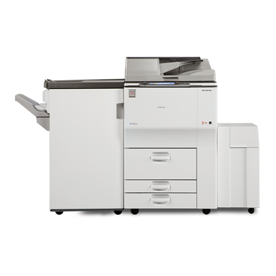
Machine Types Check the type of your machine before reading the manuals. • Type 1: MP 6002/Aficio MP 6002/MP 6002SP/Aficio MP 6002SP • Type 2: MP 7502/Aficio MP 7502/MP 7502SP/Aficio MP 7502SP • Type 3: MP 9002/Aficio MP 9002/MP 9002SP/Aficio MP 9002SP Certain types might not be available in some countries. -
Page 8: Manuals Provided With This Machine
1. Manuals Provided with This Machine This chapter explains manuals for this machine. Manuals for This Machine Read this manual carefully before you use this machine. Refer to the manuals that are relevant to what you want to do with the machine. •... - Page 9 1. Manuals Provided with This Machine Copy/ Document Server Explains Copier and Document Server functions and operations. Also refer to this manual for explanations on how to specify the settings for originals. Explains Facsimile functions and operations. Print Describes how to print using the printer driver. It also describes the functions available for printing. Scan Describes how to scan paper data using this machine and how to send the scanned data to a computer and store the data.
- Page 10 Manuals for This Machine • Driver Installation Guide and HTML manuals are available in English, German, French, Italian, Spanish, Dutch, and Russian. • The following software products are referred to using general names: Product name General name ScanRouter EX Professional the ScanRouter delivery software ScanRouterEX Enterprise *1 The ScanRouter EX Professional and ScanRouterEX Enterprise are no longer available for sale.
-
Page 11: Manuals List
1. Manuals Provided with This Machine Manuals List Printed Manuals HTML Manuals PDF Manuals Manual Name Provided Provided Provided User Guide Read This First Easy Search Getting Started Paper Specifications and Adding Paper Convenient Functions Maintenance and Specifications Troubleshooting Copy/ Document Server Print Scan Connecting the Machine/ System... -
Page 12: On-Screen Operating Instructions
On-screen Operating Instructions On-screen Operating Instructions This chapter describes the on-screen operating instructions of this machine. The on-screen operating instructions are included in the supplied manual CD-ROM. Formats of the Operating Instructions The operating instructions of this machine are provided in the following formats: •... -
Page 13: Installing And Opening The Html Manuals
1. Manuals Provided with This Machine Installing and Opening the HTML Manuals This section describes how to install and open the HTML manuals on your computer. For your convenience, we recommend you install these manuals on your computer. Insert the CD-ROM in the CD-ROM drive of your computer. Select a language, and then click [OK]. - Page 14 On-screen Operating Instructions Insert the CD-ROM in the CD-ROM drive of your computer. Select a language, and then click [OK]. Click [Read PDF manuals]. • To view the PDF manuals, you need to have Adobe Acrobat Reader/Adobe Reader installed on your computer.
- Page 15 1. Manuals Provided with This Machine...
-
Page 16: Safety Information
2. Safety Information This chapter describes the safety precautions. Safety During Operation In this manual, the following important symbols are used: Indicates a potentially hazardous situation which, if instructions are not followed, could result in death or serious injury. Indicates a potentially hazardous situation which, if instructions are not followed, may result in minor or moderate injury or damage to property. -
Page 17: Safety Precautions To Be Followed
2. Safety Information Safety Precautions to Be Followed This section explains safety precautions that should always be followed when using this machine. Environments where the machine can be used This section explains safety precautions about environments where the machine can be used. •... -
Page 18: Handling Power Cords And Power Cord Plugs
Safety Precautions to Be Followed • Do not obstruct the machine's vents. Doing so risks fire caused by overheated internal components. • Machine sound levels exceeding LWAd > 63 dB (A) are not suitable for desk work environments, so place the machine in another room. Handling power cords and power cord plugs This section explains safety precautions about handling power cords and power cord plugs. - Page 19 2. Safety Information • The supplied power cord is for use with this machine only. Do not use it with other appliances. Doing so could result in fire or electric shock. • It is dangerous to handle the power cord plug with wet hands. Doing so could result in electric shock.
-
Page 20: Handling The Main Machine
Safety Precautions to Be Followed • If this machine is not going to be used for several days or longer at a time, disconnect its power cord from the wall outlet. • When disconnecting the power cord from the wall outlet, always pull the plug, not the cord. Pulling the cord can damage the power cord. -
Page 21: Handling The Machine's Interior
2. Safety Information • Do not touch this machine if a lightning strike occurs in the immediate vicinity. Doing so could result in electric shock. • The following explains the warning messages on the plastic bag used in this product's packaging. - Page 22 Safety Precautions to Be Followed • Do not remove any covers or screws other than those explicitly mentioned in this manual. Inside this machine are high voltage components that are an electric shock hazard and laser components that could cause blindness. Contact your sales or service representative if any of the machine's internal components require maintenance, adjustment, or repair.
-
Page 23: Handling The Machine's Supplies
2. Safety Information Handling the machine's supplies This section explains safety precautions about handling the machine's supplies. • Do not incinerate toner (new or used) or toner containers. Doing so risks burns. Toner will ignite on contact with naked flame. •... - Page 24 Safety Precautions to Be Followed • When removing jammed paper or replacing toner, avoid getting toner (new or used) on your clothing. If toner comes into contact with your clothing, wash the stained area with cold water. Hot water will set the toner into the fabric and make removing the stain impossible. •...
-
Page 25: Safety Labels Of This Machine
2. Safety Information Safety Labels of This Machine This section explains the machine’s safety information labels. Positions of WARNING and CAUTION labels This machine has labels for WARNING and CAUTION at the positions shown below. For safety, please follow the instructions and handle the machine as indicated. CJZ101... - Page 26 Safety Labels of This Machine CJZ111 The inside of the machine could be very hot. Do not touch the parts which a label is put on. Otherwise, an injury might occur. CJZ112...
- Page 27 2. Safety Information Keep your hands clear of the finisher tray when removing paper jam. You might trap your fingers if you do not. CJZ113 Do not touch the parts a label indicates. The inside of the machine could be very hot. Caution should be taken when removing misfed paper.
- Page 28 Safety Labels of This Machine CJZ114 Do not touch the parts a label indicates. The inside of the machine could be very hot. Caution should be taken when removing misfed paper. CJZ103...
- Page 29 2. Safety Information CJZ115 Keep your hands clear of the finisher tray when removing paper jam. You might trap your fingers if you do not. Finisher SR4060 or Booklet Finisher SR4070 CJZ104...
- Page 30 Safety Labels of This Machine CJZ008 Keep your hands clear of the booklet finisher tray when pulling out or pushing in the finisher's staple unit, or removing paper jam. You might trap your fingers if you do not. Take care not to touch the booklet finisher tray during operation.
- Page 31 2. Safety Information Multi-Folding Unit CJZ105 BQW058S Do not touch the parts a label indicates. The inside of the Multi-Folding Unit could be very hot. Caution should be taken when removing misfed paper. BQW059S...
-
Page 32: Power Switch Symbols
Safety Labels of This Machine Do not touch the parts a label indicates. The inside of the Multi-Folding Unit could be very hot. Caution should be taken when removing misfed paper. BQW060S Do not touch the parts a label indicates. The inside of the Multi-Folding Unit could be very hot. Caution should be taken when removing misfed paper. - Page 33 2. Safety Information...
-
Page 34: Information For This Machine
3. Information for This Machine This chapter describes laws and regulations related to this machine. Duplication and Printing Prohibited Do not copy or print any item for which reproduction is prohibited by law. Copying or printing the following items is generally prohibited by local law: bank notes, revenue stamps, bonds, stock certificates, bank drafts, checks, passports, driver's licenses. -
Page 35: Laser Safety
3. Information for This Machine Laser Safety CDRH Regulations This equipment complies with requirements of 21 CFR subchapter J for class I laser products. This equipment contains four AlGalnP laser diodes, 15 milliwatts, 657–663 nanometer wavelength for each emitter. The beam divergence angle is 16 degrees (minimum) and 23 degrees (maximum) in the vertical direction, and 7.0 degrees (minimum) and 11.0 degrees (maximum) in the horizontal direction, and laser beams are generated in Continuous Wave (CW) mode. -
Page 36: Notes To Usa Users Of Fcc Requirements
Address: 5 Dedrick Place, West Caldwell, NJ 07006 Telephone number: 973-882-2000 Product Name: Multi Function Peripheral Model Number: • MP 6002/Aficio MP 6002/MP 6002SP/Aficio MP 6002SP • MP 7502/Aficio MP 7502/MP 7502SP/Aficio MP 7502SP • MP 9002/Aficio MP 9002/MP 9002SP/Aficio MP 9002SP Note: This equipment has been tested and found to comply with the limits for a Class B digital device, pursuant to Part 15 of the FCC Rules. -
Page 37: Part 68 Of The Fcc Rules Regarding Facsimile Unit
3. Information for This Machine Caution: Changes or modifications not expressly approved by the party responsible for compliance could void the user's authority to operate the equipment. Part 68 of the FCC Rules regarding Facsimile Unit 1. This equipment complies with Part 68 of the FCC rules and requirements adopted by the ACTA. On the cover of this equipment is a label that contains, among other information, a product identifier in the format US:AAAEQ##TXXXXX. - Page 38 Notes to USA Users of FCC Requirements 10. If your home has specially wired alarm equipment connected to the telephone line, ensure the installation of this equipment does not disable your alarm equipment. If you have questions about what will disable alarm equipment, consult your telephone company or a qualified installer. WHEN PROGRAMMING EMERGENCY NUMBERS AND/OR MAKING TEST CALLS TO EMERGENCY NUMBERS: 1.
-
Page 39: Important Safety Instructions For Facsimile Unit
3. Information for This Machine Important Safety Instructions for Facsimile Unit When using your telephone equipment, basic safety precautions should always be followed to reduce the risk of fire, electric shock and injury to persons, including the following: • Do not use this product near water, for example, near a bath tub, wash bowl, kitchen sink or laundry tub, in a wet basement or near a swimming pool. -
Page 40: Notes To Canadian Users Of Facsimile Unit
Notes to Canadian Users of Facsimile Unit Notes to Canadian Users of Facsimile Unit This product meets the applicable Industry Canada technical specifications. The Ringer Equivalence Number is an indication of the maximum number of devices allowed to be connected to a telephone interface. The termination on an interface may consist of any combination of devices subject only to the requirement that the sum of the RENs of all the devices does not exceed five. -
Page 41: Energy Saving Functions
Energy Saving Functions Energy Saving Functions To reduce its power consumption, this machine has the following functions: Low Power mode • If this machine remains idle for a specified period, it automatically reduces its electrical consumption. • The default period the machine waits before entering Low Power mode is 1 minute. This default time can be changed. - Page 42 3. Information for This Machine • Specifications can vary depending on which options are installed on the machine. • For details about how to change the default interval, see "Timer Settings", Connecting the Machine/ System Settings • Depending on which embedded software application is installed on it, the machine might take longer than indicated to enter Sleep mode.
-
Page 43: Notes To Users In The State Of California (Notes To Users In Usa)
Notes to users in the state of California (Notes to Users in USA) Notes to users in the state of California (Notes to Users in USA) Perchlorate Material - special handling may apply, See www.dtsc.ca.gov/hazardouswaste/ perchlorate... -
Page 44: Notes On Lamp(S) Inside This Machine (Notes To Users In Usa)
3. Information for This Machine Notes on lamp(s) inside this machine (Notes to users in USA) -
Page 45: Appendix
4. Appendix This chapter describes trademarks. Trademarks Adobe, Acrobat, PostScript, PostScript 3, and Reader are either registered trademarks or trademarks of Adobe Systems Incorporated in the United States and/or other countries. Firefox is a registered trademark of the Mozilla Foundation. Macintosh and Safari are trademarks of Apple Inc., registered in the United States and other countries. - Page 46 4. Appendix • The product names of Windows Server 2003 R2 are as follows: ® ® Microsoft Windows Server 2003 R2 Standard Edition ® ® Microsoft Windows Server 2003 R2 Enterprise Edition • The product names of Windows Server 2008 are as follows: ®...
- Page 47 MEMO...
- Page 48 MEMO D133-7212...
- Page 49 User Guide What You Can Do with This Machine Getting Started Copy Print Scan Document Server Web Image Monitor Adding Paper and Toner Troubleshooting Appendix For information not in this manual, refer to the HTML/PDF files on the supplied CD-ROM. Read this manual carefully before you use this machine and keep it handy for future reference.
- Page 51 TABLE OF CONTENTS How to Read the Manuals..........................5 Symbols Used in the Manuals........................5 Model-Specific Information..........................6 Names of Major Features..........................7 1. What You Can Do with This Machine I Want to Save Paper............................9 I Want to Convert Documents to Electronic Formats Easily................10 I Want to Register Destinations........................11 I Want to Operate the Machine More Effectively..................12 You Can Customize the [Home] Screen as You Like..................13...
- Page 52 Turning Off the Main Power........................45 When the Authentication Screen is Displayed....................47 User Code Authentication Using the Control Panel..................47 Logging In Using the Control Panel......................47 Logging Out Using the Control Panel......................48 Placing Originals..............................49 Placing Originals on the Exposure Glass....................49 Placing Originals in the Auto Document Feeder..................49 3.
- Page 53 Printing the Journal Manually..........................88 5. Print Quick Install..............................89 Displaying the Printer Driver Properties......................90 Standard Printing..............................91 When Using the PCL 6 Printer Driver......................91 Locked Print...............................92 Sending a Locked Print File.........................92 Printing a Locked Print File Using the Control Panel..................92 Hold Print................................94 Sending a Hold Print File..........................94 Printing a Hold Print File Using the Control Panel..................94 Stored Print................................96...
- Page 54 8. Web Image Monitor Displaying Top Page.............................119 Viewing Received Fax Documents Using Web Image Monitor..............121 9. Adding Paper and Toner Loading Paper into Tray 1..........................123 Loading Paper into the A3/11 × 17 Tray Unit...................125 Loading Paper into Trays 2 and 3........................126 Loading Tab Stock into Trays 2 and 3.....................127 Loading Paper into the Bypass Tray......................128 Settings to Use the Bypass Tray under the Printer Function..............130...
-
Page 55: How To Read The Manuals
How to Read the Manuals Symbols Used in the Manuals This manual uses the following symbols: Indicates points to pay attention to when using the machine, and explanations of likely causes of paper misfeeds, damage to originals, or loss of data. Be sure to read these explanations. Indicates supplementary explanations of the machine's functions, and instructions on resolving user errors. -
Page 56: Model-Specific Information
Model-Specific Information This section explains how you can identify the region your machine belongs to. There is a label on the rear of the machine, located in the position shown below. The label contains details that identify the region your machine belongs to. Read the label. CJS101 The following information is region-specific. -
Page 57: Names Of Major Features
Names of Major Features In this manual, major features of the machine are referred to as follows: • Auto Document Feeder • Large capacity tray... -
Page 59: What You Can Do With This Machine
1. What You Can Do with This Machine You can search for a description by what you want to do. I Want to Save Paper BRL059S Printing multi-page documents on both sides of sheets (Duplex Copy) See "Duplex Copying", Copy/ Document Server Printing multi-page documents and received faxes on a single sheet (Combine (Copier/Fax)) See "Combined Copying", Copy/ Document Server See "Combine Two Originals", Fax... -
Page 60: I Want To Convert Documents To Electronic Formats Easily
1. What You Can Do with This Machine I Want to Convert Documents to Electronic Formats Easily BQX138S Sending scan files See "Basic Procedure for Sending Scan Files by E-mail", Scan Sending the URL of the folder in which scan files are stored See "Sending the URL by E-mail", Scan Storing scan files in a shared folder See "Basic Procedure When Using Scan to Folder", Scan... -
Page 61: I Want To Register Destinations
I Want to Register Destinations I Want to Register Destinations BRL060S Using the control panel to register destinations in the Address Book See "Registering Entered Destinations to the Address Book", Fax See "Registering a destination in the address book manually", Scan Using Web Image Monitor to register destinations from a computer See "Registering Internet Fax Destination Information Using Web Image Monitor", Fax Downloading destinations registered in the machine to the LAN-Fax driver destination list... -
Page 62: I Want To Operate The Machine More Effectively
1. What You Can Do with This Machine I Want to Operate the Machine More Effectively BQX139S Registering and using frequently-used settings (Program) See "Registering Functions in a Program", Convenient Functions Registering frequently-used settings as initial settings (Program as Defaults (Copier/Document Server/Fax/Scanner)) See "Changing the Default Functions of the Initial Screen", Convenient Functions Registering frequently-used printing settings to the printer driver... -
Page 63: You Can Customize The [Home] Screen As You Like
You Can Customize the [Home] Screen as You Like You Can Customize the [Home] Screen as You Like The icons of each function are displayed on the [Home] screen. CJQ611 • You can add shortcuts to often used programs or Web pages to the [Home] screen. The programs or Web pages can be recalled easily by pressing the shortcut icons. -
Page 64: You Can Make Copies Using Various Functions
1. What You Can Do with This Machine You Can Make Copies Using Various Functions CJQ601 • You can print stamps on copies. Stamps can include background numbers, scanned images, dates, and page numbers. • You can reduce or enlarge the copy image. With the Auto Reduce / Enlarge function, the machine automatically detects the original size, and then selects an appropriate reproduction ratio based on the paper size you select. -
Page 65: You Can Print Data Using Various Functions
You Can Print Data Using Various Functions You Can Print Data Using Various Functions CJQ614 • This machine supports network and local connections. • You can send PDF files directly to the machine for printing, without having to open a PDF application. -
Page 66: You Can Utilize Stored Documents
1. What You Can Do with This Machine You Can Utilize Stored Documents You can store files scanned in copier, facsimile, printer, or scanner mode on the machine's hard disk. With Web Image Monitor, you can use your computer to search for, view, print, delete, and send stored files via the network. -
Page 67: You Can Connect Two Machines For Copying
You Can Connect Two Machines for Copying You Can Connect Two Machines for Copying You can connect two machines together with copy connector. When you set up a copy job on one machine (the main machine), data is transferred to the other (the sub-machine) so that copies can be made on both machines simultaneously (Connect Copy). -
Page 68: You Can Send And Receive Faxes Without Paper
1. What You Can Do with This Machine You Can Send and Receive Faxes without Paper Reception You can store and save received fax documents as electronic formats in the machine's hard disk without printing them. CJQ604 You can use Web Image Monitor to check, print, delete, retrieve, or download documents using your computer (Storing received documents). - Page 69 You Can Send and Receive Faxes without Paper CJQ605 • To send a fax, print from the Windows application you are working with, select LAN-Fax as the printer, and then specify the destination. • You can also check the sent image data. •...
-
Page 70: You Can Send And Receive Faxes Using The Internet
1. What You Can Do with This Machine You Can Send and Receive Faxes Using the Internet xxx@xxx.com xxx@xxx.com xxx.xxx.xxx.xxx xxx.xxx.xxx.xxx xxx@xxx.com xxx@xxx.com xxx.xxx.xxx.xxx xxx.xxx.xxx.xxx CJQ606 E-mail Transmission and Reception This machine converts scanned document images to e-mail format, and transmits and receives this data over the Internet. - Page 71 You Can Send and Receive Faxes Using the Internet • For details about how to transmit and receive documents over the Internet, see "Transmission" and "Reception", Fax...
-
Page 72: You Can Send And Receive Faxes By Using The Machine Without Fax Unit Installed
1. What You Can Do with This Machine You Can Send and Receive Faxes by Using the Machine without Fax Unit Installed You can send and receive faxes through a different machine's fax functions via a network (Remote Fax). CJQ612 •... -
Page 73: You Can Use The Facsimile And The Scanner In A Network Environment
You Can Use the Facsimile and the Scanner in a Network Environment You Can Use the Facsimile and the Scanner in a Network Environment CJQ607 • You can send scan files to a specified destination using e-mail (Sending scan files by e-mail). •... -
Page 74: You Can Prevent Information Leakage (Security Functions)
1. What You Can Do with This Machine You Can Prevent Information Leakage (Security Functions) CJQ608 • You can protect documents from unauthorized access and stop them from being copied without permission. • You can control the use of the machine, as well as prevent machine settings from being changed without authorization. -
Page 75: You Can Monitor And Set The Machine Using A Computer
You Can Monitor and Set the Machine Using a Computer You Can Monitor and Set the Machine Using a Computer Using Web Image Monitor, you can check the machine's status and change the settings. CJQ609 You can check which tray is running out of paper, register information in the Address Book, specify the network settings, configure and change the system settings, manage jobs, print the job history, and configure the authentication settings. -
Page 76: You Can Prevent An Unauthorized Copy
1. What You Can Do with This Machine You Can Prevent an Unauthorized Copy You can print embedded pattern on paper to prevent them from being copied. CJQ613 • Using the printer driver, you can embed a pattern in the printed document. If the document is copied on a machine with the Copy Data Security unit, protected pages are grayed out in the copy, preventing confidential information from being copied. -
Page 77: Getting Started
2. Getting Started This chapter describes how to start using this machine. Guide to Names and Functions of Components Guide to Components • Do not obstruct the ventilation holes by placing objects near them or leaning things against them. If the machine overheats, a fault might occur. - Page 78 2. Getting Started 5. Control panel See p.32 "Guide to the Names and Functions of the Machine's Control Panel". 6. Front cover Open to access the inside of the machine. 7. Paper trays (trays 1–3) Load paper here. Tray 1 is a tandem tray where paper on the left side automatically moves to the right when paper there has run out.
- Page 79 Guide to Names and Functions of Components Rear and left view CJS104 1. Ventilation holes Prevent overheating.
-
Page 80: Guide To Functions Of The Machine's Options
2. Getting Started Guide to Functions of the Machine's Options Guide to Functions of the Machine's External Options CJS105 1. Finisher SR4060 Sorts, stacks, and staples multiple sheets of paper. Consists of the following paper trays: • Finisher upper tray •... - Page 81 Guide to Functions of the Machine's Options 7. A3/11 × 17 tray unit You can load paper sizes up to A3 or 11 × 17 in Tray 1 using this unit. If you install the A3/11 × 17 tray unit on your machine, you cannot use it as a tandem tray. 8.
-
Page 82: Guide To The Names And Functions Of The Machine's Control Panel
2. Getting Started Guide to the Names and Functions of the Machine's Control Panel This illustration shows the control panel of the machine with options fully installed. CJS106 1. [Home] key Press to display the [Home] screen. For details, see p.35 "How to Use the [Home] Screen". 2. - Page 83 Guide to the Names and Functions of the Machine's Control Panel See "Changing the Default Functions of the Initial Screen", Convenient Functions 6. [Interrupt] key Press to make interrupt copies. See "Interrupt Copy", Copy/ Document Server 7. Main power indicator The main power indicator goes on when you turn on the main power switch.
- Page 84 2. Getting Started 19. Data In indicator (facsimile and printer mode) Flashes when the machine is receiving print jobs or LAN-Fax documents from a computer. See Fax Print 20. Communicating indicator, Fax Received indicator, Confidential File indicator • Communicating indicator Lights continuously during data transmission and reception.
-
Page 85: How To Use The [Home] Screen
How to Use the [Home] Screen How to Use the [Home] Screen The icons of each function are displayed on the [Home] screen. You can add shortcuts to frequently used programs or Web pages to the [Home] screen. The icons of added shortcuts appear on the [Home] screen. -
Page 86: Adding Icons To The [Home] Screen
2. Getting Started 7. Shortcut icon You can add shortcuts to programs or Web pages to the [Home] screen. For details about how to register shortcuts, see p.36 "Adding Icons to the [Home] Screen". The program number appears on the bottom of the shortcut icon. - Page 87 How to Use the [Home] Screen Adding icons to the [Home] screen using Web Image Monitor Start Web Image Monitor. For details, see "Using Web Image Monitor", Connecting the Machine/ System Settings Log in to Web Image Monitor as an administrator. For details, see Security Guide Point to [Device Management], and then click [Device Home Management].
- Page 88 2. Getting Started Press [Add Icon]. Press the [Program] tab. Make sure that [Copier Program] is selected. Select the program you want to add.
- Page 89 How to Use the [Home] Screen Specify the position where [Blank] is displayed. Press [OK]. Press the [User Tools/Counter] key. • Press [ ] on the upper-right corner of the screen to check the position on the simple screen.
-
Page 90: Registering Functions In A Program
2. Getting Started Registering Functions in a Program Depending on the functions, the number of programs that can be registered is different. • Copier: 25 programs • Document Server: 25 programs • Facsimile: 100 programs • Scanner: 25 programs The following settings can be registered to programs: Copier: Original type, density, Special Original, paper tray, Store File (except for User Name and Password), Create Margin, Finishing, Cover/Slip Sheet, Edit / Stamp, Dup./Combine/Series,... - Page 91 Registering Functions in a Program Edit the copy settings so all functions you want to store in a program are selected. Press the [Program] key. CJU601 Press [Program]. Press the program number you want to register. Enter the program name. Press [OK].
-
Page 92: Example Of Programs
2. Getting Started • When the paper tray you specified in a program is empty and if there is more than one paper tray with the same size paper in it, the paper tray prioritized under [Paper Tray Priority: Copier], [Paper Tray Priority: Facsimile], or [Paper Tray Priority: Printer] in the [Tray Paper Settings] tab will be selected first. - Page 93 Registering Functions in a Program Program name Program description Effect Stamping Specify [User Stamp] in [Edit / You can stamp the name of your corporate name Stamp]. company on copies of working or copy architectural drawings. Your company name needs to be pre- registered in the machine.
- Page 94 2. Getting Started Program name Program description Effect Dividing file scan Specify [Divide] in [Original Feed You can scan a multiple page Type]. original as one file by splitting it into groups of a specified number of pages. High resolution Specify settings to save scanned Scanned documents maintain much scan...
-
Page 95: Turning On/Off The Power
Turning On/Off the Power Turning On/Off the Power The main power switch is on the left side of the machine. Turning off this switch makes the main power indicator on the right side of the control panel go off. When this is done, machine power is off. When the fax unit is installed, fax files in memory may be lost if you turn this switch off. - Page 96 2. Getting Started • Before unplugging the power cord plug, turn off the main power switch and make sure the main power switch indicator turns off. Not doing so may result in damage to the hard disk or memory, leading to malfunctions. •...
-
Page 97: When The Authentication Screen Is Displayed
When the Authentication Screen is Displayed When the Authentication Screen is Displayed If Basic Authentication, Windows Authentication, LDAP Authentication, or Integration Server Authentication is active, the authentication screen appears on the display. The machine only becomes operable after entering your own Login User Name and Login Password. If User Code Authentication is active, you cannot use the machine until you enter the User Code. -
Page 98: Logging Out Using The Control Panel
2. Getting Started Press [Login]. Enter a Login User Name, and then press [OK]. Enter a Login Password, and then press [OK]. When the user is authenticated, the screen for the function you are using appears. Logging Out Using the Control Panel This section explains the procedure for logging out the machine when Basic Authentication, Windows Authentication, LDAP Authentication, or Integration Server Authentication is set. -
Page 99: Placing Originals
Placing Originals Placing Originals Placing Originals on the Exposure Glass • Do not lift the ADF forcefully. Otherwise, the cover of the ADF might open or be damaged. Lift the ADF. Be sure to lift the ADF by more than 30 degrees. Otherwise, the size of the original might not be detected correctly. - Page 100 2. Getting Started CJW113 1. Sensors Adjust the original guide to the original size. Set the aligned originals squarely face up in the ADF. Do not stack originals beyond the limit mark. The first page should be on the top. CJW114 1.
-
Page 101: Copy
3. Copy This chapter describes frequently used copier functions and operations. For the information not included in this chapter, see Copy/ Document Server on the supplied CD-ROM. Basic Procedure To make copies of originals, place them on the exposure glass or in the ADF. When placing the original on the exposure glass, start with the first page to be copied. -
Page 102: Auto Reduce / Enlarge
3. Copy Auto Reduce / Enlarge The machine automatically detects the original size and then selects an appropriate reproduction ratio based on the paper size you select. CKN008 • If you select a reproduction ratio after pressing [Auto Reduce / Enlarge], [Auto Reduce / Enlarge] is canceled and the image cannot be rotated automatically. - Page 103 Auto Reduce / Enlarge Press [Auto Reduce / Enlarge]. Select the paper size. Place the originals, and then press the [Start] key.
-
Page 104: Duplex Copying
3. Copy Duplex Copying Copies two 1-sided pages or one 2-sided page onto a 2-sided page. During copying, the image is shifted to allow for the binding margin. CKN009 There are two types of Duplex. 1 Sided 2 Sided Copies two 1-sided pages on one 2-sided page. 2 Sided 2 Sided Copies one 2-sided page on one 2-sided page. - Page 105 Duplex Copying Original Original Placing originals Orientation Copy Orientation Top to Top Top to Bottom Press [Dup./Combine/Series]. Make sure that [Duplex] is selected. If [Duplex] is not selected, press [Duplex]. Select [1 Sided 2 Sided] or [2 Sided 2 Sided] according to how you want the document to be output.
-
Page 106: Combined Copying
3. Copy Combined Copying This mode can be used to select a reproduction ratio automatically and copy the originals onto a single sheet of copy paper. The machine selects a reproduction ratio between 25 and 400%. If the orientation of the original is different from that of the copy paper, the machine will automatically rotate the image by 90 degrees to make copies properly. -
Page 107: One-Sided Combine
Combined Copying CKN010 • Originals read from right to left CKN017 One-Sided Combine Combine several pages onto one side of a sheet. CKN014 There are six types of One-Sided Combine. 1 Sided 2 Originals Combine 1 Side Copies two 1-sided originals to one side of a sheet. 1 Sided 4 Originals Combine 1 Side Copies four 1-sided originals to one side of a sheet. -
Page 108: Two-Sided Combine
3. Copy 2 Sided 4 Pages Combine 1 Side Copies two 2-sided originals to one side of a sheet. 2 Sided 8 Pages Combine 1 Side Copies four 2-sided originals to one side of a sheet. Press [Dup./Combine/Series]. Press [Combine]. Select [1 Sided] or [2 Sided] for [Original:]. - Page 109 Combined Copying CKN074 There are six types of Two-Sided Combine. 1 Sided 4 Originals Combine 2 Sides Copies four 1-sided originals to one sheet with two pages per side. 1 Sided 8 Originals Combine 2 Sides Copies eight 1-sided originals to one sheet with four pages per side. 1 Sided 16 Originals Combine 2 Sides Copies 16 1-sided originals to one sheet with eight pages per side.
- Page 110 3. Copy Select [1 Sided] or [2 Sided] for [Original:]. Press [Combine 2 Sides]. Press [Orientation]. Select [Top to Top] or [Top to Bottom] for [Original:] and/or [Copy:], and then press [OK]. Select the number of originals to combine. Press [OK]. Select the paper size.
-
Page 111: Copying Onto Custom Size Paper From The Bypass Tray
Copying onto Custom Size Paper from the Bypass Tray Copying onto Custom Size Paper from the Bypass Tray Paper that has a horizontal length of 139.7–600.0 mm (5.50–23.62 inches) and a vertical length of 100.0–305.0 mm (3.94–12.00 inches) can be fed in from the bypass tray. Note however that the limitation on the horizontal and vertical length range will vary depending on which options are installed. -
Page 112: Finishing
3. Copy Finishing Staple Each copy set can be stapled together. CKN021 • You cannot use the bypass tray with this function. Original orientation and staple position Place all the originals in the ADF in the orientation in which they can be read normally. When placing the original on the exposure glass, keep the same orientation, but place the original facing downwards. - Page 113 Finishing Placing the original on Placing the original in the Staple position the exposure glass Left 2 Top 2 *2 *3 Center *1 The above tables show staple positioning. The orientation of the paper does not indicate orientation of delivery. *2 You cannot staple at this position when copying onto B4 JIS, 8 ×...
-
Page 114: Punch
3. Copy Select one of the staple positions. When you select a staple position, Sort is automatically selected. Press [OK]. Enter the number of copy sets with the number keys. Place the originals, and then press the [Start] key. Punch You can make punch holes in copies. - Page 115 Finishing When the paper that is loaded is the same size and orientation as the original, the relationship between the orientation in which you place the original and the punch hole positions is as follows. You can confirm the punch hole positions that can be selected on the screen that appears when [Finishing] is pressed.
-
Page 116: Fold
3. Copy Press [Finishing]. Press [Finisher]. Select one of the punch hole positions. Press [OK]. Enter the number of copy sets with the number keys. Place the originals, and then press the [Start] key. Fold Copies can be folded in the following ways: Z-fold, Half Fold, Letter Fold-out, Letter Fold-in, Double Parallel Fold, and Gate Fold. - Page 117 Finishing CNP005 To use the Z-fold function, you must set the Z-fold support tray. For details about how to set the Z-fold support tray, see "When the Amount of Output Paper Is Less than the Stack Capacity", Troubleshooting • You cannot use Punch with this function. Original orientation and Z-fold position Place all the originals in the ADF in the orientation in which they can be read normally.
- Page 118 3. Copy Press [Finishing]. Press [Fold]. Select the folding direction, and then press [OK]. Place the originals, and then press the [Start] key. Half Fold Applies a single, central fold to create two equal panels. CNP014...
- Page 119 Finishing Press [Finishing]. Press [Fold]. Press [Half Fold]. Press [Change]. Select [Fold Orientation], [Print Side], and [Multi-sheet Fold]. Press [OK] twice. Place the originals, and then press the [Start] key. Letter Fold-out Applies two folds to create three equal panels (the first panel folding inward, the last panel folding outward).
- Page 120 3. Copy CNP015 To fold multiple sheets with the Letter Fold-out function, you must install the Z-fold support tray for the multi-folding unit. For details about how to install the Z-fold support tray, see "When the Amount of Output Paper Is Less than the Stack Capacity", Troubleshooting Press [Finishing].
- Page 121 Finishing Letter Fold-in Applies two folds to create three equal panels (outer panels folding inward). CNP016 Press [Finishing]. Press [Fold]. Press [Letter Fold-in]. Press [Change]. Select [Fold Orientation], [Open Orientation], [Print Side], and [Multi-sheet Fold]. Press [OK] twice. Place the originals, and then press the [Start] key.
- Page 122 3. Copy Double Parallel Fold Applies two parallel folds to create four panels (center line main fold, double panel fold). CNP019 Press [Finishing]. Press [Fold]. Press [Dble. Parallel Fold]. Press [Change]. Select [Fold Orientation], [Open Orientation], and [Print Side]. Press [OK] twice. Place the originals, and then press the [Start] key.
- Page 123 Finishing Gate Fold Applies three folds to create four equal panels (center line main fold, outer panels folding inward without overlap). CNP020 Press [Finishing]. Press [Fold]. Press [Gate Fold]. Press [Change]. Select [Fold Orientation] and [Print Side]. Press [OK] twice. Place the originals, and then press the [Start] key.
-
Page 124: Storing Data In The Document Server
3. Copy Storing Data in the Document Server The Document Server enables you to store documents being read with the copy feature on the hard disk of this machine. Thus you can print them later applying necessary conditions. You can check the stored documents from the Document Server screen. For details about the Document Server, see p.115 "Storing Data". -
Page 125: Fax
4. Fax This chapter describes frequently used facsimile functions and operations. For the information not included in this chapter, see Fax on the supplied CD-ROM. Basic Procedure for Transmissions (Memory Transmission) This section describes the basic procedure for transmitting documents using Memory Transmission. You can specify the fax, IP-Fax, Internet Fax, e-mail, or folder destinations. - Page 126 4. Fax Make sure [Immed. TX] is not highlighted. Place the original into the ADF. Make the scan settings such as scan size and resolution. Configure the transmission settings such as "TX Mode" as necessary. Specify a destination. You can enter the destination's number or address directly or select from the Address Book by pressing the destination key.
-
Page 127: Registering A Fax Destination
Basic Procedure for Transmissions (Memory Transmission) If you send documents to Internet Fax or e-mail destinations or enable the "E-mail TX Results" function, specify a sender. Press the [Start] key. Registering a Fax Destination Press the [User Tools/Counter] key. Press [Address Book Mangmnt]. Check that [Program / Change] is selected. -
Page 128: Deleting A Fax Destination
4. Fax Enter the fax number using the number keys, and then press [OK]. Specify optional settings such as "SUB Code", "SEP Code", and "International TX Mode". Press [OK]. Press [Exit]. Press the [User Tools/Counter] key. Deleting a Fax Destination •... - Page 129 Basic Procedure for Transmissions (Memory Transmission) Press [Delete All], and then press [OK]. Press [OK]. Press [Exit]. Press the [User Tools/Counter] key.
-
Page 130: Transmitting While Checking Connection To Destination (Immediate Transmission)
4. Fax Transmitting while Checking Connection to Destination (Immediate Transmission) Using Immediate Transmission, you can send documents while checking the connection to the destination. You can specify fax or IP-Fax destinations. If you specify Internet Fax, e-mail, folder destinations, and group or multiple destinations, the transmission mode is automatically switched to Memory Transmission. - Page 131 Transmitting while Checking Connection to Destination (Immediate Transmission) Specify a destination. If you make a mistake, press the [Clear] key, and then enter again. Press the [Start] key.
-
Page 132: Canceling A Transmission
4. Fax Canceling a Transmission This section explains how to cancel a fax transmission. Canceling a Transmission Before the Original Is Scanned Use this procedure to cancel a transmission before pressing the [Start] key. Press the [Reset] key. CJN023 Canceling a Transmission While the Original Is Being Scanned Use this procedure to cancel scanning or transmitting of the original while it is being scanned. -
Page 133: Canceling A Transmission After The Original Is Scanned
Canceling a Transmission Press [Cancel Scanning] or [Cancel TX]. Depending on the transmission mode and function you use, either [Cancel Scanning] or [Cancel TX] is displayed. Canceling a Transmission After the Original Is Scanned Use this procedure to cancel a transmission after the original is scanned. You can cancel transmission of a file while the file is being sent, stored in memory, or if it fails to transmit. -
Page 134: Sending At A Specific Time (Send Later)
4. Fax Sending at a Specific Time (Send Later) Using this function, you can instruct the machine to delay transmission of your fax document until a specified later time. This allows you to take advantage of off-peak telephone charges without having to be by the machine at the time. -
Page 135: Storing A Document
Storing a Document Storing a Document You can store and send a document at the same time. You can also just store a document. The following information can be set for the stored documents as necessary: User Name You can set this function if necessary to know who and what departments stored documents in the machine. -
Page 136: Sending Stored Documents
4. Fax Set the user name, file name, and password as necessary. • User Name Press [User Name], and then select a user name. To specify an unregistered user name, press [Manual Entry], and then enter the name. After specifying a user name, press [OK]. •... - Page 137 Storing a Document Press [Select Stored File]. Select the documents to be sent. When multiple documents are selected, they are sent in the order of selection. • Press [User Name] to place the documents in order by programmed user name. •...
-
Page 138: Printing The Journal Manually
4. Fax Printing the Journal Manually To print the Journal manually, select the printing method: "All", "Print per File No.", or "Print per User". Prints the results of communications in the order made. Print per File No. Prints only the results of communications specified by file number. Print per User Prints the results of communications by individual senders. -
Page 139: Print
5. Print This chapter describes frequently used printer functions and operations. For the information not included in this chapter, see Print on the supplied CD-ROM. Quick Install You can install the printer drivers easily from the CD-ROM provided with this machine. Using Quick Install, the PCL 6 printer driver is installed under network environment, and the Standard TCP/IP port will be set. -
Page 140: Displaying The Printer Driver Properties
5. Print Displaying the Printer Driver Properties This section explains how to open the printer driver properties from [Devices and Printers]. • Manage Printers permission is required to change the printer settings. Log on as an Administrators group member. • You cannot change the machine default settings for individual users. Settings made in the printer properties dialog box are applied to all users. -
Page 141: Standard Printing
Standard Printing Standard Printing • The default setting is duplex printing. If you want to print on only one side, select [Off] for the duplex setting. • If you send a print job via USB 2.0 while the machine is in Low Power mode or Sleep mode, an error message might appear when the print job is complete. -
Page 142: Locked Print
5. Print Locked Print Sending a Locked Print File Click the WordPad menu button in the upper left corner of the window, and then click [Print]. In the "Select Printer" list, select the printer you want to use. Click [Preferences]. In the "Job Type:"... - Page 143 Locked Print Press the [Print Jobs] tab. Press [Locked Print Job]. Select the files you want to print. You can select all the Locked Print files at once by pressing [Select All Jobs] after selecting a file. Press [Print]. Enter the password using the number keys, and then press [OK]. To change the print settings of the document, press [Detailed Settings].
-
Page 144: Hold Print
5. Print Hold Print Sending a Hold Print File Click the WordPad menu button in the upper left corner of the window, and then click [Print]. In the "Select Printer" list, select the printer you want to use. Click [Preferences]. In the "Job Type:"... - Page 145 Hold Print Press the [Print Jobs] tab. Press [Hold Print Job]. Select the files you want to print. You can select all the Hold Print files at once by pressing [Select All Jobs] after selecting a file. Press [Print]. To change the print settings of the document, press [Detailed Settings]. Enter the number of copies using the number keys if necessary, and then press [Print].
-
Page 146: Stored Print
5. Print Stored Print Sending a Stored Print File Click the WordPad menu button in the upper left corner of the window, and then click [Print]. In the "Select Printer" list, select the printer you want to use. Click [Preferences]. In the "Job Type:"... -
Page 147: Printing A Stored Print File Using The Control Panel
Stored Print Printing a Stored Print File Using the Control Panel • The stored documents are not deleted even after the printing has been completed. For the procedure to delete the documents, see "Deleting Stored Print files", Print Press the [Home] key on the top left of the control panel, and press the [Printer] icon on the [Home] screen. -
Page 148: Direct Printing From A Removable Memory Device
Printing Files from an External Memory Device Printing Files from an External Memory Device Printing Files from an External Memory Device Direct Printing from a Removable Memory Device • Using the Media Slot • Printable File Formats • Printing from a Removable Memory Device •... - Page 149 Printing Files from an External Memory Device Using the Media Slot • USB flash memory devices and SD cards are supported for direct printing. However, certain types of USB flash memory devices and SD cards cannot be used. For details, contact your sales or service representative.
-
Page 150: Printing From A Removable Memory Device
Printing Files from an External Memory Device Printing from a Removable Memory Device Insert a removable memory device into the media slot. For details about inserting a removable memory device, see "Inserting/Removing a Memory Storage Device", Getting Started. Press the [Home] key on the top left of the control panel, and press the [Printer] icon on the [Home] screen. - Page 151 Printing Files from an External Memory Device • Depending on the security setting, [Prt. From Dev.] may not appear. For details, see Security Guide • You cannot select multiple files of different formats at the same time. • Files or groups of files larger than 1 GB cannot be printed. •...
-
Page 152: Screen For Direct Printing
Printing Files from an External Memory Device Screen for Direct Printing To display this screen, press the [Home] key on the top left of the control panel, and press the [Printer] icon on the [Home] screen, and then press [Prt. From Dev.]. You can view files either as a list or as thumbnails. - Page 153 Printing Files from an External Memory Device Press to display the print image of the 1st page of the selected document. You can change the scale factor and display position of the print image. [Start Printing] Press to print the selected file. List/Thumbnail Press to switch between list view and thumbnail view.
-
Page 154: Using Pictbridge
Printing Files from an External Memory Device Direct Printing from a Digital Camera (PictBridge) You can connect a PictBridge-compatible digital camera to this machine using a USB cable. This allows you to print photographs taken using the digital camera directly by operating the digital camera. -
Page 155: Exiting Pictbridge
Printing Files from an External Memory Device • Some digital cameras require settings for manual PictBridge operation. For details, see your digital camera's manual. Exiting PictBridge • Do not disconnect the USB cable while data is being sent to the machine. If you do, printing will fail. - Page 156 5. Print...
-
Page 157: Scan
6. Scan This chapter describes frequently used scanner functions and operations. For the information not included in this chapter, see Scan on the supplied CD-ROM. Basic Procedure When Using Scan to Folder • Before performing this procedure, refer to "Preparation for Sending by Scan to Folder", Scan and confirm the details of the destination computer. -
Page 158: Creating A Shared Folder On A Computer Running Windows/Confirming A Computer's Information
6. Scan If necessary, specify the scan settings according to the original to be scanned. Example: Scanning the document in color/duplex mode, and saving as a PDF file. • Press [Scan Settings], and then press [Full Colour: Text / Photo] in the [Original Type] tab. •... - Page 159 Basic Procedure When Using Scan to Folder Confirm the user name. The user name is displayed under [USERNAME]. Step 2: Creating a shared folder on a computer running Microsoft Windows Create a shared destination folder in Windows and enable sharing. In the following procedure, a computer which is running under Windows 7 Ultimate and participating in a domain is used as an example.
-
Page 160: Registering An Smb Folder
6. Scan Step 3: Specifying access privileges for the created shared folder If you want to specify access privileges for the created folder to allow other users or groups to access the folder, configure the folder as follows: Right-click the folder created in step 2, and then click [Properties]. On the [Security] tab, select [Edit...]. - Page 161 Basic Procedure When Using Scan to Folder • [Frequent]: Added to the page that is displayed first. • [AB], [CD], [EF], [GH], [IJK], [LMN], [OPQ], [RST], [UVW], [XYZ], [1] to [10]: Added to the list of items in the selected title. You can select [Frequent] and one more key for each title.
- Page 162 6. Scan Press [Exit]. If the connection test fails, check the settings, and then try again. Press [OK]. Press [Exit]. Press the [User Tools/Counter] key. Locating the SMB folder manually Press [Change] under "Path". Enter the path where the folder is located. For example: if the name of the destination computer is "User", and the folder name is "Share", the path will be \\User\Share.
-
Page 163: Deleting An Smb Registered Folder
Basic Procedure When Using Scan to Folder You can press [Up One Level] to switch between levels. Select the folder you want to register. Press [OK]. Deleting an SMB Registered Folder Press the [User Tools/Counter] key. Press [Address Book Mangmnt]. Check that [Program / Change] is selected. -
Page 164: Entering The Path To The Destination Manually
6. Scan Entering the Path to the Destination Manually Press [Manual Entry]. Press [SMB]. Press [Manual Entry] on the right side of the path field. Enter the path for the folder. In the following example path, the shared folder name is "user" and the computer name is "desk01": \\desk01\user Press [OK]. -
Page 165: Basic Procedure For Sending Scan Files By E-Mail
Basic Procedure for Sending Scan Files by E-mail Basic Procedure for Sending Scan Files by E- mail Press the [Home] key on the top left of the control panel, and press the [Scanner] icon on the [Home] screen. CJS113 Make sure that no previous settings remain. If a previous setting remains, press the [Reset] key. -
Page 166: Registering An E-Mail Destination
6. Scan Example: Scanning the document in color/duplex mode, and saving as a PDF file. • Press [Scan Settings], and then press [Full Colour: Text / Photo] in the [Original Type] tab. • Press [Original Feed Type], and then press [2 Sided Original]. •... -
Page 167: Deleting An E-Mail Destination
Basic Procedure for Sending Scan Files by E-mail You can select [Frequent] and one more key for each title. Press [E-mail]. Press [Change] under "E-mail Address". Enter the e-mail address. Press [OK]. Select [E-mail / Internet Fax Destination] or [Internet Fax Destination Only]. If [E-mail / Internet Fax Destination] is specified, registered e-mail addresses appear in both the internet fax address display and E-mail address display on the fax function screen, and in the address display on the scanner function screen. -
Page 168: Entering An E-Mail Address Manually
6. Scan Press [Address Book Mangmnt]. Check that [Program / Change] is selected. Select the name whose e-mail address you want to delete. Press the name key, or enter the registered number using the number keys. You can search by the registered name, user code, fax number, folder name, e-mail address, or IP-Fax destination. -
Page 169: Basic Procedure For Storing Scan Files
Basic Procedure for Storing Scan Files Basic Procedure for Storing Scan Files • You can specify a password for each stored file. Files that are not password-protected can be accessed by other users on the same local area network using DeskTopBinder. We recommend that you protect stored files from unauthorized access by specifying passwords. -
Page 170: Checking A Stored File Selected From The List
6. Scan Press [User Name], and then select a user name. To specify an unregistered user name, press [Manual Entry], and then enter the name. After specifying a user name, press [OK]. • File Name Press [File Name], enter a file name, and then press [OK]. •... -
Page 171: Specifying The File Type
Specifying the File Type Specifying the File Type This section explains the procedure for specifying the file type of a file you want to send. File types can be specified when sending files by e-mail or Scan to Folder, sending stored files by e-mail or Scan to Folder, and saving files on a removable memory device. -
Page 172: Specifying Scan Settings
6. Scan Specifying Scan Settings Press [Scan Settings]. Specify resolution, scan size, and other settings, as required. Press [OK]. -
Page 173: Basic Procedure For Saving Scan Files On A Removable Memory Device
Storing the Scanned Documents to a USB Flash Memory or SC Card Storing the Scanned Documents to a USB Flash Memory or SD Card This section explains how to save data on external media using the scanner function. • Keep SD cards or USB flash memory devices out of reach of children. If a child accidentally swallows an SD card or USB flash memory device, consult a doctor immediately. - Page 174 Storing the Scanned Documents to a USB Flash Memory or SC Card Insert a removable memory device in the media slot. You can connect only one removable memory device at a time. The media slot cannot be used if both an SD card and a USB flash memory are inserted into it at the same time. Make sure that no previous settings remain.
- Page 175 Storing the Scanned Documents to a USB Flash Memory or SC Card Remove the memory device from the media slot. Remove the media from the media slot only after data has been written completely. Removing the media while data is being written will result in corrupted data. •...
- Page 176 Storing the Scanned Documents to a USB Flash Memory or SC Card 114D...
-
Page 177: Document Server
7. Document Server This chapter describes frequently used Document Server functions and operations. For the information not included in this chapter, see Copy/ Document Server on the supplied CD-ROM. Storing Data This section describes the procedure for storing documents on the Document Server. •... - Page 178 7. Document Server Press the [Home] key on the top left of the control panel, and press the [Document Server] icon on the [Home] screen. CJS113 Press [To Scanning Screen]. Press [User Name]. Specify a user name, and then press [OK]. The user names shown are names that were registered in the Address Book.
-
Page 179: Printing Stored Documents
Printing Stored Documents Printing Stored Documents Prints stored documents on the Document Server. The items you can specify on the printing screen are as follows: • Paper tray • The number of prints • [Finishing] ([Finisher], [Fold]) • [Cover/Slip Sheet] ([Front Cover], [Back Cover], [Designate/Chapter], [Slip Sheet]) •... - Page 180 7. Document Server...
-
Page 181: Web Image Monitor
8. Web Image Monitor This chapter describes frequently used Web Image Monitor functions and operations. For the information not included in this chapter, see Connecting the Machine/ System Settings on the supplied CD-ROM or Web Image Monitor Help. Displaying Top Page This section explains the Top Page and how to display Web Image Monitor. - Page 182 8. Web Image Monitor 3. Refresh/Help (Refresh): Click at the upper right in the work area to update the machine information. Click the Web browser's [Refresh] button to refresh the entire browser screen. (Help): Use Help to view or download Help file contents. 4.
-
Page 183: Viewing Received Fax Documents Using Web Image Monitor
Viewing Received Fax Documents Using Web Image Monitor Viewing Received Fax Documents Using Web Image Monitor Start Web Image Monitor. Click [Fax Received File] on the [Print Job/Stored File] menu in the left pane. If you have programmed a user code for the stored reception file, enter the code, and then press [OK]. - Page 184 8. Web Image Monitor...
-
Page 185: Adding Paper And Toner
9. Adding Paper and Toner This chapter describes how to load paper into the paper tray and recommended paper sizes and types. Loading Paper into Tray 1 • When paper loaded in the right side of tray 1 runs out, paper on the left is automatically shifted to the right. - Page 186 9. Adding Paper and Toner CJW106 • Left half of the tray pulled out CJW107 Carefully push the paper tray fully in. • You can load paper even if tray 1 is in use. It is okay to pull out the left half of the tray while tray 1 is in use.
-
Page 187: Loading Paper Into The A3/11 × 17 Tray Unit
Loading Paper into the A3/11 × 17 Tray Unit Loading Paper into the A3/11 × 17 Tray Unit • (mainly Europe and Asia) A3/11 × 17 tray unit can hold A3 paper only. If you want to print on A4 , B4 JIS , 11 ×... -
Page 188: Loading Paper Into Trays 2 And 3
9. Adding Paper and Toner Loading Paper into Trays 2 and 3 In the following example procedure, paper is loaded into tray 2. • If a paper tray is pushed vigorously when putting it back into place, the position of the tray's side fences may slip out of place. -
Page 189: Loading Tab Stock Into Trays 2 And 3
Loading Paper into Trays 2 and 3 Loading Tab Stock into Trays 2 and 3 • When loading tab stock, always use the tab sheet holder. CJW101 • Load tab stock so that the side with the tab faces the tab sheet holder. •... -
Page 190: Loading Paper Into The Bypass Tray
9. Adding Paper and Toner Loading Paper into the Bypass Tray Use the bypass tray to use OHP transparencies, adhesive labels, translucent paper, and paper that cannot be loaded in the paper trays. • The maximum number of sheets you can load at the same time depends on paper type. Load only as much paper as can be held between the paper guides on the bypass tray. - Page 191 Loading Paper into the Bypass Tray • Certain types of paper might not be detected properly when placed on the bypass tray. If this happens, remove the paper and place it on the bypass tray again. • Pull the extender out when loading A4 , 8 ×...
-
Page 192: Settings To Use The Bypass Tray Under The Printer Function
9. Adding Paper and Toner Settings to Use the Bypass Tray under the Printer Function • If you select [Machine Setting(s)] in [Bypass Tray] under [Tray Setting Priority] in [System] of the Printer Features menu, the settings made using the control panel have priority over the printer driver settings. - Page 193 Loading Paper into the Bypass Tray Press [OK]. Press the [User Tools/Counter] key. • When loading thick paper or OHP transparencies, specify the paper size and the paper type. Setting custom size paper using the control panel Press the [User Tools/Counter] key. CJS039 Press [Tray Paper Settings].
- Page 194 9. Adding Paper and Toner Press the [User Tools/Counter] key. CJS039 Press [Tray Paper Settings]. Press [ Next]. Press [Paper Type: Bypass Tray]. Select the proper items, according to the paper type you want to set. • Press [OHP (Transparency)] on the [Paper Type] area when loading OHP transparencies. •...
-
Page 195: Loading Paper Into The Large Capacity Tray
Loading Paper into the Large Capacity Tray Loading Paper into the Large Capacity Tray • (mainly Europe and Asia) The LCT can hold A4 paper only. If you want to print on 8 × 11 or B5 JIS from the LCT, contact your service representative. - Page 196 9. Adding Paper and Toner CJW110 Load paper by repeating steps 2 and 3. Close the top cover of the LCT.
-
Page 197: Recommended Paper Sizes And Types
Recommended Paper Sizes and Types Recommended Paper Sizes and Types This section describes recommended paper sizes and types. • If you use damp or curled paper, a staple clogging or paper jam may occur. • Do not use paper designed for inkjet printers, as these may stick to the fusing unit and cause a misfeed. - Page 198 9. Adding Paper and Toner Paper type and weight Paper size Paper capacity 52–128 g/m (14–34 lb. Bond) 1,000 sheets Plain Paper–Thick Paper 1 , B4 JIS , 11 × 17 × 14 , 8 × 11 A3 , A4 , B4 JIS , ×...
- Page 199 Recommended Paper Sizes and Types Paper type and weight Paper size Paper capacity 52–169 g/m (14 lb. Bond–90 lb. 550 sheets Index) Plain Paper–Thick Paper 1 Vertical: 139.7–297.0 mm Horizontal: 139.7–432.0 Vertical: 5.50–11.69 inches Horizontal: 5.50–17.00 inches Tab Stock A4 , 8 ×...
- Page 200 9. Adding Paper and Toner Paper type and weight Paper size Paper capacity 52–216 g/m (14 lb. Bond–80 lb. 550 sheets Cover) Plain Paper–Thick Paper 2 Vertical: 139.7–297.0 mm Horizontal: 180.0–432.0 Vertical: 5.50–11.69 inches Horizontal: 7.09–17.00 inches Tab Stock A4 , 8 ×...
- Page 201 Recommended Paper Sizes and Types Paper type and weight Paper size Paper capacity 52–216 g/m (14 lb. Bond–80 lb. • Plain Paper–Middle Cover) Thick: 100 sheets A6 , B4 JIS , B5 JIS Plain Paper–Thick Paper 2 , B6 JIS , •...
- Page 202 9. Adding Paper and Toner Paper type and weight Paper size Paper capacity OHP transparencies • When no finisher is 50 sheets installed × 11 • When a finisher is installed Translucent paper A3 , A4 , B4 JIS , 50 sheets B5 JIS Label paper (adhesive labels)
- Page 203 Recommended Paper Sizes and Types Paper type and weight Paper size Paper capacity 52–216 g/m (14 lb. Bond–80 lb. • Plain Paper–Middle Cover) Thick: 100 sheets , A5 , A6 , B4 Plain Paper–Thick Paper 2 JIS , B5 JIS , B6 JIS , •...
- Page 204 9. Adding Paper and Toner Paper type and weight Paper size Paper capacity OHP transparencies • When no finisher is 50 sheets installed × 11 • When a finisher is installed Translucent paper A3 , A4 , B4 JIS , 50 sheets B5 JIS Label paper (adhesive labels)
- Page 205 Recommended Paper Sizes and Types Paper type and weight Paper size Paper capacity 52–128 g/m (14–34 lb. Bond) 4,000 sheets Plain Paper–Thick Paper 1 B5 JIS , 8 × 11 A4 , B5 JIS *1 To load paper any of the sizes specified above, contact your service representative. Extension unit Paper type and weight Paper size...
- Page 206 9. Adding Paper and Toner Paper type and weight Paper size Paper capacity 64–216 g/m (17 lb. Bond–80 lb. 200 sheets Cover) Plain Paper–Thick Paper 2 11 × 17 , 8 × 11 × 13 , 8 × 13 × 13 , 8 × 10 , ×...
- Page 207 Recommended Paper Sizes and Types • When copying or printing onto letterhead paper, the paper placing orientation is different depending on which function you are using. See "Loading Orientation-Fixed Paper or Two-Sided Paper", Paper Specifications and Adding Paper • When using the sort function or duplex function, the copy/print speed is slower than usual. •...
-
Page 208: Thick Paper
9. Adding Paper and Toner Thick Paper This section gives you various details about and recommendations concerning thick paper. When loading thick paper of 157–169 g/m (42 lb. Bond–90 lb. Index) in trays 1 and 2, 157–216 (42 lb. Bond–80 lb. Cover) in tray 3 or bypass tray, follow the recommendations below to prevent misfeeds and loss of image quality. -
Page 209: Adding Toner
Adding Toner Adding Toner This section explains precautions when adding toner, how to send faxes or scanned documents when the toner has run out, and how to dispose of used toner. • Do not incinerate toner (new or used) or toner containers. Doing so risks burns. Toner will ignite on contact with naked flame. -
Page 210: Sending Faxes Or Scanned Documents When Toner Has Run Out
9. Adding Paper and Toner • When removing jammed paper or replacing toner, avoid getting toner (new or used) on your clothing. If toner comes into contact with your clothing, wash the stained area with cold water. Hot water will set the toner into the fabric and make removing the stain impossible. •... -
Page 211: Disposing Of Used Toner
Adding Toner • If number of communications executed after the toner has run out and not listed in the automatically output Journal exceeds 200, communication is not possible. Make sure the machine is in facsimile or scanner mode. Press [Exit], and then perform transmission operation. The error message disappears. - Page 212 9. Adding Paper and Toner...
-
Page 213: 10. Troubleshooting
10. Troubleshooting This chapter describes basic troubleshooting procedures. Indicators This section describes the indicators displayed when the machine requires the user to remove misfed paper, to add paper, or to perform other procedures. Indicator Status : Paper Misfeed indicator Appears when a paper misfeed occurs. For details about removing jammed paper, see "Removing Jammed Paper", Troubleshooting : Original Misfeed indicator... - Page 214 10. Troubleshooting Indicator Status : Open Cover indicator Appears when one or more covers of the machine are open.
-
Page 215: When An Indicator For The [Check Status] Key Is Lit
When an Indicator for the [Check Status] Key Is Lit When an Indicator for the [Check Status] Key Is Lit If an indicator for the [Check Status] key lights up, press the [Check Status] key to display the [Check Status] screen. Check the status of each function in the [Check Status] screen. [Check Status] screen CNM024 1. - Page 216 10. Troubleshooting The following table explains problems that cause the indicator to light. Problem Causes Solutions Documents and reports do The paper output tray is full. Remove the prints from the tray. not print out. Documents and reports do There is no paper left. Load paper.
-
Page 217: Panel Tone
Panel Tone Panel Tone The following table describes the meaning of the various beep patterns that the machine produces to alert users about left originals and other machine conditions. Beep pattern Meaning Causes Single short beep Panel/screen input A control panel or screen key was accepted. -
Page 218: When You Have Problems Operating The Machine
10. Troubleshooting When You Have Problems Operating the Machine This section describes common problems and messages. If other messages appear, follow the instructions displayed. Problem Causes Solutions The [Facsimile] or [Scanner] Functions other than the Wait a little longer. icon does not appear on the copier function are not yet [Home] screen even though ready. - Page 219 When You Have Problems Operating the Machine Problem Causes Solutions Nothing happens when the The main power switch is Turn on the main power switch. [Check Status] key or the turned off. [Energy Saver] key is pressed. "Please wait." appears. This message appears when Wait for a while.
- Page 220 10. Troubleshooting Problem Causes Solutions "Authentication has failed." The entered login user name For details about the correct login user appears. or login password is not name and login password, see correct. Security Guide "Authentication has failed." The machine cannot perform For details about authentication, see appears.
- Page 221 When You Have Problems Operating the Machine Problem Causes Solutions Misfeeds occur frequently. Paper of undetectable size • Remove misfed paper. For details has been loaded. about removing jammed paper, see "Removing Jammed Paper", Troubleshooting • If you load a paper size that is not selected automatically, you need to specify the paper size with the control panel.
- Page 222 10. Troubleshooting Problem Causes Solutions Cannot print in duplex You have selected a paper Change the setting for "Apply Duplex" mode. tray that is not set for duplex in [System Settings] to enable duplex printing. printing for the paper tray. For details about setting the "Apply Duplex", see "Tray Paper Settings", Connecting the Machine/ System Settings...
- Page 223 When You Have Problems Operating the Machine Problem Causes Solutions "Shutting down... Please The shut down procedure Follow the message that appears and wait. Main power will be has begun because the main wait until the machine has shut down. turned off automatically.
- Page 224 10. Troubleshooting • Using curled paper often causes misfeeds, soiled paper edges, or slipped positions while performing staple or stack printing. When using curled paper, take the stiffness out of the paper with your hands to straighten out the curl, or load the paper up side down. Also, lay paper on a flat surface to prevent paper from curling, and do not lean it against the wall.
-
Page 225: When Messages Are Displayed On The Control Panel
When Messages Are Displayed on the Control Panel When Messages Are Displayed on the Control Panel Messages Displayed When Using the Copy/Document Server Function This section describes the machine's main messages. If other messages appear, follow their instructions. • If you cannot make copies as you want because of the paper type, paper size or paper capacity problems, use recommended paper. - Page 226 10. Troubleshooting Message Causes Solutions "Cannot punch this paper The Punch function cannot For details about paper, see size." be used with paper size "Specifications for Punch Unit (Finisher selected. SR4060, Booklet Finisher SR4070)" or "Specifications for Punch Unit (Finisher SR4080)", Maintenance and Specifications "Cannot staple paper of this...
- Page 227 When Messages Are Displayed on the Control Panel Message Causes Solutions "Magazine or Booklet mode You selected the Make sure originals for the is not available due to mixed "Magazine" or "Booklet" "Magazine" or "Booklet" function are image mode." function for originals scanned using the same function.
- Page 228 10. Troubleshooting Message Causes Solutions "Rotate Sort is not available A size of paper for which Select a proper paper size. For details with this paper size." Rotate Sort is not available is about paper, see "Sort", Copy/ selected. Document Server "Stapling capacity The number of sheets per set Check the stapler capacity.
- Page 229 When Messages Are Displayed on the Control Panel Message Causes Solutions "Cannot print from the sub- The sub-machine's User Press the [User Tools/Counter] key to machine. Check the status of Tools menu is open. close the User Tools menu. the sub-machine." "Cannot print from the sub- The sub-machine has Continue copying using the main...
-
Page 230: Messages Displayed When Using The Facsimile Function
10. Troubleshooting When the memory becomes full while using the copy/document server function Message Causes Solutions "Memory is full. nn originals The scanned originals Press [Print] to copy scanned originals have been scanned. Press exceed the number of pages and cancel the scanning data. Press [Print] to copy scanned that can be stored in [Clear Memory] to cancel the scanning... - Page 231 When Messages Are Displayed on the Control Panel Message Causes Solutions "Cannot detect original The machine failed to detect On the control panel, under [Scan size. Select scan size." the size of the original. Size], specify the scan area in [Scan Settings], and then resend the document.
- Page 232 10. Troubleshooting Message Causes Solutions "Check whether there are Cannot access SIP server. • Check that the correct SIP Server any network problems." IP Address is listed in [SIP Settings] of [Facsimile Features]. [13-18] For details about SIP Settings, see "Initial Settings", Fax •...
- Page 233 When Messages Are Displayed on the Control Panel Message Causes Solutions "Check whether there are The DNS server, SMTP • Check that the following settings any network problems." server, or folder specified for in [System Settings] are listed transfer to was not found, or correctly.
- Page 234 10. Troubleshooting Message Causes Solutions "Check whether there are E-mail transmission was • Check that User Name and any network problems." refused by SMTP Password for the following authentication, POP before settings in [System Settings] are [14-09] SMTP authentication, or login listed correctly.
- Page 235 When Messages Are Displayed on the Control Panel Message Causes Solutions "Check whether there are No POP3/IMAP4 server • Check that the correct Server any network problems." address is registered. Name or Server Address is listed in [POP3 / IMAP4 Settings] of [15-01] [System Settings].
- Page 236 10. Troubleshooting Message Causes Solutions "Check whether there are Cannot find the DNS server • Check that the following settings any network problems." or POP3/IMAP4 server. in [System Settings] are listed correctly. [15-11] • IP address of the DNS Server •...
- Page 237 When Messages Are Displayed on the Control Panel Message Causes Solutions "Check whether there are • An IP address has not • Check that the correct IP address any network problems." been registered for the is specified for the machine in remote machine.
- Page 238 10. Troubleshooting Message Causes Solutions "Exceeded time limit for A network error has occurred • Try the operation again. If the LDAP server search. Check and connection has failed. message is still shown, the the server status." network may be busy. •...
- Page 239 When Messages Are Displayed on the Control Panel Message Causes Solutions "Original(s) is being A function of the machine Before sending a file by fax, cancel the scanned for a different other than the Facsimile job in progress. For example, press function."...
- Page 240 10. Troubleshooting Message Causes Solutions "Some page(s) are near The first page of the The original's blank side might have blank." document is almost blank. been scanned. Be sure to place your originals correctly. For details about determining the cause of blank pages, see "Detecting Blank Pages", Fax "The selected file(s) You tried to delete a...
- Page 241 When Messages Are Displayed on the Control Panel Message Causes Solutions "Connection with the A network error occurred • Check that the remote machine remote machine has failed. while using the remote fax supports the remote fax function. Check the remote machine function.
- Page 242 10. Troubleshooting Message Causes Solutions "Remote fax is not available The remote fax function does When using the remote fax function, because [User Code not support User Code disable User Code Authentication. For Authentication] is active." Authentication. details about user code authentication, see Security Guide "Transfer error has occured.
- Page 243 When Messages Are Displayed on the Control Panel Message Causes Solutions "Transmission cannot be The device certificate (S/ A new device certificate (S/MIME) performed because the MIME) has expired. must be installed. For details about certificate used for the S/ how to install a device certificate (S/ MIME signature is not MIME), see Security Guide...
- Page 244 10. Troubleshooting Message Causes Solutions "E-mail TX Result cannot be The user certificate For details about the user certificate set because the specified (destination certificate) has (destination certificate), see Security destination's certificate is expired. Guide not currently valid." "The program contains a There is no user certificate For details about the user certificate destination(s) that does not...
- Page 245 When Messages Are Displayed on the Control Panel Message Causes Solutions "XXX cannot be recalled There is no device certificate For details about the device certificate because there is a problem (S/MIME), or the certificate (S/MIME), see Security Guide with the device certificate is invalid.
-
Page 246: Messages Displayed When Using The Printer Function
10. Troubleshooting • If "Check whether there are any network problems." appears, the machine is not correctly connected to the network or the settings of the machine are not correct. If you do not need to connect to a network, you can specify the setting so this message is not displayed, and then the [Check Status] key no longer lights. - Page 247 When Messages Are Displayed on the Control Panel Message Status "Offline" The machine is offline. "Please wait." This message might appear for a second or two while the machine is preparing, performing initial adjustments, or adding toner. Wait a while. "Printing..."...
- Page 248 10. Troubleshooting Message Causes Solutions "Cannot connect with the • The Bluetooth interface Turn off the main power switch, and Bluetooth interface. Check unit was installed while then confirm that the Bluetooth the Bluetooth interface." the machine was turned interface unit was installed correctly. And then, turn on the main power switch again.
- Page 249 When Messages Are Displayed on the Control Panel Message Causes Solutions "Hardware Problem: • The Bluetooth interface Turn off the main power switch, and Wireless Card" unit was connected then confirm the Bluetooth interface unit while the machine was is inserted correctly. And then, turn on (A "wireless LAN board"...
- Page 250 10. Troubleshooting Message Causes Solutions "Problem: Printer Font Error" An error has occurred in the Contact your service representative. font settings. "Problems with the wireless The machine has detected a Check that the Bluetooth unit is installed card. Please call service." Bluetooth failure, or it could properly, or contact your service not detect a Bluetooth unit.
- Page 251 When Messages Are Displayed on the Control Panel Messages during Direct print from a removable memory device Message Causes Solutions "Cannot display files from The memory device used For details about the recommended the selected memory cannot be recognized. memory devices for the Direct printing device."...
-
Page 252: Other Messages
10. Troubleshooting Other messages This section describes likely causes of and possible solutions for the error messages that are printed on the error logs or reports. Message Causes Solutions "84: Error" There is no work area • In [Printer Features], under available for image [System], set [Memory Usage] to processing. - Page 253 When Messages Are Displayed on the Control Panel Message Causes Solutions "An error occurred while You tried to store a file in the On the printer driver, select a job type processing an Unauthorized Document Server when the other than [Document Server] in the Copy Prevention job.
- Page 254 10. Troubleshooting Message Causes Solutions "Collate has been Collate was canceled. Turn off the main power switch, and cancelled." then back on again. If the message appears again, contact your service representative. "Command Error" An RPCS command error Check using the following procedure: occurred.
- Page 255 When Messages Are Displayed on the Control Panel Message Causes Solutions "Duplex has been Duplex printing was • Select the proper paper size for cancelled." canceled. the duplex function. For details about paper, see "Specifications for the Main Unit", Maintenance and Specifications •...
- Page 256 10. Troubleshooting Message Causes Solutions "Exceeded max. number of The maximum page Delete some of the files stored in the pages of Document Server. capacity of the Document Document Server or reduce the number Cannot store." Server was exceeded. of pages that you want to send. "Exceeded max.
- Page 257 When Messages Are Displayed on the Control Panel Message Causes Solutions "HDD is full." The hard disk became full Delete unneeded files stored in the while printing a Sample machine. Print, Locked Print, Hold Alternatively, reduce the data size of Print, or Stored Print file.
- Page 258 10. Troubleshooting Message Causes Solutions "Insufficient Memory" A memory allocation error In [Printer Features], under [System], occurred. set [Memory Usage] to [Font Priority]. PCL 5e Select a lower resolution on the printer driver. For details about how to change the resolution setting, see the printer driver Help.
- Page 259 When Messages Are Displayed on the Control Panel Message Causes Solutions "Output tray has been The output tray was Specify the proper output tray. changed." changed because the paper size of the specified output tray is limited. "Print overrun." Images were discarded In [Printer Features], under [System], while printing.
- Page 260 10. Troubleshooting Message Causes Solutions "Sending data failed." The machine received a Check if the computer is working command to stop correctly. transmission from the printer driver. "Staple has been cancelled." Stapling printing was Check the paper orientation, paper canceled. quantity, print orientation, and staple position.
-
Page 261: Messages Displayed When Using The Scanner Function
When Messages Are Displayed on the Control Panel Message Causes Solutions "You do not have a privilege The logged in user does not For details about how to set to use this function. This have the privileges to permissions, see Security Guide operation has been register programs or change cancelled."... - Page 262 10. Troubleshooting Message Causes Solutions "Cannot communicate with WSD (Device) protocol or For details about how to enable or PC. Contact the WSD (Scanner) protocol is disable the WSD protocol, see Security administrator." disabled. Guide "Cannot detect original size. The original placed on the •...
- Page 263 When Messages Are Displayed on the Control Panel Message Causes Solutions "Cannot start scanning The [Take no action] setting Open scanner properties, click the because communication was has been selected on the [Events] tab, and then select [Start this failed." client computer, forcing the program] as the computer's response client computer to remain...
- Page 264 10. Troubleshooting Message Causes Solutions "Captured file exceeded The maximum number of Reduce the number of pages in the max. number of pages per pages per file has been transmitted file, and then resend the file. Cannot send the exceeded. file.
- Page 265 When Messages Are Displayed on the Control Panel Message Causes Solutions "Exceeded max. E-mail size. The file size per page has Change the facsimile features settings Sending E-mail has been reached the maximum e- as follows: cancelled. Check [Max. E- mail size specified in •...
- Page 266 10. Troubleshooting Message Causes Solutions "Exceeded max. number of The maximum enterable Check the maximum number of alphanumeric characters." number of alphanumeric characters which can be entered, and characters has been then enter it again. For details about exceeded. the maximum enterable number of characters, see "Values of Various Set Items for Transmission/Storage / Delivery Function", Scan...
- Page 267 When Messages Are Displayed on the Control Panel Message Causes Solutions "Exceeded max. page The scan could not be Reduce the number of documents to be capacity per file. Press completed because the written to the memory device, and then [Write] to write the scanned maximum number of pages try again.
- Page 268 10. Troubleshooting Message Causes Solutions "Memory is full. Do you Because there is not enough Specify whether to use the data or not. want to store scanned file?" free hard disk space in the machine for storing in the Document Server, only some of the pages could be scanned.
- Page 269 When Messages Are Displayed on the Control Panel Message Causes Solutions "Original(s) is being A function of the machine Cancel the job that is being processed. scanned for a different other than the Scanner For example, press [Exit], and then function."...
- Page 270 10. Troubleshooting Message Causes Solutions "Selected file is currently in You cannot change the Cancel transmission ("Waiting..." status use. Password cannot be password of a file whose cleared) or the DeskTopBinder setting, changed." status is "Waiting..." or that is and then change the password. being edited with DeskTopBinder.
- Page 271 When Messages Are Displayed on the Control Panel Message Causes Solutions "The entered file name The file name contains a Check the file name specified at the contains invalid character(s). character that cannot be time of scanning. The file name Enter the file name again used.
- Page 272 10. Troubleshooting Message Causes Solutions "Updating the destination list A network error has • Check whether the server is has failed. Try again?" occurred. connected. • Antivirus programs and firewalls can prevent client computers from establishing connection with this machine. •...
- Page 273 When Messages Are Displayed on the Control Panel Message Causes Solutions "Exceeded max. data The data being scanned is Reduce the resolution or [Specify Size] capacity." too large for the scale ratio value, and then try to scan the original specified in [Specify Size].
- Page 274 10. Troubleshooting Message Causes Solutions "XXX cannot be YYY The device certificate (PDF A new device certificate (PDF with because the PDF Digital with digital signature) has digital signature) must be installed. For Signature's device certificate expired. details about how to install a device is not currently valid."...
- Page 275 When Messages Are Displayed on the Control Panel Message Causes Solutions "Transmission cannot be The device certificate (S/ A new device certificate (S/MIME) performed because the MIME) has expired. must be installed. For details about certificate used for the S/ how to install a device certificate (S/ MIME signature is not MIME), see Security Guide...
-
Page 276: When Messages Are Displayed On Your Computer Screen
10. Troubleshooting When Messages Are Displayed on Your Computer Screen Messages Displayed When Using the Scanner Function This section describes likely causes of and possible solutions for the main error messages displayed on the client computer when using the TWAIN driver. If a message not described here appears, act according to the message. - Page 277 When Messages Are Displayed on Your Computer Screen Message Causes Solutions "Cannot detect the paper The set original was • Place the original correctly. size of the original. Specify misaligned. • Specify the scan size. the scanning size." • When placing an original directly on the exposure glass, the lifting/ lowering action of the ADF triggers the automatic original...
- Page 278 10. Troubleshooting Message Causes Solutions "Clear Misfeed(s) in ADF." A paper misfeed has • Remove jammed originals, and occurred inside the ADF. then insert them again. For details about jammed paper, see "Removing Jammed Paper", Troubleshooting • When a misfeed occurs, replace the jammed originals.
- Page 279 When Messages Are Displayed on Your Computer Screen Message Causes Solutions "Insufficient memory. Reduce Scanner memory is • Reset the scan size. the scanning area." insufficient. • Lower the resolution. • Set with no compression. For details about the settings, see TWAIN driver Help.
- Page 280 10. Troubleshooting Message Causes Solutions "Scanner is in use for other A function of the machine • Wait for a while, and then function. Please wait." other than the Scanner reconnect. function is being used such • Cancel the job that is being as the Copier function.
- Page 281 When Messages Are Displayed on Your Computer Screen Message Causes Solutions "Scanner is not available. The machine is not • Check whether the machine is Check the scanner connected to the network connected to the network connection status." correctly. correctly. •...
- Page 282 10. Troubleshooting...
-
Page 283: 11. Appendix
11. Appendix This chapter describes the trademarks. Trademarks Adobe, Acrobat, PostScript, PostScript 3, and Reader are either registered trademarks or trademarks of Adobe Systems Incorporated in the United States and/or other countries. ® The Bluetooth word mark and logos are registered trademarks owned by Bluetooth SIG, Inc. and any use of such marks by Ricoh Company, Ltd. - Page 284 11. Appendix ® ® Microsoft Windows Server 2003 R2 Enterprise Edition • The product names of Windows Server 2008 are as follows: ® ® Microsoft Windows Server 2008 Standard ® ® Microsoft Windows Server 2008 Enterprise • The product names of Windows Server 2008 R2 are as follows: ®...
-
Page 285: Index
INDEX 2 Sided Print............. E-mail address........108, 109, 110 E-mail destination....... 108, 109, 110 Energy Saver key..........A3/11 × 17 tray unit........31, 125 Enter key..............Address book 11, 77, 78, 102, 104, 105, 108, 109 Error message. 163, 168, 184, 185, 190, 199, 214 ADF.............. - Page 286 Paper size............ 130, 135 Paper thickness............ Journal..............Paper tray............... Paper type............Paper weight............LAN-Fax............. 9, 18 Paperless Fax............. 9, 18 Large capacity tray........7, 30, 133 Placing originals............ LCT............. 7, 30, 133 Preventing information leakage......Letter Fold-in............Printer..............Letter Fold-out............Printer Bypass Paper Size......
- Page 287 Start key..............Status message............ Stop key..............Stored Print..........15, 96, 97 Storing a document..........Storing data............Storing received documents......... Storing scan files..........Symbols..............Tab stock.............. Thick paper..........131, 146 Toner........... 147, 148, 149 Trademark............Tray 1..............Tray 2..............Tray 3..............Turning off the power..........
- Page 288 MEMO...
- Page 289 MEMO...
- Page 290 MEMO D133...
- Page 291 © 2011...
- Page 292 D133-7202...
-
Page 293: Operating Instructions
Operating Instructions Driver Installation Guide For safe and correct use, be sure to read the Safety Information in "Read This First" before using the machine. - Page 295 TABLE OF CONTENTS 1. Introduction Start Installer................................3 Software and Utilities Included on the CD-ROM.....................5 Printer Drivers..............................5 TWAIN Driver..............................7 LAN-Fax Driver...............................8 Font Manager..............................9 For Mac OS X Users............................10 2. Installing the Printer Driver Confirming the Connection Method.......................11 Network Connection...........................11 Local Connection............................12 Quick Install..............................13 Installing the Printer Driver for a Network Connection..................14 Installing the Printer Driver for the Selected Port..................14...
- Page 296 Editing the Configuration File........................44 Installing the LAN-FAX driver in "Add Printer"...................45 Setting LAN-Fax Driver Properties........................47 Setting Print Properties..........................47 Configuring Option Settings for the Facsimile...................48 5. Troubleshooting Messages Displayed When Installing the Printer Driver................49 If USB Connection Fails...........................51 6. Installing the Printer Driver Under Mac OS X Installing the PPD Files............................53 Registering the Printer............................54 USB Connection............................54...
-
Page 297: Introduction
1. Introduction This chapter explains the software included on the supplied CD-ROM. Start Installer To connect this machine to a client computer and use its printer, scanner, and fax functions, the software included on the provided CD-ROM must be installed on the client computer. The installer starts automatically when you insert the provided CD-ROM into the CD-ROM drive of a client computer running under Windows or Windows Server. - Page 298 1. Introduction Select Language Change the interface language. Browse This CD-ROM Browse the contents of this CD-ROM. Exit Quit Installer. • Manage Printers permission is required to install the driver. Log on as an Administrators group member. • Auto Run might not work automatically with certain OS settings. If this is the case, double-click "SETUP.EXE", located on the CD-ROM root directory, or click [Run SETUP.EXE] in the [AutoPlay] dialog box.
-
Page 299: Software And Utilities Included On The Cd-Rom
Software and Utilities Included on the CD-ROM Software and Utilities Included on the CD-ROM This section explains the software and utilities CD-ROM provided with this machine. • For the latest information on the corresponding operating system, see "Readme.txt" file in the DRIVERS folder. - Page 300 1. Introduction *7 Mac OS X 10.2 or later (native mode). Any versions higher than Mac OS X 10.6 are not supported. PCL printer drivers Two kinds of PCL printer driver (PCL 5e and PCL 6) are included. These drivers allow your computer to communicate with this machine via a printer language.
-
Page 301: Twain Driver
Software and Utilities Included on the CD-ROM Printer Language Supported languages PCL 5e PCL 6 PostScript 3 PPD (Mac OS X) Hungarian Czech Polish Portuguese Russian Catalan Turkish Brazilian Portuguese Greek : Supported : Supported, but the printer language is displayed in English *1 The PCL 5e printer driver does not support Brazilian Portuguese and Greek. -
Page 302: Lan-Fax Driver
1. Introduction Windows XP/Vista/7 Windows Server 2003/2003 R2/2008/2008 R2 *1 Operates in 32-bit compatibility mode on 64-bit operating systems • Display resolution 800 × 600 pixels, 256 colors or higher Supported languages The TWAIN driver uses the same interface language as the one specified by your operating system. -
Page 303: Font Manager
Software and Utilities Included on the CD-ROM Font Manager For installing new screen fonts, or organizing and managing fonts already in the system. For details about Font Manager, see the manual on the CD-ROM. File path The software is included in the following folder on the CD-ROM: \FONTMAN\DISK1 •... -
Page 304: For Mac Os X Users
1. Introduction For Mac OS X Users If you are using Mac OS X, the following limitations apply to each function: • When using the scanner function, the TWAIN driver cannot be used. • When using the fax function, the LAN-Fax driver cannot be used. •... -
Page 305: Installing The Printer Driver
2. Installing the Printer Driver This chapter explains how to install and configure the printer drivers for use on the Windows operating system. Confirming the Connection Method This machine supports network and local connection. Before installing the printer driver, check how the machine is connected. Follow the driver installation procedure that is appropriate to the connection method. -
Page 306: Local Connection
2. Installing the Printer Driver • For details about how to install the printer driver for each type of port, see p.14 "Installing the Printer Driver for the Selected Port". Using as a network printer This machine can be used as a remote printer using the Windows or NetWare print server function. Client OS Using Server •... -
Page 307: Quick Install
Quick Install Quick Install You can install the printer drivers easily from the CD-ROM provided with this machine. Using Quick Install, the PCL 6 printer driver is installed under network environment, and the Standard TCP/IP port will be set. When the machine is connected to a client computer via parallel connection, the printer port is set to [LPT1]. -
Page 308: Installing The Printer Driver For A Network Connection
2. Installing the Printer Driver Installing the Printer Driver for a Network Connection This section describes the installation procedure of the printer drivers for network connection. • Manage Printers permission is required to install the driver. Log on as an Administrators group member. - Page 309 Installing the Printer Driver for a Network Connection Using the Standard TCP/IP port Quit all applications. (Do not close this manual.) Insert the provided CD-ROM into the computer's CD-ROM drive. If the [AutoPlay] dialog box appears, click [Run AUTORUN.EXE]. Select an interface language, and then click [OK]. For details about the languages supported in the printer drivers, see p.6 "Supported languages".
- Page 310 2. Installing the Printer Driver • Installation of the certificate is especially necessary for users who want to print via IPP-SSL from Windows Vista/7 or Windows Server 2008/2008 R2. For details, consult your administrator. • If a certificate authority issues a certificate that must be authenticated by an intermediate certificate authority, and the certificate is installed on this machine, an intermediate certificate must be installed on the client computer.
- Page 311 Installing the Printer Driver for a Network Connection Select the manufacturer and model name of the machine you want to use, and then click [Next]. The installation starts. Follow the instructions that appear. Modify settings such as printer name and default printer configuration, as necessary.
- Page 312 2. Installing the Printer Driver Using the WSD port • The WSD port can be used under Windows Vista/7, or Windows Server 2008/2008 R2. • You can connect to the printer only if both the printer and computer are on the same network segment, or "Network discovery"...
- Page 313 Installing the Printer Driver for a Network Connection • To stop the installation, click [Cancel] before the installation is complete. When re-installing the WSD Port, right-click the printer's icon in the [Network] window, and then click [Uninstall]. Windows 7, Windows Server 2008 R2 Quit all applications.
- Page 314 2. Installing the Printer Driver Click [Finish]. If installation is successful, the icon of the printer connected to the WSD port will appear in the window for configuring printers. • To stop installation of the selected driver, click [Cancel] before the installation is complete. When re-installing the WSD Port, right-click the machine's icon in the [Network] window, and then click [Uninstall].
- Page 315 Installing the Printer Driver for a Network Connection In the [Printer URL] box, enter "http://machine's IP address/printer" as the machine's address. If the server authentication is issued, enter "https://machine's IP address/printer" to enable SSL (a protocol for encrypted communication). Example IP address: 192.168.15.16 http://192.168.15.16/printer https://192.168.15.16/printer You can enter "http://machine's IP address/ipp"...
-
Page 316: Using As A Network Printer
2. Installing the Printer Driver Click the [Ports] tab, and then click [Configure Port]. The [Port Configuration:] window appears. Windows 7, Windows Server 2008 R2: On the [Start] menu, click [Devices and Printers]. Right-click the icon of the machine you want to use, and then click [Printer Properties]. Click the [Ports] tab, and then click [Configure Port]. - Page 317 Installing the Printer Driver for a Network Connection The software license agreement appears in the [License Agreement] dialog box. After reading the agreement, click [I accept the agreement.], and then click [Next]. If installing the PostScript 3 printer driver, proceed to step 7. Select a printer driver you want to use, and then click [Next].
- Page 318 2. Installing the Printer Driver Select a printer driver you want to use, and then click [Next]. Select the check box of the machine model you want to use. Double-click the machine name to display the printer settings. Click [Port :], and then click [Add] in the [Change settings for 'Port'] box. Click [Network Printer], and then click [OK].
- Page 319 Installing the Printer Driver for a Network Connection • The protocol is set to inactive as default. Enable the protocol on the control panel, using Web Image Monitor, SmartDeviceMonitor or telnet. Notes when using NetWare Form Feed Do not use NetWare to configure form feed. Form feed is controlled by the printer driver on Windows.
- Page 320 2. Installing the Printer Driver 5. Click [OK]. Printing after Resetting the Printer Printer to print server connection requires 30 - 40 seconds to resume after the printer is reset. During this period, jobs may be accepted (depending on NetWare specifications) but not printed. To print after resetting the printer as the remote printer, check on the print server that the remote printer is disconnected, or wait for two minutes before trying to print.
-
Page 321: Installing The Printer Driver For A Local Connection
Installing the Printer Driver for a Local Connection Installing the Printer Driver for a Local Connection This section describes the installation procedure of the printer drivers for USB, parallel, or Bluetooth connection. • Manage Printers permission is required to install the driver. Log on as an Administrators group member. - Page 322 2. Installing the Printer Driver Connect the machine and computer using the USB cable. Connect the USB cable firmly. Turn on the power of the machine. Found New Hardware Wizard starts, and USB Printing Support is installed automatically. Select [No, not this time], and then click [Next]. Click [Install from a list or specific location [Advanced]], and then click [Next].
- Page 323 Installing the Printer Driver for a Local Connection Check that the power of the machine is off. Connect the machine and computer using a USB cable. Connect the USB cable firmly. Turn on the power of the machine. Found New Hardware Wizard starts, and USB Printing Support is installed automatically. In the [Found New Hardware] window, click [Locate and install driver software (recommended)].
- Page 324 2. Installing the Printer Driver Connect the machine and computer using a USB cable. Connect the USB cable firmly. Turn on the power of the machine. Found New Hardware Wizard starts, and USB Printing Support is installed automatically. Click [Devices and Printers] from the [Start] menu. Double-Click the icon of machine you want to use in the [Unspecified] category.
-
Page 325: Parallel Connection
Installing the Printer Driver for a Local Connection Parallel Connection To use a printer connected using a parallel interface, click [LPT1] when installing the printer driver. Quit all applications. (Do not close this manual.) Insert the provided CD-ROM into the computer's CD-ROM drive. If the [AutoPlay] dialog box appears, click [Run AUTORUN.EXE]. - Page 326 2. Installing the Printer Driver Restrictions on SPP, HCRP • A maximum of two Bluetooth adaptor or Bluetooth-equipped computers can be connected at the same time using the Bluetooth interface: one by SPP, one by HCRP. • When connecting more than one Bluetooth adaptor or Bluetooth-equipped computer at the same time, the first device that establishes connection is selected.
- Page 327 Installing the Printer Driver for a Local Connection Click [Bluetooth Printer], and then click [Next]. The computer begins searching for available Bluetooth printers. If a new printer is discovered, the [Found New Hardware Wizard] window appears. To ignore a discovered device and continue searching, click [Cancel]. The computer resumes searching for other available Bluetooth printers.
- Page 328 2. Installing the Printer Driver In the [Found New Hardware] window, select the printer driver you want to use, and then click [Next]. The installation starts. If the [Windows Security] window appears, click [Install this driver software anyway]. Click [Close]. If you want to change the printer name, enter the new name in the [Printer Name Settings] window.
-
Page 329: Configuring Option Settings For The Printer
Configuring Option Settings for the Printer Configuring Option Settings for the Printer When bidirectional communication works correctly, your computer obtains information about option, paper size and paper feed direction settings from the machine automatically. Bidirectional communication also allows you to monitor machine status. When bidirectional communication is disabled, you have to set up option, paper size and paper feed direction settings on your computer manually. -
Page 330: If Bidirectional Communication Is Disabled
2. Installing the Printer Driver If Bidirectional Communication is Disabled This section describes how to set up option, paper size and paper feed direction settings on your computer manually. • Manage Printers permission is required to change the printer properties. Log on as an Administrators group member. -
Page 331: Installing Font Manager
Installing Font Manager Installing Font Manager • Manage Printers permission is required to install Font Manager. Log on as an Administrators group member. • The operating systems compatible with Font Manager are Windows XP/Vista. Quit all applications. (Do not close this manual.) Insert the provided CD-ROM into the computer's CD-ROM drive. -
Page 332: Using Adobe Pagemaker Version 6.0, 6.5, Or 7.0
2. Installing the Printer Driver Using Adobe PageMaker Version 6.0, 6.5, or ® Under Windows XP with Adobe PageMaker , you need to copy PPD files to the PageMaker folder. PPD files have the .ppd extension in the folder "X86\DRIVERS\PS\PM6\ (Language)" on the CD-ROM. The third folder "(Language)"... -
Page 333: Installing The Scanner Driver
3. Installing the Scanner Driver This chapter explains how to install the TWAIN driver on a client computer. Installing the TWAIN Driver To use the network TWAIN scanner, you must install the TWAIN driver on a client computer. Quit all applications. (Do not close this manual.) Insert the provided CD-ROM into the computer's CD-ROM drive. - Page 334 3. Installing the Scanner Driver...
-
Page 335: Installing The Facsimile Driver
4. Installing the Facsimile Driver This chapter explains how to install and configure the LAN-Fax driver on a client computer. Installing the LAN-Fax Driver Address Book and LAN-Fax Cover Sheet Editor are installed with the LAN-Fax Driver. Address Book helps you edit LAN-Fax transmission destinations. LAN-Fax Cover Sheet Editor helps you edit LAN-Fax cover sheets. -
Page 336: Specifying The Port When Installing The Lan-Fax Driver
4. Installing the Facsimile Driver Click [LAN-Fax Driver]. The software license agreement appears in the [License Agreement] dialog box. After reading the agreement, click [I accept the agreement.], and then click [Next]. Click [Next]. Double-click [Printer Name : <LAN-Fax M(number)>]. Click [Port:]. - Page 337 Installing the LAN-Fax Driver Procedure/description in the Procedure/description in the Items to be replaced printer driver LAN-Fax driver • Select the check box of the machine model you want to use. The procedures in the [Install Double-click [Printer Name : Printer Driver] dialog box <LAN-Fax M(number)>].
-
Page 338: Enabling The Function To Prevent Transmission To The Wrong Destination
4. Installing the Facsimile Driver Enabling the Function to Prevent Transmission to the Wrong Destination To enable the function to prevent transmission to the wrong destination, edit the configuration file before you install the driver. This section explains how to edit the configuration file and install the LAN-Fax driver using the edited configuration file. -
Page 339: Installing The Lan-Fax Driver In "Add Printer
Enabling the Function to Prevent Transmission to the Wrong Destination Save the configuration file that has been edited. Installing the LAN-FAX driver in "Add Printer" Install the LAN-FAX driver after the configuration file has been edited. Open the printer window. •... - Page 340 4. Installing the Facsimile Driver Click [Finish]. When you are prompted to restart your computer, restart it by following the instructions that appear.
-
Page 341: Setting Lan-Fax Driver Properties
Setting LAN-Fax Driver Properties Setting LAN-Fax Driver Properties • Manage Printers permission is required to set the properties for the LAN-Fax driver. Log on as an Administrators group member. • The method for selecting the LAN-Fax driver will vary according to your operating system. For details, see Windows Help. -
Page 342: Configuring Option Settings For The Facsimile
4. Installing the Facsimile Driver Configuring Option Settings for the Facsimile Open the printer windows. • Windows XP, Windows Server 2003/2003 R2: On the [Start] menu, select [Printers and Faxes]. • Windows Vista, Windows Server 2008: On the [Start] menu, select [Control Panel], and then click [Printers] in [Hardware and Sound] category. -
Page 343: Troubleshooting
5. Troubleshooting This chapter provides solutions for driver installation and USB connection problems. Messages Displayed When Installing the Printer Driver This section describes what to do if a message appears when installing the printer driver. Message number 58 or 34 indicates that the printer driver cannot be installed using Auto Run. Install the printer driver using Add Printer Wizard. - Page 344 5. Troubleshooting • Available ports vary according to your Windows operating system or the type of interface. For details, see p.11 "Confirming the Connection Method".
-
Page 345: If Usb Connection Fails
If USB Connection Fails If USB Connection Fails This section describes how to troubleshoot a problem related to USB connections. Problem Causes Solutions The machine is not The USB cable is not Disconnect the USB cable, and then automatically recognized. connected properly. - Page 346 5. Troubleshooting...
-
Page 347: Installing The Printer Driver Under Mac Os
6. Installing the Printer Driver Under Mac OS X This chapter explains how to install and configure the printer drivers for use on the Mac OS X operating system. Installing the PPD Files To print using the printer specific features under Mac OS X, install the PPD files. •... -
Page 348: Registering The Printer
6. Installing the Printer Driver Under Mac OS X Registering the Printer To use the machine, the printer must be registered in the printer list. Make sure the machine and computer are connected and turned on, and perform the following procedure. -
Page 349: Network Connection
Registering the Printer Click [Choose]. Click [Add]. If the option settings need to be configured, see p.57 "Configuring Option Settings for the Printer Under Mac OS X". Quit Print Center or Printer Setup Utility. Mac OS X 10.4 - 10.6 Start System Preferences. - Page 350 6. Installing the Printer Driver Under Mac OS X Select the machine you are using from the [Printer Model:] pop-up menu. If the machine you are using is not selected in [Printer Model:], select its manufacturer or [Other...] in the pop-up menu, and then select the PPD file of the machine. For the location of the PPD files, see p.53 "Installing the PPD Files".
-
Page 351: Configuring Option Settings For The Printer Under Mac Os X
Configuring Option Settings for the Printer Under Mac OS X Configuring Option Settings for the Printer Under Mac OS X This section explains how to configure the printer driver. Mac OS X 10.2 - 10.3 Start Print Center or Printer Setup Utility in Applications\Utilities. Click [Set Up Printers...]. - Page 352 6. Installing the Printer Driver Under Mac OS X...
-
Page 353: Appendix
7. Appendix Updating or Deleting the Driver • Administrator permission is required to update or delete the driver in use. Log on as an Administrators group member. • If the [User Account Control] dialog box appears, click [Yes] or [Continue]. •... -
Page 354: Deleting The Driver
7. Appendix Click [OK]. Select the machine model, and then click [Next]. The driver update starts. Click [Finish]. Click [OK] to close the printer properties window. Restart the computer. TWAIN driver You can download the most recent version of the TWAIN driver from the manufacturer's Web site. Delete the old version of the TWAIN driver first, and then install the new TWAIN driver. - Page 355 Updating or Deleting the Driver Click [Delete]. Click [OK]. Click [Close] to close the print server properties window. Windows 7, Windows Server 2008 R2 On the [Start] menu, click [Devices and Printers]. Right-click the icon of the machine you want to delete, and then click [Remove Device]. Click [Yes].
- Page 356 7. Appendix Quit uninstaller.
-
Page 357: Trademarks
Trademarks Trademarks Adobe, PageMaker, and PostScript are either registered trademarks or trademarks of Adobe Systems Incorporated in the United States and/or countries. Macintosh, and Mac OS are registered trademarks of Apple Inc, registered in the U.S. and other countries. IPS is a trademark or registered trademark of Zoran Corporation and/or its subsidiaries in the United States or other countries. - Page 358 7. Appendix ® ® Microsoft Windows 7 Ultimate ® ® Microsoft Windows 7 Enterprise • The product names of Windows Server 2003 are as follows: ® ® Microsoft Windows Server 2003 Standard Edition ® ® Microsoft Windows Server 2003 Enterprise Edition •...
-
Page 359: Index
INDEX Network printer..........12, 22 Bidirectional communication........ BIP................Option settings.......... 35, 48, 57 Bluetooth..............Bluetooth printer............ PageMaker............Parallel connection......... 13, 31 CD-ROM..............PCL............5, 13, 14, 22 Confirming the connection method...... PostScript 3..........5, 14, 22 Connection fails............. PPD................Prevent Transmission to the Wrong Destination. . Printer driver.......... - Page 360 MEMO...
- Page 361 MEMO...
- Page 362 MEMO D129-7861...
- Page 364 D129-7861 © 2011...
- Page 365 Operating Instructions IPDS Supplement For safe and correct use, be sure to read the Safety Information in "Read This First" before using the machine.
- Page 367 TABLE OF CONTENTS Manuals for the IPDS card..........................2 Notice..................................3 Important.................................3 How to Read This Manual..........................4 Symbols................................4 1. Getting Started About IPDS................................5 2. Using Web Image Monitor List of the Setting Items............................7 Configuration..............................7 3. Accessing User Tools User Tools Settings..............................9 List/Test Print..............................9 Maintenance..............................9 IPDS Menu..............................9 4.
-
Page 368: Manuals For The Ipds Card
Manuals for the IPDS card Refer to the manuals that are relevant to what you want to do with the IPDS card. ® ® ® • Adobe Acrobat Reader /Adobe Reader must be installed in order to view the manuals as PDF files. -
Page 369: Notice
Notice Important Contents of this manual are subject to change without prior notice. In no event will the company be liable for direct, indirect, special, incidental, or consequential damages as a result of handling or operating the machine. -
Page 370: How To Read This Manual
How to Read This Manual Symbols This manual uses the following symbols: Indicates points to pay attention to when using the machine, and explanations of likely causes of paper misfeeds, damage to originals, or loss of data. Be sure to read these explanations. Indicates supplementary explanations of the machine's functions, and instructions on resolving user errors. -
Page 371: Getting Started
1. Getting Started About IPDS IPDS (Intelligent Printer Data Stream) is a page printing format for IBM mainframe and client computers. This machine can perform IPDS printing if the IPDS card is installed. - Page 372 1. Getting Started...
-
Page 373: Using Web Image Monitor
2. Using Web Image Monitor List of the Setting Items If you install the IPDS card to the machine, following Web Image Monitor items can be viewed or modified depending on the selected mode on the Web browser. Select one of the following modes to log on Web Image Monitor: •... - Page 374 2. Using Web Image Monitor • "IPDS" and "IPDS Port Number" will be displayed. Security Menu User mode Administrator mode Network Security None Read/Modify • "IPDS" will be displayed.
-
Page 375: Accessing User Tools
3. Accessing User Tools User Tools Settings When the IPDS card is installed, IPDS print settings become available and will appear on the control panel. List/Test Print IPDS Font List Prints a list of IPDS-supported fonts. • The layout of the IPDS Font List produced by the test print is fixed to A4 or 8 11 (letter) size. - Page 376 3. Accessing User Tools For each paper tray, select the form you want to allocate to it. Emulation Mode Specifies the emulation mode. Default: [Native] • Native • 4028 Print Mode Specifies the print mode. Default: [Enhanced] • Standard • Enhanced Default Code Page Specifies the default code page.
- Page 377 User Tools Settings • 424 : Hebrew • 500 : Belgium, Switzerland/International • 870 : Latin 2 Multilingual • 871 : Icelandic • 875 : Greek • 880 : Cyrillic • 892 : OCR - A • 893 : OCR - B •...
- Page 378 3. Accessing User Tools • 46 : Courier Bold 10 • 85 : Courier 12 • 86 : Prestige Elite • 92 : Courier Italic 12 • 111 : Prestige Elite Bold • 112 : Prestige Elite Italic • 159 : Boldface •...
- Page 379 User Tools Settings • 2309 : Times New Roman Bold • 2310 : Times New Roman Italic Medium • 2311 : Times New Roman Italic Bold • 5687 : Times Roman • 5707 : Times Roman Bold • 5815 : Times Roman Italic •...
- Page 380 3. Accessing User Tools Font Substitution Turns font substitution on or off. Default: [Off] • On If a job requests a font that is not loaded on the printer, the printer uses a substitute font. • Off If a job requests a font that is not loaded on the printer, the printer generates an IPDS NACK (Negative Acknowledgement) message and the host holds the job.
- Page 381 User Tools Settings Default: [Auto] • Auto Reports to the host that the printer supports raster fonts of any dpi value and IM1 images. "Resident" or "Captured" raster fonts of other resolutions are not activated unless a matching "Font Resolution" and "Metric Technology Triplet" is provided with the activation request. •...
- Page 382 3. Accessing User Tools Bar Code Specifies the barcode level protocol. Default: [Auto] • Auto Applies the value specified by the [Emulation Mode] item ([Native] or [4028]). • 4028 Applies 4028 IPDS Emulation. • Native Applies Native IPDS Emulation. Box Draw Specifies the Box Draw processing.
- Page 383 User Tools Settings The printer accepts all text color specification controls, but performs only limited color simulation using black. • This menu item is available only if [Color Simulation] mode is set to [Fidelity]. Suppress Staple Count Nacks Selects whether or not to notify the user when stapling errors occur. Default: [Off] •...
- Page 384 3. Accessing User Tools • IPDS Tray • LCT Default: [Auto] • Auto • IPDS Tray • Bypass Tray Default: [Auto] • Auto • IPDS Tray • If [IPDS Tray] is selected, enter the tray parameter replacement value for each paper tray, using up to 254 digits.
- Page 385 User Tools Settings • [Tray Form] allocates the form specified using Web Image Monitor's [IPDS Form List] to the installed tray. For details about IPDS Form List, see the Web Image Monitor Help. • Tray commands of [Tray Form] differ depending on the machine you want to use. For details about selectable tray commands, see "Load Copy Control", IPDS Technical Reference 2.
- Page 386 3. Accessing User Tools...
-
Page 387: Appendix
4. Appendix Precautions Limitations PCL fonts are not accessible via AFP/IPDS, nor can PCL access AFP/IPDS fonts. ® PostScript fonts are not accessible via AFP/IPDS, nor can PostScript access AFP/IPDS fonts. The mainframe or host computer will not be notified of errors that happen before this machine establishes connection with them. -
Page 388: Trademarks
4. Appendix Trademarks Adobe, Acrobat, PostScript, and Reader are either registered trademarks or trademarks of Adobe Systems Incorporated in the United States and/or other countries. AFP/ADVANCED FUNCTION PRINTING, IPDS and Intelligent Printer Data Stream are trademarks of Ricoh Co., Ltd. ®... -
Page 389: Index
INDEX About AFP/IPDS Fonts.......... Offset................ About IPDS............... Precautions............. Bar Code..............Print Mode..............Box Draw..............Printer................ Caching..............Reset IPDS Fonts............Characters Per Inch..........Resolution..............Color Simulation............Configuration............Security..............Corner Staple Angle..........Suppress Punch Nacks..........Suppress Staple Count Nacks........ Default Code Page..........Symbols.............. - Page 390 MEMO D143-7055...
- Page 392 D143-7055 © 2012...
- Page 393 IPDS Technical Reference 1...
- Page 395 TABLE OF CONTENTS Manuals for the IPDS card..........................4 Notice..................................5 Important.................................5 How to Read This Manual..........................6 Symbols................................6 About This Book..............................7 Audience.................................7 Terminology..............................7 About IPDS................................8 Capabilities of IPDS............................9 Printing a Letter..............................10 Using Overlays..............................12 Using Page Segments............................13 Using Images and Graphics..........................14 IM and IO Images............................14 Graphics...............................14 Using Bar Codes..............................15 Printing in Duplex Mode..........................16...
- Page 396 Graphics...............................26 Bar Code..............................26 Coordinate System............................27 Xm, Ym Coordinate System (Medium Presentation Space)..............27 Xp, Yp Coordinate System (Logical Page Presentation Space)...............27 I, B Coordinates System (Text)........................27 Other Text Positioning Terms........................28 Notation Conventions..........................29 Color Simulation...............................30 Simulation Modes Supported........................30 Color Simulation Processes and Algorithms....................30 Logical Page and Object Area Coloring....................33 Presentation Space Reset Mixing.......................37 2.
- Page 397 RRL RT'11' Graphic Character Sets (GCSGID SUB/SUPERSETS)............85 RRL RT'07' Font Character Sets (GCSGID/FGID/FW)................86 RRL RT'01'/'03'/'10' RIDF'03' (GCSGID/CPGID/FGID/FW = GRID)..........87 6. Fonts IBM Font Structure............................89 Coded Font..............................89 Character Set...............................89 Code Page..............................90 Operating System/400 Terms........................92 Font Terms..............................93 Font and Code Page Selection........................94 Resident IPDS Fonts............................95 Resident Font Activation Methods......................95 IBM Core Interchange Resident Scalable Font Set (IPDS only)...............96...
-
Page 398: Manuals For The Ipds Card
Manuals for the IPDS card Refer to the manuals that are relevant to what you want to do with the IPDS card. ® ® ® • Adobe Acrobat Reader /Adobe Reader must be installed in order to view the manuals as PDF files. -
Page 399: Notice
Notice Important Contents of this manual are subject to change without prior notice. In no event will the company be liable for direct, indirect, special, incidental, or consequential damages as a result of handling or operating the machine. -
Page 400: How To Read This Manual
How to Read This Manual Symbols This manual uses the following symbols: Indicates points to pay attention to when using the machine, and explanations of likely causes of paper misfeeds, damage to originals, or loss of data. Be sure to read these explanations. Indicates supplementary explanations of the machine's functions, and instructions on resolving user errors. -
Page 401: About This Book
About This Book This book provides technical reference information about how printers support the IPDS data stream. Audience This publication is intended for the system programmers, application programmers, and systems engineers who are familiar with data streams and are writing or modifying programs to operate your printer with the IPDS data stream. -
Page 402: About Ipds
About IPDS This chapter introduces the Intelligent Printer Data Stream (IPDS) and describes some of the capabilities of IPDS. IPDS lets you print pages containing an unlimited mix of different types of data: high-quality text, images, vector graphics, and bar codes. You can send IPDS data to printers attached to the IBM Application System/400 (AS/400) intelligent work stations, local area networks, IBM 3270-family controllers, Ethernet, and spooled systems. -
Page 403: Capabilities Of Ipds
Capabilities of IPDS A printer controlled by IPDS has a number of advantages over conventional printers. With IPDS you can: • Use the printer’s all-points-addressable printing to print text, graphics, images, or bar codes at any point on a page or that is within the printers printable area. •... -
Page 404: Printing A Letter
Printing a Letter IPDS lets you print a letter in just one step. In conventional printing, you must load letterhead paper into your printer, print the text of your letter, and then manually sign the letter. Using IPDS, you can temporarily store your letterhead and signature in the printer's memory and then merge the letterhead, text, and signature with additional data to form a complete letter. - Page 405 An IPDS-driven printer offers flexibility. For example, you can highlight a list of items by printing the list in a different type style from the rest of the text; or you can print your letterhead in one font and your text in another font.
-
Page 406: Using Overlays
Using Overlays Overlays are stored constructs (text, graphics, images, and bar codes), often in complex configurations, with all the instructions needed to print. An overlay always prints in the type style used when it was stored and can be positioned anywhere on the page. Overlays are useful for letterheads and for forms, as shown below. -
Page 407: Using Page Segments
Using Page Segments Page segments are similar to overlays, except that the construct is stored without specific instructions for type styles and position on the page. Page segments are printed in the type style in use at print time. You can place a page segment anywhere on the page. -
Page 408: Using Images And Graphics
Using Images and Graphics Graphic material - charts, engineering drawings, and line drawings - can be sent to the printer as IM Images, IO Images, or Graphics. In all-points-addressable printing by the printer, a page can consist of 300 points per inch, 7.8 million printable points, each one of which is individually addressable. These addressable points are called picture elements or pixels. -
Page 409: Using Bar Codes
Using Bar Codes Bar code data is encoded information that is recognized by optical scanning devices. The printer can print the bar code types as shown below in many sizes and variations, such as with or without the human-readable characters. -
Page 410: Printing In Duplex Mode
Printing in Duplex Mode The printer can print on one or both sides of the paper. All of the printer’s IPDS capabilities are provided in either mode. Duplex printing is controlled through the IPDS Load Copy Control (LCC) command. -
Page 411: Ipds Overview
1. IPDS Overview About the IPDS Feature The Intelligent Printer Data Stream (IPDS) is a structured field data stream designed to manage and control All Points Addressable (APA) printers. APA is a printing concept that allows users to position text, images, graphics, and overlays at any defined point on a printed page. -
Page 412: Ipds Operating States
1. IPDS Overview IPDS Operating States If the host sends a command inappropriate for the printer state, the printer returns an error code identifying the error and follows Exception Handling Control processing. Home State The following actions can force the printer to home state, regardless of the current state of the printer: 1. -
Page 413: Ipds Command Format
IPDS Command Format IPDS Command Format All IPDS commands are encoded in the following patterns: Offset Range Meaning Error Code X'0005' LENGTH X'0202..02' X'7FFF' COMMAND X'8001..00' X'D601' Manage IPDS Dialog X'D603' No Operation X'D60F' Load Font Index X'D619' Load Font Character Set Control X'D61A' Load Code Page Control... - Page 414 1. IPDS Overview Offset Range Meaning Error Code X'D63D' Write Image Control X'D63E' Write Image Control 2 X'D63F' Load Font Equivalence X'D64C' Write Object Container X'D64D' Write Image X'D64E' Write Image 2 X'D64F' Deactivate Font X'D65B' Deactivate Data-Object-Font Component X'D65C' Deactivate Data Object Resource X'D65D'...
- Page 415 IPDS Command Format Offset Range Meaning Error Code X'D681' Write Bar Code X'D684' Write Graphics Control X'D685' Write Graphics X'D68F' Execute Order Homestate X'D697' Set Home State X'D69F' Load Copy Control X'D6AF' Begin Page X'D6BF' End Page X'D6CF' Logical Page Descriptor X'D6DF' Begin Overlay X'D6E4'...
-
Page 416: Reserved Bytes
1. IPDS Overview Offset Range Meaning Error Code DATA - The specific operands, parameters and/or data fields as appropriate for the given command. Reserved Bytes Throughout the command descriptions in the following chapters, some data fields, bytes, and bits are specified as reserved. -
Page 417: Error Processing
IPDS Command Format Error Processing The machine supports Page Continuation Action error processing. See Intelligent Printer Data Stream Reference for details. The printer stops if there is a probability that it is not parsing commands correctly. This means that, regardless of the setting of the Exception Handling Control (EHC) the printer will stop processing, send a NACK, and enter home state immediately if one of the following conditions occurs: 1. -
Page 418: Page And Copy Counters
1. IPDS Overview • Multiple exception code highlighting is limited to only the codes that will fit across the top of the logical page (10). • PEM Size: 600 Pixel (80 by 80) If error exception handling is set to allow printing of an undefined character, the undefined character will appear as: •... -
Page 419: Data Types
Data Types Data Types The machine supports four different types of data that may be used to create an output page. These are: text, graphics, images, and bar codes. The printed page can include any combination of these data types. Blocks of graphics, bar code or image data are presented as a single unit to the printer. -
Page 420: Graphics
1. IPDS Overview Graphics Graphics is the data type used to present line art picture drawings in a graphics block area on a page. The information to be presented is represented by a sequence of primitive drawing orders that are used by the device to construct arcs, lines, fillets, character strings, markers and other elements that define the drawing. -
Page 421: Coordinate System
Coordinate System Coordinate System Xm, Ym Coordinate System (Medium Presentation Space) The Xm, Ym coordinate system is the medium presentation space coordinate system. The origin of this system (Xm=0, Ym=0) can be set by the IPDS XOH Set Media Origin command to any of the four corners of the media. -
Page 422: Other Text Positioning Terms
1. IPDS Overview • Setting the orientations of the +I and +B axes also implicitly sets their origins as one of the four corners of the logical page or overlay. • For details about the "IPDS Initialization Defaults", see p.39 "IPDS Initialization Defaults". Other Text Positioning Terms Some other terms that relate to text positioning and fonts include: Text Orientation... -
Page 423: Notation Conventions
Coordinate System Notation Conventions Some field values (or ranges of values) are specified assuming a unit of measure of 14400 L-units per 10 inches (5670 L-units per 10 centimeters). To determine supported values for a unit of measure of 2400 L-units per 10 inches (945 L-units per 10 centimeters) use the following steps. 1. -
Page 424: Color Simulation
1. IPDS Overview Color Simulation This printer provides "limited color simulation" by either simulating with generated grayscales or substituting "black" in special cases. • Data objects whose colors are simulated with "grayscale": • PTOCA (characters, underscores, overscores, text rules) • GOCA (characters, lines, arcs, image, solid-area fill, pattern fill) •... - Page 425 Color Simulation Color simulation occurs independently at the object level. • Named Colors Convert Named Color to RGB Process Color using the following table. This table defines the valid color values used to specify named colors in PTOCA, GOCA, BCOCA, IOCA and IM objects.
- Page 426 1. IPDS Overview Range Named Color Red (R) Green (G) Blue (B) X'000F' Gray X'0010' Brown X'FF07' Printer Default (Black) X'FF08' Color of Medium (Reset) – Simulate RGB Process Color with Grayscale • Full-process Colors. To maintain output consistency across different printer families, process colors to be simulated are converted to grayscale intensities based on color "luminance"...
-
Page 427: Logical Page And Object Area Coloring
Color Simulation Logical Page and Object Area Coloring Color Specification The Color Specification triplet is used to specify the foreground color of the logical page or object area before any object data is placed on the logical page or object area. Offset Range Meaning... - Page 428 1. IPDS Overview Offset Range Meaning Error Code 1ST COLOR X'020E..05' COMPONENT BITS X'01' - X'08' (RGB, CMYK, CIELAB) X'10' (Standard OCA, Highlight) 2ND COLOR X'020E..05' COMPONENT BITS X'00' - X'08' (RGB, CMYK, Highlight, CIELAB) 3RD COLOR X'020E..05' COMPONENT BITS X'00' - X'08' (RGB, CMYK, CIELAB) 4TH COLOR...
- Page 429 Color Simulation Offset Range Meaning Error Code 12-15 COLOR VALUE X'020E..03' X'020E..04' RGB Color Space X'nn' Red Intensity X'nn' Green Intensity X'nn' Blue Intensity CMYK Color Space X'nn' Cyan Intensity X'nn' Magenta Intensity X'nn' Yellow Intensity X'nn' Black Intensity Highlight Color Space X'nnnn' Highlight Color Number...
- Page 430 1. IPDS Overview Offset Range Meaning Error Code 12-15 X'nn' Chrominance Difference (b) Standard OCA Color Space X'0000' or X'FF00' Printer Default (Black) X'0001' or X'FF01' Blue X'0002' or X'FF02' X'0003' or X'FF03' Pink X'0004' or X'FF04' Green X'0005' or X'FF05' Turquoise X'0006' or X'FF06' Yellow...
-
Page 431: Presentation Space Reset Mixing
Color Simulation Presentation Space Reset Mixing The Presentation Space Reset Mixing triplet is used to specify whether or not a logical page or object area is reset to the color of medium before any object data is placed on the logical page or object area. Offset Range Meaning... - Page 432 1. IPDS Overview...
-
Page 433: Summary Of Ipds Commands
2. Summary of IPDS Commands IPDS Initialization Defaults This chapter lists the IPDS commands that can be used with the printer. For more information about how to use these commands, see the Intelligent Printer Data Stream Reference. Printer commands listed on the following pages are the valid values as identified in Intelligent Printer Data Stream Reference unless otherwise noted. - Page 434 2. Summary of IPDS Commands Meaning Default Value Derived from X-Extent of Medium Presentation Width of the Physical Page Space Derived from Y-Extent of Medium Presentation Length of the Physical Page Space Derived from X-Extent of Medium Presentation Width of the Logical Page in L-Units (X p-Extent) Space Derived from Y-Extent of Medium Presentation Length of the Logical Page in L-Units (Y p-Extent)
- Page 435 IPDS Initialization Defaults Meaning Default Value Font selection from configuration settings. The default font may be changed to another font which supports the selected Code Page. For Font Type printer generated bar codes with human readable information (HRI), the default font is OCR-B (UPC and EAN bar code types) or OCR- A (other bar code types with HRI).
-
Page 436: Page Printer Initialization Sequence
2. Summary of IPDS Commands Page Printer Initialization Sequence Before printing begins, the host may determine characteristics of the printer and its resources and may specify certain parameters related to subsequent printing. Following is a typical sequence of initialization commands. •... -
Page 437: Ipds Command Set
3. IPDS Command Set About IPDS Command Set For details about following IPDS command sets, see IPDS Technical Reference 2. • Device Control Command Set • Presentation Text Command Set • IM Image Command Set • IO Image Command Set •... - Page 438 3. IPDS Command Set...
-
Page 439: Exception Reporting, Sense Data, And Recovery
4. Exception Reporting, Sense Data, and Recovery About Exception Reporting, Sense Data, and Recovery This chapter supplies information about Acknowledge Reply, which the IPDS uses for exception reporting. The chapter begins with general information followed by tables of the exception reporting codes for the printer. -
Page 440: Exception-Handling Control (Ehc)
4. Exception Reporting, Sense Data, and Recovery data re-transmission only after a synchronizing command (such as XOH Print Buffered Data or XOA Discard Buffered Data) is successfully acknowledged. A terminating condition causes the first NACK to be reported. The next NACK is reported when the next five bytes of data are received. This is usually an IPDS command header. -
Page 441: Classes Of Data Stream Exceptions
About Exception Reporting, Sense Data, and Recovery When you instruct the printer to record a given class of exception, it always records exceptions that fit in that class. If you instruct the printer not to record a given class of exception, the printer still records such exceptions if the printer was told not to take the AEA. - Page 442 4. Exception Reporting, Sense Data, and Recovery Byte(s) Meaning Reserved 4 through 18 Describe the specific cause in three separate formats: • Format 0 Provides details about all data stream exceptions other than data check positioning exceptions. • Format 2 Provides details about device exceptions, including intervention- required exceptions, equipment-check exceptions, and conditions requiring host notification.
- Page 443 About Exception Reporting, Sense Data, and Recovery Action Code (in hex) Exception-Recovery Action 09 Data-Related Print A sheet cannot be printed because of something within the data Exception stream. The data might be too complex, too dense, or the media source selected might be incompatible with the media destination selected.
- Page 444 4. Exception Reporting, Sense Data, and Recovery Format 0 Format 0 provides detailed information for all data stream exceptions except data check positioning exceptions. This format applies to all data check, specification-check, and command- reject exceptions, except for exceptions X'08C1..00', X'020A..05', and X'0411..00'. Byte(s) Meaning Data exception, X'DE'...
-
Page 445: Exception-Reporting Codes
About Exception Reporting, Sense Data, and Recovery Format 2 Format 2 provides detailed information for all device exceptions. This format applies to all intervention-required and equipment-check exceptions and for conditions requiring host notification. Byte(s) Meaning System Reference Code, X'BF' Format Identifier, X'02' 6-23 Format Identifier, X'02' Exception-Reporting Codes... -
Page 446: Tables Of Printer Exception Codes
4. Exception Reporting, Sense Data, and Recovery Sense Byte 0 Exception Class and Description X'08' Data Check—the printer detects a position exception or an undefined character exception. X'05' Specification Check - IO Images—the printer detects an invalid or unsupported data value in an IO image command. X'04' Specification Check - Bar Codes—the printer detects an invalid or unsupported data value in a bar code command. -
Page 447: Tcp/Ip Sense Data
About Exception Reporting, Sense Data, and Recovery TCP/IP Sense Data Intervention Required Sense Data Exception ID Meaning Action Code X'4000..00' Printer not ready X'4001..00' Out of paper X'4002..00' Output bin full X'4004..00' Out of toner X'4031..00' Paper Length Check X'4033..00' Paper Width Check X'407C..00' Out of Staples... -
Page 448: Equipment Check With Intervention Required
4. Exception Reporting, Sense Data, and Recovery Equipment Check with Intervention Required Exception ID Meaning Action Code 50F8..00 Media Source X'nn' is not available (has been disabled). Intervention Required Exceptions Exception ID Meaning Action Code X'4000..00' Printer is not ready: •... - Page 449 About Exception Reporting, Sense Data, and Recovery Exception ID Meaning Action Code X'4004..00' Printer is out of toner: • The printer is out of toner, and toner was not added within a specified amount of time. • Alternate Exception Action: none.
- Page 450 4. Exception Reporting, Sense Data, and Recovery Exception ID Meaning Action Code X'40E5..00' Paper jam recovery needed: • A paper jam has occurred and has not been cleared within a specified amount of time. Any lost pages must be resent. •...
-
Page 451: Io-Image Specification Exceptions
About Exception Reporting, Sense Data, and Recovery Data Check Exceptions Exception ID Meaning Action Code X'0821..00' Undefined character X'0860..00' Numeric representation precision check X'08C1..00' Numeric representation precision check IO-Image Specification Exceptions Exception ID Meaning Action Code X'0500..01' Invalid or unsupported IO Image SDF code X'0500..03' Invalid or unsupported IO... - Page 452 4. Exception Reporting, Sense Data, and Recovery Exception ID Meaning Action Code X'0594..11' IO Image Size cannot be determined X'0595..0F' IO Image Encoding Parameter out of sequence X'0595..10' IO Image Encoding Parameter unsupported Value X'0595..11' IO Image Decompression error X'0596..0F' IO Image Data Element Size Parameter out of Sequence X'0596..10'...
- Page 453 About Exception Reporting, Sense Data, and Recovery Exception ID Meaning Action Code X'0406..00' Invalid or unsupported module width X'0407..00' Invalid or unsupported element height X'0408..00' Invalid or unsupported height multiplier X'0409..00' Invalid or unsupported wide-to- narrow ratio X'040A..00' Invalid or unsupported symbol origin X'040B..00' Invalid or unsupported bar...
-
Page 454: Graphics Specification Exceptions
4. Exception Reporting, Sense Data, and Recovery Exception ID Meaning Action Code X'040F..08' Too much data for a PDF417 bar code X'040F..09' Invalid security level value X'040F..0A' Incompatible combination of Data Matrix parameters X'040F..0B' Invalid structured append file identification value X'040F..0C' Invalid Macro PDF417 Control Block length value... - Page 455 About Exception Reporting, Sense Data, and Recovery Exception ID Meaning Action Code X'0300..03' Incorrect drawing order length X'0300..04' Invalid attribute value X'0300..08' Truncated order exception X'0300..0C' Segment prolog exception X'0300..0E' Unsupported attribute value X'0300..21' Invalid or unsupported default X'0334..00' Character angle value not supported X'033E..00' Invalid End Prolog...
-
Page 456: General Specification Exceptions
4. Exception Reporting, Sense Data, and Recovery Exception ID Meaning Action Code X'0393..00' Graphics image bracket exception X'0393..01' Incorrect number of Image Data drawing orders X'03C2..00' Marker Symbol Set not supported X'03C2..01' Undefined marker code X'03C3..00' Font not available X'03C3..01' Undefined graphics character code X'03C6..01'... - Page 457 About Exception Reporting, Sense Data, and Recovery Exception ID Meaning Action Code X'0202..02' Invalid or unsupported IPDS command length X'0202..05' Invalid data self-defining-field length X'0203..02' IPDS Command Header Length too small X'0203..05' Invalid or unsupported block orientation X'0204..01' EP command encountered X'0204..02' Invalid use of Acknowledgement Continuation...
- Page 458 4. Exception Reporting, Sense Data, and Recovery Exception ID Meaning Action Code X'020E..02' Invalid or unsupported Color Space X'020E..03' Invalid or unsupported Color value X'020E..05' Invalid or unsupported number of bits for a color component X'020F..01' Invalid or unsupported Set Text Orientation (STO) X'0210..01' Invalid or unsupported Set Inline...
- Page 459 About Exception Reporting, Sense Data, and Recovery Exception ID Meaning Action Code X'0218..02' Invalid, unsupported, or unavailable font ID X'0219..01' Invalid or Unsupported value for Repeat String (RPS) repeat length X'0219..02' Multiple occurrences of the same LFE font-equivalence number X'021A..01' Repeat String (RPS) or Transparent Data (TRN) exception...
- Page 460 4. Exception Reporting, Sense Data, and Recovery Exception ID Meaning Action Code X'0223..02' Invalid or unsupported Load Font Control font-type bits X'0226..02' Invalid or unsupported LSS or LFC X-box size X'0227..02' Invalid or unsupported LSS or LFC Y-box size X'022A..02' Invalid or unsupported Load Font Control L-Units per unit base in the X-direction...
- Page 461 About Exception Reporting, Sense Data, and Recovery Exception ID Meaning Action Code X'0237..04' Incompatible Media Source and Media Destination X'0237..05' Mixture of Media Source or Destination IDs in a duplex copy-subgroup pair X'0238..01' Maximum supported number of Overlays per LCC copy-group exceeded X'0239..01' Maximum supported number of...
- Page 462 4. Exception Reporting, Sense Data, and Recovery Exception ID Meaning Action Code X'0245..01' WIC command scan count is greater than the maximum supported value X'0246..01' Invalid WIC source image format X'0246..02' Invalid parameter for the Load Font Index command X'0247..01' Invalid or unsupported Write Image Control magnification factor...
- Page 463 About Exception Reporting, Sense Data, and Recovery Exception ID Meaning Action Code X'0254..52' Invalid Text Fidelity Triplet Continue value X'0254..53' Invalid Text Fidelity Triplet Report value X'0258..03' Invalid or unsupported text color X'0260..02' Invalid or unsupported Load Page Descriptor Xp and I L-units per unit base X'0261..02' Invalid L-Units (Yp) Value in the...
- Page 464 4. Exception Reporting, Sense Data, and Recovery Exception ID Meaning Action Code X'0270..02' Invalid or unsupported XOH Set Media Size L-units per unit base X'0272..02' Invalid or unsupported XOH Set Media Size Xm-extent X'0273..02' Invalid or unsupported XOH Set Media Size Ym-extent X'0274..02' Invalid or unsupported XOH Set Media Size unit base...
- Page 465 About Exception Reporting, Sense Data, and Recovery Exception ID Meaning Action Code X'027C..0A' Incompatible media destination change in a group to be finished X'0280..02' Invalid or unsupported rule width X'0282..02' Invalid or unsupported rule length X'0285..01' Invalid or unsupported Delete Overlay command overlay ID X'0287..02' Invalid or unsupported Load...
- Page 466 4. Exception Reporting, Sense Data, and Recovery Exception ID Meaning Action Code X'028F..10' Invalid or unsupported value in a Metric Adjustment triplet X'028F..11' Baseline adjustment value too large or too small X'0290..01' Invalid or unsupported Overlay X'0291..01' BO overlay ID already loaded X'0291..02' Invalid or unsupported XOA Request Resource list entry...
- Page 467 About Exception Reporting, Sense Data, and Recovery Exception ID Meaning Action Code X'02A5..01' Page boundary in the Y- direction cannot be presented by the printer X'02AC..01' Insufficient Main Storage to print the Sheet X'02AD..01' Invalid or unsupported Load Page Position command X'02AE..01' Invalid or unsupported parameter in an IO command...
- Page 468 4. Exception Reporting, Sense Data, and Recovery Exception ID Meaning Action Code X'02B0..0F' Invalid or Unsupported LFCSC Map size X'02B1..01' Invalid or Unsupported LF Character ID format X'02B1..02' Invalid LF technology specific ID offset X'02B1..03' Invalid LF technology specific ID length X'02B1..04' GCGIDs out of order in a Font...
- Page 469 About Exception Reporting, Sense Data, and Recovery Exception ID Meaning Action Code X'02C0..04' Duplexing and N-up not supported together X'02C0..05' N-up partitioning not supported with envelope media X'02C1..01' Maximum number of simplex or duplex keywords in an LCC command X'02C1..02' Internal value not unique in an LE command X'02C2..01'...
-
Page 470: Host Notification Exceptions
4. Exception Reporting, Sense Data, and Recovery Exception ID Meaning Action Code X'02FF..02' Exceptions detected but not queued Host Notification Exceptions Exception ID Meaning Action Code X'0100..00' Normal Printer Restart (Printer IMLed or IPDS Dialog Resources Deleted) X'0101..00' Media Size or Input Media Source ID Changed X'0180..00' Request to end IPDS Dialog... - Page 471 About Exception Reporting, Sense Data, and Recovery • After power is switched on, all counter values equal X'0000'. • When a counter containing X'FFFF' increments, the counter wraps to X'0000'. • The counters are updated as shown in the following table as each condition is detected. •...
- Page 472 4. Exception Reporting, Sense Data, and Recovery Condition (in hex) Counters Counter Adjustments Action Code Received Page Counter No change Committed Page Counter No change Committed Copy Counter No change Operator Viewing Page Counter No change Operator Viewing Copy Counter No change Jam Recovery Page Counter No change...
- Page 473 About Exception Reporting, Sense Data, and Recovery Condition (in hex) Counters Counter Adjustments Action Code Received Page Counter Set to Committed Page Counter Committed Page Counter No change Committed Copy Counter No change Operator Viewing Page Counter No change Operator Viewing Copy Counter No change Jam Recovery Page Counter No change...
- Page 474 4. Exception Reporting, Sense Data, and Recovery Condition (in hex) Counters Counter Adjustments Command XOA - Received Page Counter Set to Committed Page Counter Discard Buffered Data Committed Page Counter No change Committed Copy Counter No change Operator Viewing Page Counter No change Operator Viewing Copy Counter No change...
-
Page 475: Page And Copy Counter Adjustments For Data-Stream Exceptions
About Exception Reporting, Sense Data, and Recovery Condition (in hex) Counters Counter Adjustments Command XOH - Received Page Counter For details about XOH PCC command, see "Device Control Page Counters Control Committed Page Counter Command Set", IPDS Technical Reference 2. Committed Copy Counter Operator Viewing Page Counter Operator Viewing Copy Counter... - Page 476 4. Exception Reporting, Sense Data, and Recovery Condition (in hex) Counters Counter Adjustments Action Code Received Page Counter Does not reflect the page in which the error occurs. and the page is Committed Page Counter No change printed Committed Copy Counter Reflects any committed copies resulting from prior error-free copy groups.
- Page 477 About Exception Reporting, Sense Data, and Recovery Condition (in hex) Counters Counter Adjustments Action Code 01 on the Received Page Counter Reflects the page in which the error front side and the occurs (the front side) only if the error page is printed occurred on the other in a copy group other than the first copy group.
- Page 478 4. Exception Reporting, Sense Data, and Recovery Condition (in hex) Counters Counter Adjustments Action Code 01 on the Received Page Counter Reflects the page in which the error front side and the occurs (front side). page is not printed Committed Page Counter No change Committed Copy Counter Reflects any committed copies...
-
Page 479: Code Page And Font Identification
5. Code Page and Font Identification About Code Page and Font Identification The machine supports both raster and outline technology fonts: Single and Double byte. The resident single-byte LF1 "raster" fonts are generated using outline font technology (IBM AFP Font Collection): the IBM Core Interchange Font Set, the IBM Coordinated Font Set and the 4028 Compatibility Font Set. -
Page 480: Rrl Rt'07' Font Character Sets (Gcsgid/Fgid/Fw)
5. Code Page and Font Identification RRL RT'07' Font Character Sets (GCSGID/FGID/FW) • Valid combinations for the IBM Core Interchange Set are listed inp.90 "Code Page" (IBM Core Interchange Resident Scalable Font Set), and will be reported via XOARRL RT 07 RIDF 03. •... -
Page 481: Rrl Rt'01'/'03'/'10' Ridf'03' (Gcsgid/Cpgid/Fgid/Fw = Grid)
About Code Page and Font Identification RRL RT'01'/'03'/'10' RIDF'03' (GCSGID/CPGID/FGID/FW = GRID) • Valid combinations for the IBM Core Interchange Set require p.90 "Code Page" (IBM Core Interchange Resident Scalable Font Set) (superset GCSGID/FGID/FW), p.92 "Operating System/400 Terms" (GCSGID Subsets for IBM Core Interchange Fonts) (GCSGID subsets) and p. 93 "Font Terms"... - Page 482 5. Code Page and Font Identification • The GCSGID/CPGID pairs for each font are obtained by finding the Code Page(s) in p.95 "Resident IPDS Fonts" that match the Code Page(s) listed for a given FGID/FW pair in p.94 "Font and Code Page Selection".
-
Page 483: Fonts
6. Fonts IBM Font Structure In IBM AFP terminology, a font has three components. They are: • Coded font • Character set • Code page • These terms have different meanings in Operating System/400 (OS/400). See p.92 "Operating System/400 Terms" for what these terms mean in OS/400. Coded Font In IBM font structure, a coded font translates your request for type (for example, text you previously entered at a computer terminal) into characters for printing. -
Page 484: Code Page
6. Fonts Characters Characters are the letters, numerals, punctuation marks, or other symbols of a font. Character properties Character properties detail how a character is positioned relative to the characters around it. Some character properties include the following: • The baseline of a character, showing its general alignment •... - Page 485 IBM Font Structure No particular typeface is assumed for any particular code page. The typeface is defined as a font by the assignment of size, weight, and posture. Character IDs and Code Points In IBM font structure, a code page maps each character of text to the characters in a character set. The following figure shows how a code page maps text to the characters in a character set.
-
Page 486: Operating System/400 Terms
6. Fonts Different Code Pages Code pages accommodate various national languages by using characters and special symbols appropriate to the language. Code pages can have identical character IDs assigned to different code points. For example, the character é (lowercase e accent acute, character ID LE110000) has the following code point assignment in two different code pages: •... -
Page 487: Font Terms
IBM Font Structure Font Terms A font is a complete set of characters in a particular typeface, type size, and code page. The following terms help define a font: Character Set A set of numeric, alphabetic, or graphic characters with their assigned code points. Code Page A table of alphanumeric characters and graphic characters each of which is assigned a 1-byte value (a code point). -
Page 488: Font And Code Page Selection
6. Fonts PSM font is the same width as the W in every other PSM font. Therefore, it is possible to have only one character-width table that applies to every PSM font. Posture Refers to a character's incline, or tilt. Roman posture is upright. Italic posture is inclined to the right. Type Size Also called point size. -
Page 489: Resident Ipds Fonts
Resident IPDS Fonts Resident IPDS Fonts Printer will support outline fonts from both the IBM Core Interchange Font Set and the IBM Coordinated Font Set as resident fonts. In addition, selections of these fonts are grouped into the 4028 Compatibility Font set. -
Page 490: Ibm Core Interchange Resident Scalable Font Set (Ipds Only)
6. Fonts Resource Type RT Hex Resource ID Format RIDF Hex Code Page X'06' IBM GRID X'03' Font Character Set X'07' IBM GRID X'03' Single Byte Coded Font Index X'08' IBM GRID X'03' Single Byte Coded Font Index X'08' MVS Host Unalterable X'06' Double Byte Coded Font Index X'09'... - Page 491 Resident IPDS Fonts XOA-RRL Replies for Font Character Sets The resident set as shown in Table 159 will support a font character set of any valid font width when queried as an individual font character set. When queried for a list of font character sets, the resident character sets will be reported with a font width of zero.
- Page 492 6. Fonts Typeface FGID GCSGID Font Width Code Pages Courier Roman Medium 1503 Scalable See p.106 "IBM Core Interchange Resident Code Page Set". Courier Roman Bold 1503 Scalable See p.106 "IBM Core Interchange Resident Code Page Set". Courier Italic Medium 1503 Scalable See p.106 "IBM Core...
- Page 493 Resident IPDS Fonts Typeface FGID GCSGID Font Width Code Pages APL2 Bold 1364 Scalable 293, 310, 910 Cyrillic Greek with Euro Times New Roman 2308 1504 Scalable See p.106 "IBM Core Medium Interchange Resident Code Page Set". Times New Roman Bold 2309 1504 Scalable...
- Page 494 6. Fonts Typeface FGID GCSGID Font Width Code Pages Courier Italic Medium 1504 Scalable See p.106 "IBM Core Interchange Resident Code Page Set". Courier Italic Bold 1504 Scalable See p.106 "IBM Core Interchange Resident Code Page Set". Arabic with Euro ITC Boutros Setting 2308 1506...
- Page 495 Resident IPDS Fonts Typeface FGID GCSGID Font Width Code Pages Boutros Typing Medium 1506 Scalable See p.106 "IBM Core Interchange Resident Code Page Set". Boutros Typing Bold 1506 Scalable See p.106 "IBM Core Interchange Resident Code Page Set". Boutros Typing Italic 1506 Scalable See p.106 "IBM Core...
- Page 496 6. Fonts Typeface FGID GCSGID Font Width Code Pages Narkiss Tam Italic 2306 1362 Scalable See p.106 "IBM Core Medium Interchange Resident Code Page Set". Narkiss Tam Italic Bold 2307 1362 Scalable See p.106 "IBM Core Interchange Resident Code Page Set". Shalom Medium 1362 Scalable...
- Page 497 Resident IPDS Fonts Typeface FGID GCSGID Font Width Code Pages Thonburi Medium 2304 1505 Scalable See p.106 "IBM Core Interchange Resident Code Page Set". Thonburi Bold 2305 1505 Scalable See p.106 "IBM Core Interchange Resident Code Page Set". Thonburi Italic Medium 2306 1505 Scalable...
- Page 498 6. Fonts Typeface FGID GCSGID Font Width Code Pages Kaewfah Italic Medium 2310 1341 Scalable See p.106 "IBM Core Interchange Resident Code Page Set". Kaewfah Italic Bold 2311 1341 Scalable See p.106 "IBM Core Interchange Resident Code Page Set". Pusuwan Medium 2304 1341 Scalable...
- Page 499 Resident IPDS Fonts GCSGID Subsets The following table provides a mapping of the valid subsets of the GCSGIDs listed for the IBM Core Interchange fonts. GCSGID Subsets for IBM Core Interchange Fonts GCSGID Valid GCSGID Subsets 1269 0101, 0103, 0119, 0251, 0265, 0269, 0273, 0277, 0281, 0285, 0288, 0289, 0293, 0297, 0301, 0305, 0309, 0313, 0317, 0321, 0325, 0329, 0337, 0341, 0611, 0697, 0919, 0959, 0965, 0980, 0982, 0983, 0987, 0990, 0991, 0993,...
-
Page 500: Ibm Core Interchange Resident Code Page Set
6. Fonts GCSGID Valid GCSGID Subsets 1505 1279 1506 1264, 1461, 1463, 1464, 1465 IBM Core Interchange Resident Code Page Set The following lists the code pages used with the IBM Core Interchange Resident Fonts. Not all code Pages apply to each font; this is determined by the character set. Please correlate the GCSGIDs found in the following lists with the correct IBM Core Interchange Font GCSGID superset in p.105 "GCSGID Subsets"... - Page 501 Resident IPDS Fonts Code Page Global ID Graphic Character Set ID Language Supported (CPGID) (GCSGID) Multinational, Belgium French, Belgium, Dutch, Swiss French, Swiss, German, Swiss Italian Icelandic 1140 US English, Canadian English, Canadian French, Dutch, Brazilian Portuguese, Portuguese ECECP 1141 Austrian, German ECECP 1142 Danish, Norwegian ECECP...
- Page 502 6. Fonts Code Page Global ID Graphic Character Set ID Language Supported (CPGID) (GCSGID) 1145 Finnish, Swedish 1145 French, Catalan 1145 Italian 1145 Japanese 1145 Portuguese 1145 Castilian Spanish 1145 Latin American Spanish 1145 UK English 1145 US English, Canadian English Latin 1 ASCII Code Pages Multinational, US English, UK English, Dutch, German, Finnish,...
- Page 503 Resident IPDS Fonts Code Page Global ID Graphic Character Set ID Language Supported (CPGID) (GCSGID) Croatian, Czech, East German, Hungarian, Polish, Romanian, Slovak, Slovenian 1377 Croatian, Czech, East German, Hungarian, Polish, Romanian, Slovak, Slovenian with Euro Latin 2 Multilingual Latin 2 ISO/ ANSI 8 Bit 1153 1375 Latin 2 Multilingual with Euro...
- Page 504 6. Fonts Code Page Global ID Graphic Character Set ID Language Supported (CPGID) (GCSGID) 1346 PC Baltic Multilingual 1394 PC Baltic Multilingual with Euro Latin 9 EBCDIC and ASCII Code Pages 1353 Latin 9 1353 Latin 9 EBCDIC Vietnamese 1130 1336 Vietnamese EBCDIC 1164...
- Page 505 Resident IPDS Fonts Code Page Global ID Graphic Character Set ID Language Supported (CPGID) (GCSGID) 1068 1259 Text with Numeric Spacing 1039 1258 GML List Symbols Cyrillic and Greek EBCDIC and ASCII Code Pages Cyrillic Multilingual (Primary = 1025) 1150 Cyrillic ISO/ASCII 8 Bit Cyrillic PC Cyrillic #2 PC...
- Page 506 6. Fonts Code Page Global ID Graphic Character Set ID Language Supported (CPGID) (GCSGID) 1385 PC, Cyrillic, Russian with Euro 1158 1388 EBCDIC Cyrillic, Ukraine with Euro 1125 1331 PC, Cyrillic, Ukrainian 1390 PC, Cyrillic, Ukrainian with Euro 1383 Cyrillic PC with Euro 1166 1441 EBCDIC Cyrillic Multi.
- Page 507 Resident IPDS Fonts Code Page Global ID Graphic Character Set ID Language Supported (CPGID) (GCSGID) 1357 Hebrew Character Set A (Primary = 424) with Euro Hebrew PC (Primary = 862) 1358 Hebrew PC (Primary = 862) with Euro Hebrew PC 1360 Israel with Euro 1039...
- Page 508 6. Fonts Code Page Global ID Graphic Character Set ID Language Supported (CPGID) (GCSGID) 1139 1122 Japan Alphanumeric Katakana APL2 1340 APL USA Graphic Escape APL/TN 1330 APL ASCII...
-
Page 509: 4028 Compatibility Resident Font Set
4028 Compatibility Resident Font Set 4028 Compatibility Resident Font Set The following lists the typefaces resident in the Printer and includes the valid FGID and code pages for each font. The Date Stamp on most of these character sets is 94350, and the Time Stamp used is 00000000. - Page 510 6. Fonts 4028 Compatibility Resident Font Set Font Code Typeface FGID Alt FGID Pitch Point Size width Pages Boldface Proportio A, B Prestige PSM Roman Proportio A, B Medium Courier 259, A, B Courier 259, A, B Courier A, B Courier.17ss 17.1 A, B...
-
Page 511: Compatibility Resident Code
4028 Compatibility Resident Font Set Font Code Typeface FGID Alt FGID Pitch Point Size width Pages Times Roman 5687 1051 Typo Times Roman 5687 1351 Typo Times Roman Bold 5707 1053 Typo Times Roman Bold 5707 Typo Times Roman Bold 5707 Typo Times Roman Bold... - Page 512 6. Fonts Code Page Global ID (CPGID) Graphic Character Set ID (GCSGID) 1140, 1141, 1142, 1143, 1144, 1145, 1146, 1147, 1148, 1149 038, 367 1002 1132 1003 (Addition to 4028 font support. Not 1133 supported by 4028.) Group B 256 (Replaced by 500) 289 (Replaced by 500, but missing obsolete "Peseta"...
-
Page 513: Ibm Coordinated Font Set (Ipds)
4028 Compatibility Resident Font Set IBM Coordinated Font Set (IPDS) "Resident PSC Strategic Scalable Font Set 2" lists the scalable IBM Coordinated font set typefaces resident in the Printer and includes the valid FGID and code pages for each font. Where the IBM Core Interchange code pages are referenced in p.106 "IBM Core Interchange Resident Code Page Set", only the Latin 1 Country Extended, Latin 1 EBCDIC Publishing, Latin 1 ASCII and Latin EBCDIC DCF code pages are supported. - Page 514 6. Fonts Typeface FGID GCSGID Font Width Code Pages Letter Gothic Bold 2039 Scalable See p.106 "IBM Core Interchange Resident Code Page Set". Letter Gothic Bold (Euro) 2041 Scalable See p.106 "IBM Core Interchange Resident Code Page Set". OCR A Scalable 876, 892 OCR B...
-
Page 515: Ibm Coordinated Font Set Code Page Set
4028 Compatibility Resident Font Set IBM Coordinated Font Set Code Page Set The following lists provides the GCSGIDs and CPGIDs for the individual Code Pages listed in the Code Pages column of p.119 "IBM Coordinated Font Set (IPDS)" (Resident PSC Strategic Scalable Font Set IBM Coordinated Font Set Code Page Set Code Page Global ID (CPGID) Graphic Character Set ID (GCSGID) -
Page 516: Ipds Default Font
6. Fonts IPDS Default Font Factory Setting The factory setting for the default font is Courier Roman Medium 10 pitch (12 point) using code page 037, version 1. The GRID for the default font is: FGID=416, GCSGID=697, CPGID=037, FontWidth=144 (CPI setting is 10.0). The default font may be changed by the operator using the printer's control panel. -
Page 517: Selectable Ipds Default Font
Selectable IPDS Default Font Selectable IPDS Default Font To change the default font requires the use of the printer's control panel. The printer's control panel will present menu choices for selecting the various parts of the font. The operator may select the default font using any or all of the Code Page (CPGID), Font (FGID), and Characters Per Inch (CPI) parameters. - Page 518 6. Fonts Code-Page/Group Code Page Description 037 A US, Canada, Netherlands, Portugal 038 A US English ASCII 260 A Canadian French 273 A Austrian / German 274 A Belgium 276 A Canadian French (94 character set) 277 A Danish / Norwegian 278 A Finnish / Swedish 280 A...
-
Page 519: Selectable Fonts
Selectable IPDS Default Font Code-Page/Group Code Page Description 1148 A Multinational (Euro) 1149 A Icelandic (Euro) 290 B Japanese / Katakana 892 C OCR - A 893 D OCR - B 420 E Arabic 423 E Greek 424 E Hebrew 870 E Latin 2 Multilingual 875 E... - Page 520 6. Fonts FGID/Group FGID Description 2308 A, E Times New Roman/ITC Boutros Setting Rokaa/Narkissim - Medium 2309 A, E Times New Roman/ITC Boutros Setting Rokaa/Narkissim - Bold 2310 A, E Times New Roman/ITC Boutros Setting Rokaa/Narkissim - Italic Medium 2311 A, E Times New Roman/ITC Boutros Setting Rokaa/Narkissim - Italic Bold 416 A, E...
- Page 521 Selectable IPDS Default Font FGID/Group FGID Description 11 A Courier 10.0 CPI 85 A Courier 12.0 CPI 223 A Courier 15.0 CPI 254 A Courier 17.1 CPI 46 A Courier Bold 10.0 CPI 18 A Courier Italic 10.0 CPI 92 A Courier Italic 12.0 CPI 203 A Gothic Text 13.3 CPI...
-
Page 522: Selectable Font Widths
6. Fonts Selectable Font Widths The following Font Widths (CPI) are selectable by the operator: Group Range in characters per inch A, B, E 5.0 CPI - 30.0 CPI, in increments of 0.1 CPI. C, D 10.0 CPI. 4028 Fixed Width Ignored. -
Page 523: Ipds Bar Code Printing
Selectable IPDS Default Font The vertical point size is the real common ground. So to get a 12 point size, a fixed width font will use a font width of 144; 10 cpi. A typographic font will use a font width of 80. To keep compatible sizes this is also translated from 10 cpi. - Page 524 6. Fonts...
-
Page 525: Appendix
7. Appendix Trademarks Adobe, Acrobat, PostScript, and Reader are either registered trademarks or trademarks of Adobe Systems Incorporated in the United States and/or other countries. AFP/ADVANCED FUNCTION PRINTING, InfoPrint, IPDS and Intelligent Printer Data Stream are trademarks of Ricoh Co., Ltd. ®... - Page 526 7. Appendix...
-
Page 527: Index
INDEX 4028 Compatibility Resident Code Page Set. . Factory Setting............. 4028 Compatibility Resident Font Set....Flag Byte..............4028 Selectable Fonts........Font and Code Page Selection......Font Identification..........Font State............... Action Codes in Sense Byte 2......Font Terms.............. Activate Resource..........Formats 0, 1, and 2 for Sense Bytes 4-18 and Audience.............. - Page 528 Load Font Equivalence.......... XOA-RRL Replies for Font Character Sets... Notation Conventions........... Notice............... Operating System 400 Terms......Overlay State............Overlays..............Page and Copy Counters........Page Counter Adjustments........Page Printer Initialization Sequence....Page Segments............Presentation Space Reset Mixing......Printing a Letter............Printing Baseline............ Recovery..............
- Page 529 MEMO...
- Page 530 MEMO D133-7253...
- Page 532 D133-7253 © 2012...
- Page 533 IPDS Technical Reference 2...
- Page 535 TABLE OF CONTENTS Manuals for the IPDS card..........................4 Notice..................................5 Important.................................5 How to Read This Manual..........................6 Symbols................................6 About This Book..............................7 Audience.................................7 Terminology..............................7 1. Device Control Command Set About Device Control Command Set........................9 Acknowledgement Reply..........................10 Activate Resource.............................13 Resource ID example with RIDF = GRID....................16 Resource ID example with RIDF = MVS Host Unalterable Remote Font Environment......17 Resource ID example with RIDF = Coded Font..................18 Resource ID example with RIDF = Object-OID..................20...
- Page 536 XOA Request Resource List.........................69 XOA Alternate Offset Stacker (AOS)......................73 Execute Order Home State (XOH).........................77 XOH Obtain Printer Characteristics......................77 Printable Area Self-Defining Field......................77 XOH Select Input Media Source......................107 XOH Set Media Origin..........................108 XOH Set Media Size..........................109 XOH Page Counter Control........................110 XOH Define Group Boundary........................110 XOH Specify Group Operation.......................119 2.
- Page 537 Drawing Order Summary.........................182 6. Bar Code Command Set Bar Code Commands............................185 Write Bar Code Control..........................186 Bar Code Area Position..........................186 Bar Code Output Control.........................187 Bar Code Data Descriptor........................188 Write Bar Code..............................202 7. Overlay Command Set Overlay Function Set Commands.........................205 8. Page Segment Command Set Page Segment Function Set Commands......................207 9.
-
Page 538: Manuals For The Ipds Card
Manuals for the IPDS card Refer to the manuals that are relevant to what you want to do with the IPDS card. ® ® ® • Adobe Acrobat Reader /Adobe Reader must be installed in order to view the manuals as PDF files. - Page 539 Notice Important Contents of this manual are subject to change without prior notice. In no event will the company be liable for direct, indirect, special, incidental, or consequential damages as a result of handling or operating the machine.
-
Page 540: How To Read This Manual
How to Read This Manual Symbols This manual uses the following symbols: Indicates points to pay attention to when using the machine, and explanations of likely causes of paper misfeeds, damage to originals, or loss of data. Be sure to read these explanations. Indicates supplementary explanations of the machine's functions, and instructions on resolving user errors. -
Page 541: About This Book
About This Book This book provides technical reference information about how printers support the IPDS data stream. Audience This publication is intended for the system programmers, application programmers, and systems engineers who are familiar with data streams and are writing or modifying programs to operate your printer with the IPDS data stream. -
Page 543: Device Control Command Set
1. Device Control Command Set About Device Control Command Set Device Control commands control basic device operations, error reporting and recovery, and the construction of logical pages on the physical medium. Before the host program sends the Begin Page command to begin defining a page to be printed, it should establish the printing environment in which the page is to be printed. -
Page 544: Acknowledgement Reply
1. Device Control Command Set Acknowledgement Reply The Acknowledge Reply returns device status, sense data, and other information the host program requests. The printer sends an acknowledgement when it finds either of the following: • A data stream or device error that requires the printer to return a negative acknowledgement (NACK). - Page 545 Acknowledgement Reply Offset Range Meaning Error Code ACKNOWLEDGEMENT TYPE: A one byte field that identifies the type of acknowledgement record and contents (if any) of the Special Data area. X'40' None X'41' Sense Type and Model X'44' Request Resource List X'46' Obtain Printer Characteristics X'C0'...
- Page 546 1. Device Control Command Set Offset Range Meaning Error Code 15-16 X'0000'- Stacked Page Counter* X'FFFF' *Incremented by the number of pages on a sheet when the last copy of the sheet is stacked. 17-18 X'0000'- Stacked Copy Counter* X'FFFF' *Incremented by the number of pages on a sheet when the sheet is stacked.
-
Page 547: Activate Resource
Activate Resource Activate Resource This command maps a 6-byte Host Assigned Resource ID (HAID/FIS/Section) to a resident Resource ID of the format specified in the Resource ID Format parameter (Byte 6). The Resource ID formats which are supported may be determined using the XOH OPC command (See p.77 "XOH Obtain Printer Characteristics"). - Page 548 1. Device Control Command Set Offset Range Meaning Error Code ENTRY LENGTH X'028F.. X'0002' Null entry X'000C' Specifying without an equivalence X'000E' Valid for RT=X'06' with RIDF=X'03' X'000E'-0 Valid for RT=X'42' with RIDF=X'09' 08D' X'0010' Valid for RT=X'06' or X'07' with RIDF=X'03' X'0012' Valid for RT=X'41' with RIDF=X'0A' X'0014'...
- Page 549 Activate Resource Offset Range Meaning Error Code RESOURCE ID FORMAT (RIDF) X'028F.. X'03' IBM Registered Global Resource ID parts X'06' MVS host unalterable remote font environment X'07' Coded font X'09' Object-OID X'0A' Data-object font FONT INLINE SEQUENCE X'028F.. X'0000' 0 degrees X'2D00' 90 degrees X'5A00'...
-
Page 550: Resource Id Example With Ridf = Grid
1. Device Control Command Set • Zero or more additional entries, analogous to bytes 0 - n above. Resource ID example with RIDF = GRID Offset Range Meaning Error Code 12-13 GRAPHIC CHARACTER SET GLOBAL ID X'028F.. X'0000' No value supplied X'0001' - GCSGID X'FFFE'... -
Page 551: Resource Id Example With Ridf = Mvs Host Unalterable Remote Font Environment
Activate Resource Resource ID example with RIDF = MVS Host Unalterable Remote Font Environment Offset Range Meaning Error Code 12-13 14-21 Ignored (MVS Host System ID) 22-27 Ignored (VOLSER of Host library) 28-71 Ignored (DSNAME of Host library) 72-77 Date Stamp 78-85 Time Stamp 94-95... -
Page 552: Resource Id Example With Ridf = Coded Font
1. Device Control Command Set Offset Range Meaning Error Code 158-16 Date Stamp 164-17 Time Stamp 172-17 Ignored (Host Library Member Name) 180-18 FONT GLOBAL ID X'028F.. X'0000' No value supplied X'0001' - FGID X'FFFE' X'FFFF' Default FGID (Configuration Settings) 182-18 FONT WIDTH X'028F.. - Page 553 Activate Resource Offset Range Meaning Error Code 16-17 GRAPHIC CHARACTER SET GLOBAL ID X'0000' No value supplied X'0001' - GCSGID X'FFFE' X'FFFF' All characters with assigned code points 18-19 CODE PAGE GLOBAL ID X'0000' No value supplied X'0001' - CPGID X'FFFE' X'FFFF' Default Code Page (Configuration Settings)
-
Page 554: Resource Id Example With Ridf = Object-Oid
1. Device Control Command Set Offset Range Meaning Error Code 26-27 VERTICAL SCALE FACTOR X'0000' No value supplied X'0001' - VSF in 1440th of an inch X'7FFF' 28-29 HORIZONTAL SCALE FACTOR X'0000' No value supplied X'0001' - HSF in 1440th of an inch X'7FFF' Resource ID example with RIDF = Object-OID Offset... - Page 555 Activate Resource Offset Range Meaning Error Code 14-15 CODE PAGE HAID X'0000' No Value supplied X'0001' - CP HAID X'7EFF' 16-17 TTC Font Index X'0000' - Font Identifier X'FFFF' 2 to end Triplets (One or more of the following triplets) X'02' Fully Qualified Name triplet X'50'...
-
Page 556: Begin Page
1. Device Control Command Set Begin Page This command is only valid in home state and causes the printer to enter page state. See the Intelligent Printer Data Stream Reference for details. • At Begin Page processing time a test for media source and destination compatibility will be performed. -
Page 557: Deactivate Font
Deactivate Font Deactivate Font The Deactivate Font command carries one to six bytes of data used by the host to deactivate one or more coded fonts, coded font indexes, font character sets, or code pages. - Page 558 1. Device Control Command Set Offset Range Meaning Error Code DEACTIVATION TYPE X'0217..0 X'11' Deactivate one single-byte LF1 Coded Font and related X'02C5..0 indexes X'12' Deactivate one single-byte font index X'02C6..0 X'1E' Deactivate all single-byte LF1 Coded Fonts and all indexes X'1F' Deactivate all single-byte LF1 Coded Fonts and all indexes (same as above)
- Page 559 Deactivate Font Offset Range Meaning Error Code X'0001' - HOST ASSIGNED ID (Deactivation Types X'11', X'12', X'20', X'0214..0 X'7EFF' X'21', X'22', X'30', X'40', X'50' and X'51') X'0215..0 X'02C5..0 X'02C6..0 SECTION ID X'00' Single-byte font X'41' - Double-byte font (Deactivation types X'20', X'21' and X'22') X'FD' FONT INLINE SEQUENCE (Deactivation Type X'12' and X'22')
-
Page 560: End
1. Device Control Command Set The End command is the ending control for a series of Write Image, Write Image 2, Write Graphics, Write Bar Code, Load Code Page, or Load Font commands. This command marks either the end of an image object, a graphics object, a bar code object, or the end of a downloaded font sequence. -
Page 561: End Page
End Page End Page The End Page (EP) command causes the printer to return to home state from page state, page segment state, or overlay state and thus marks the end of a page, a page segment, or an overlay. The EP command is an implicit command to schedule that page for printing if the command is being used to exit page state;... -
Page 562: Load Copy Control
1. Device Control Command Set Load Copy Control A copy control record 2 to 32760 bytes long specifies how the printer is to modify and print logical pages in one or more copy subgroup definitions. Each copy subgroup definition can be from 2 to 254 bytes long (divisible by 2). - Page 563 Load Copy Control Offset Range Meaning Error Code COPY MODIFICATION KEYWORDS X'0232..0 Media Source (Reference Notes) X'8000' Tray 1 X'02C2..0 X'8001' Tray 2 X'02C8..0 X'8002' Tray 3 X'8003' Large capacity tray (LCT) X'8004' Interposer X'8063' Bypass tray X'80FF' Default tray Media Destination (Byte Pairs) X'9101' Copy tray...
-
Page 564: Media Source And Destination Support Matrices
1. Device Control Command Set Offset Range Meaning Error Code Mailbox output tray (Mailbox Tray + Finisher SR4060) X'9103' Mailbox output tray 1 X'9104' Mailbox output tray 2 X'9105' Mailbox output tray 3 X'9106' Mailbox output tray 4 X'9107' Mailbox output tray 5 X'9108' Mailbox output tray 6 X'9109'... - Page 565 Load Copy Control Media Source and Destination Support Matrices A= Tray 1 Capacity: 1550 + 1550 B= Tray 1 + A3/11 × 17 tray unit Capacity: 1000 C= Tray 2 Capacity: 550 D= Tray 3 Capacity: 550 E= Large capacity tray (LCT) Capacity: 4000 F= Large capacity tray (LCT) + Extension unit Capacity: 2500 G= Interposer Capacity: 200 H= Bypass Tray Capacity: 100...
- Page 566 1. Device Control Command Set (11 17 in.) Legal (8.5 14 in.) Foolscap (8.5 13 in.) Letter (8.5 11 in.) GovernmentLG (8.25 14 in.) Folio (8.25 13 in.) F/GL (8 13 in.) G LT (8 10.5 in.) Eng Quatro (8 10 in.) Executive (7.25 10.5 in.)
- Page 567 Load Copy Control 16kai (195 267 11 15 in. 11 14 in. 10 15 in. 10 14 in. Custom Sizes *1 This size is not available depending on the machine that you use. *2 139.7 139.7 mm to 297.0 432.0 mm *3 139.7 180.0 mm to 297.0 432.0 mm *4 100.0 139.7 mm to 305.0 600.0 mm A= Copy tray Capacity: 500...
- Page 568 1. Device Control Command Set • Finisher upper tray: Y • Finisher shift tray: (210 297mm) • Finisher SEF / LEF booklet tray: Y (SEF) / N (LEF) • Finisher upper tray: Y • Finisher (210 shift tray: 148mm) SEF / LEF •...
- Page 569 Load Copy Control • Finisher upper tray: Y • Finisher shift tray: (182 257mm) • Finisher SEF / LEF booklet tray: Y (SEF) / N (LEF) • Finisher upper • Finisher tray: Y upper • Finisher tray: Y (128 shift tray: 182mm) •...
- Page 570 1. Device Control Command Set • Finisher upper tray: Y • Finisher Letter shift tray: (8.5 11in.) SEF / LEF • Finisher booklet tray: Y (SEF) / N (LEF) • Finisher upper Government tray: Y • Finisher (8.25 14 shift tray: in.) •...
- Page 571 Load Copy Control • Finisher upper tray: Y F/GL • Finisher (8 13in.) shift tray: • Finisher booklet tray: N • Finisher upper tray: Y G LT • Finisher (8 13in.) shift tray: SEF / LEF • Finisher booklet tray: N •...
- Page 572 1. Device Control Command Set • Finisher upper tray: Y HalfLetter • Finisher (5.5 shift tray: 8.5in.) SEF / LEF • Finisher booklet tray: N • Finisher upper tray: Y 8kai • Finisher (267 390 shift tray: • Finisher booklet tray: N •...
- Page 573 Load Copy Control • Finisher upper tray: Y • Finisher 11 14 in. shift tray: • Finisher booklet tray: N 10 15 in. • Finisher upper tray: Y • Finisher shift tray: • Finisher booklet tray: N • Finisher upper tray: Y •...
- Page 574 1. Device Control Command Set *1 100.0 139.7 mm to 305.0 600.0 mm *2 100.0 139.7 mm to 305.0 487.6 mm *3 100.0 139.0 mm to 305.0 458.0 mm *4 139.7 139.0 mm to 305.0 458.0 mm...
-
Page 575: Load Font Equivalence
Load Font Equivalence Load Font Equivalence The font equivalence record is a list of 0 to 254 font equivalence entries (each entry is 16 bytes). The font equivalence record permits the host program to equate a Local-Font ID (specified in text control p. 129 "Set Coded Font Local", p.188 "Bar Code Data Descriptor", p.186 "Write Bar Code Control", or graphics order "Character Set", IPDS Technical Reference 1) with: •... - Page 576 1. Device Control Command Set Offset Range Meaning Error Code X'00' - LOCAL-FONT ID X'0219..0 X'FE' X'FF' Reserved X'0218..0 X'0001' - FONT HOST ASSIGNED ID X'0218..0 X'7EFF' X'021F.. FONT INLINE SEQUENCE X'0247..0 X'0000' 0 degrees X'2D00' 90 degrees X'5A00' 180 degrees X'8700' 270 degrees GCSGID...
- Page 577 Load Font Equivalence Offset Range Meaning Error Code 9-10 FGID X'021D.. X'0000' No value assigned (Note 2) X'0001' - Font Global ID X'FFFE' X'FFFF' Printer Default (Configuration Setting) 11-12 X'0000' No value assigned (Note 2) X'0001' - Font Width (Ignored for Fixed Pitch Fonts) X'7FFF' X'FFFF' Printer Default as specified by Configuration Settings...
- Page 578 1. Device Control Command Set • CPGID (non-zero) defines the CPGID/GCSGID • FGID (non-zero) defines the FGID/FW (Non-Typographic) • FGID (non-zero) and the printer's control panel CPI defines the FGID/FW (Typographic) • When the chosen font and attribute combination is restricted by a licensing agreement the font attributes may be executed by substitution or other means.
-
Page 579: Logical Page Descriptor
Logical Page Descriptor Logical Page Descriptor Before the printer can present a page of data it must know the following: • The units in which distances have been measured • The boundaries of the logical page • Initialization values for control parameters (Margins, Line spacing...) The controls established in a Logical Page Descriptor command remain in effect until the next Logical Page Descriptor is received unless superseded by explicit controls in other commands (See p.121 "Write Text"). - Page 580 1. Device Control Command Set Offset Range Meaning Error Code X'000001' Xp-EXTENT OF LOGICAL PAGE (Width) X'0262..0 See "Notation Conventions", IPDS Technical Reference 1. X'007FFF' Reserved 11-13 X'000001' Yp-EXTENT OF LOGICAL PAGE (Height) X'0263..0 See "Notation Conventions", IPDS Technical Reference 1. X'007FFF' Reserved Ignored (Ordered Data)
- Page 581 Logical Page Descriptor Offset Range Meaning Error Code 30-31 X'0000' - INITIAL B PRINT COORDINATE X'026B.. X'7FFF' See "Notation Conventions", IPDS Technical Reference 1. 32-33 X'0000' - INLINE MARGIN X'0210..0 X'7FFF' See "Notation Conventions", IPDS Technical Reference 1. X'FFFF' Printer Default 34-35 X'0000' - INTERCHARACTER ADJUSTMENT (+)
- Page 582 1. Device Control Command Set Offset Range Meaning Error Code 41-42 TEXT COLOR X'0258..0 X'0000' or Printer Default (Black) X'FF00' X'0001' or Blue - Limited Simulated Color Support X'FF01' X'0002' or Red - Limited Simulated Color Support X'FF02' X'0003' or Pink - Limited Simulated Color Support X'FF03' X'0004' or...
- Page 583 Logical Page Descriptor Offset Range Meaning Error Code 43-end LPD Triplets • Color Specification Triplet. This optional triplet can be placed at the end of the LPD command to specify the foreground color of the object area, before any object data is placed on the object area.
-
Page 584: Logical Page Position
1. Device Control Command Set Logical Page Position This command defines the position on the physical sheet of paper where the logical page is to be placed. Offset Range Meaning Error Code X'00' RESERVED X'FF8000' Xm OFFSET of the LOGICAL PAGE ORIGIN in L-Units X'02A4..0 See "Notation Conventions", IPDS Technical Reference 1. - Page 585 Logical Page Position Offset Range Meaning Error Code PAGE ORIENTATION X'0000' 0 degrees X'2D00' 90 degrees X'5A00' 180 degrees X'8700' 270 degrees Explicit placement is supported.
-
Page 586: Presentation Fidelity Control
1. Device Control Command Set Presentation Fidelity Control The Presentation Fidelity Control (PFC) command is only valid in home state and specifies the fidelity requirements for certain presentation functions. The desired fidelity for each supported presentation function can be specified with a triplet on the PFC command. The activate flag can be used to reset all fidelity controls to their default settings before activating the settings specified in the PFC triplets. -
Page 587: Finishing Fidelity Control
Presentation Fidelity Control Offset Range Meaning Error Code CONTINUE X'0254..5 X'01' Stop on Exception ID X'0200..01' X'02' Continue Processing Write Text Data X'00' Reserved REPORT X'0254..5 X'01' Report X'0200..01' Exception X'02' Do Not Report X'0200..01' Exception X'0000' Reserved Finishing Fidelity Control The Finishing Fidelity triplet specifies the exception continuation and reporting rules for finishing exceptions. -
Page 588: Sense Type And Model
1. Device Control Command Set Sense Type and Model Causes the printer to place into the Special Data Area of the Acknowledge Reply (See p.10 "Acknowledgement Reply") a record containing type and model information and the functions the printer supports. This command is effectively a NOP if the ARQ bit is NOT ON in the command header. - Page 589 Sense Type and Model Offset Range Meaning X'6002' Media-source-selection support in LCC 10-11 X'6003' Media-destination-selection support in LCC 12-13 X'6101' Explicit Page Placement and Orientation Support 14-15 X'6201' LOGICAL PAGE AND OBJECT AREA COLORING support 16-17 X'7008' Set Presentation Environment 18-19 X'702E' ACTIVATE RESOURCE Command support...
- Page 590 1. Device Control Command Set Offset Range Meaning 58-59 X'e001' Host-activated link color conversion CMRs supported 60-61 X'e004' Host-activated indexed CMRs supported 62-63 X'e102' Pass-thru audit color conversion CMRs supported 64-65 X'F001' END PERSISTENT NACK Without Leaving IPDS 66-67 X'F200' OBJECT DATE AND TIME STAMP TRIPLETS SUPPORTED 68-69 X'F201'...
- Page 591 Sense Type and Model Offset Range Meaning X'4022' COLOR of MEDIUM SUPPORTED LIMITED SIMULATED COLOR SUPPORTED For details about color simulation and product support specifics, see "Color Simulation", IPDS Technical Reference 1. 10-11 X'50FF' 8 TEXT ORIENTATIONS supported IM Image Command Set Offset Range Meaning...
- Page 592 1. Device Control Command Set Offset Range Meaning 10-11 X'4022' COLOR of MEDIUM SUPPORTED LIMITED SIMULATED COLOR SUPPORTED For details about color simulation and product support specifics, see "Color Simulation", IPDS Technical Reference 1. 12-13 X'5001' MMR Compression algorithm supported 14-15 X'5003' Uncompressed Image supported...
- Page 593 Sense Type and Model Offset Range Meaning 10-11 X'4020' LIMITED SIMULATED COLOR SUPPORTED 12-13 X'4022' COLOR of MEDIUM SUPPORTED LIMITED SIMULATED COLOR SUPPORTED For details about color simulation and product support specifics, see "Color Simulation", IPDS Technical Reference 1. 14-15 X'4003' COLOR of MEDIUM SUPPORTED MULTIPLE-COLOR SUPPORTED...
- Page 594 1. Device Control Command Set Offset Range Meaning X'1202' IO Image Objects Downloaded Resources in Home State 10-11 X'4022' COLOR of MEDIUM SUPPORTED LIMITED SIMULATED COLOR SUPPORTED For details about color simulation and product support specifics, see "Color Simulation", IPDS Technical Reference 1. 12-13 X'4401' Extended IOCA Bi-level Image Color supported...
- Page 595 Sense Type and Model Offset Range Meaning 10-11 X'4022' COLOR of MEDIUM SUPPORTED 12-13 X'4401' Extended IOCA Bi-level Image Color SDF supported 14-15 X'4402' Extended IOCA Tile-Set Color support 16-17 X'5001' MMR Compression algorithm supported 18-19 X'5003' Uncompressed Image supported 20-21 X'5008' ABIC Compression supported...
- Page 596 1. Device Control Command Set Offset Range Meaning 14-15 X'4402' Extended IOCA Tile-Set Color support 16-17 X'5101' Bit ordering supported 18-19 X'5204' Unpadded RIDIC Recording Algorithm supported 20-21 X'5505' Multiple image Content supported 22-23 X'A004' All four orientations supported 24-25 X'F301' Scale-to-fill mapping supported Graphics Command Set...
- Page 597 Sense Type and Model Page Segment Command Set Offset Range Meaning X'0008' VECTOR LENGTH X'D7E2' PAGE SEGMENT Command Set X'FF10' PS1 Subset X'1101' EXTENDED PAGE SEGMENT SUPPORT (32K) Overlay Command Set Offset Range Meaning X'000C' VECTOR LENGTH X'D6D3' OVERLAY Command Set X'FF10' OL1 Subset X'1506'...
- Page 598 1. Device Control Command Set Loaded Font Command Set (LF1) - Double Byte Offset Range Meaning X'0012' VECTOR LENGTH X'C3C6' LOADED FONT Command Set X'FF10' LF1 subset - fully described font + font index X'A004' 4 CHARACTER ROTATIONS (LFI command) X'B001' Double-Byte coded fonts supported 10-11...
- Page 599 Sense Type and Model Loaded Font Command Set (LF3) - Double Byte Offset Range Meaning X'0018' VECTOR LENGTH X'C3C6' LOADED FONT Command Set X'FF30' LF3 subset - code page + font character set X'A004' 4 CHARACTER ROTATIONS (LFI command) X'B001' Double-Byte coded fonts supported 10-11 X'B002'...
- Page 600 1. Device Control Command Set • See p.193 "Bar Code Type and Modifier Description and Values" for a list of supported Bar Code Types. Object Container Command Set Offset Range Meaning X'000C' VECTOR LENGTH X'D6C3' Object Container Command set - OC1 Subset X'0000' No levels defined X'1201'...
-
Page 601: Execute Order Any State (Xoa)
Execute Order Any State (XOA) Execute Order Any State (XOA) This command identifies a set of subcommands which take effect immediately, regardless of the current printer operating state. Each Execute Order Any state command consists of a two-byte order code followed by zero or more bytes of parameters. - Page 602 1. Device Control Command Set Offset Range Meaning Error Code EXCEPTION REPORTING Bit 0: 0 Do not Report Undefined Character Check Bit 0: 1 Report Undefined Character Check Bit 1: 0 Do not Report Page Position Check Bit 1: 1 Report Page Position Check Bits 2-5: Reserved...
-
Page 603: Xoa Request Resource List
Execute Order Any State (XOA) XOA Request Resource List This order causes the Resource List (See "Resource List Reply") to be placed in the Special Data Area of the Acknowledge Reply (See p.10 "Acknowledgement Reply") requested with this order. If the ARQ flag was not set for this XOA subcommand, it is treated as a NOP. - Page 604 1. Device Control Command Set Offset Range Meaning Error Code RESOURCE TYPE X'0291..0 X'01' Single Byte Coded Fonts X'02' Double-byte LF1–type Coded Fonts X'03' Double-byte LF1–type Coded Font Sections X'04' Page Segments X'05' Overlays X'06' Device Version Code Pages X'07' Font Character Sets X'08' Single-byte coded-font indexes...
- Page 605 Execute Order Any State (XOA) continuation bit in the flag byte of the Acknowledge Reply. If the host requests Acknowledgement continuation by sending a command with ARQ bit and the Continuation bit set, the printer will complete the RRL reply using Acknowledgement continuation. If the host requests RRL continuation (by sending an RRL command with non-zero value in bytes 3 and 4) the printer will use conventional RRL continuation to finish the reply.
- Page 606 1. Device Control Command Set Error Offset Range Meaning Code RESOURCE TYPE X'00' Resource Size=0. The queried Resource Type,ID Format, or ID is unknown, unsupported, or inconsistent X'01' Single Byte Coded Font X'02' Double Byte Coded Fonts X'03' Double Byte Coded-font Sections X'04' Page Segment X'05'...
-
Page 607: Xoa Alternate Offset Stacker (Aos)
Execute Order Any State (XOA) • Bytes 2-6 repeat for each resource type. • A query for a HARID that maps to a GCSGID/CPGID/FGID/FW combination which is not supported in the current configuration will result in a negative response (Reply Byte 4 = 0). •... - Page 608 1. Device Control Command Set Booklet Finisher Finisher SR4060: Finisher SR4080: SR4070: Finisher shit tray Finisher shift tray Finisher shift tray (257 364 mm) (182 257mm) SEF / LEF (128 182mm) (11 17 in.) Legal (8.5 14in.) Foolscap (8.5 13in.) Letter (8.5 11in.) SEF / LEF...
- Page 609 Execute Order Any State (XOA) Booklet Finisher Finisher SR4060: Finisher SR4080: SR4070: Finisher shit tray Finisher shift tray Finisher shift tray F/GL (8 13in.) G LT (8 13in.) SEF / LEF Eng Quatro (8 10 in.) SEF / LEF Executive (7.25 10.5in.) SEF / LEF HalfLetter...
- Page 610 1. Device Control Command Set Booklet Finisher Finisher SR4060: Finisher SR4080: SR4070: Finisher shit tray Finisher shift tray Finisher shift tray 10 14 in. 139.7 139.0 mm to 182.0 139.7 mm to 182.0 139.7 mm to Custom Sizes 305.0 458.0 mm 305.0 487.6 mm 305.0 487.6 mm...
-
Page 611: Execute Order Home State (Xoh)
Execute Order Home State (XOH) Execute Order Home State (XOH) Each Execute Order Homestate command consists of a two-byte order code followed by zero or more bytes of parameters. XOH Obtain Printer Characteristics This order causes a set of self-defined fields describing printer characteristics to be placed in the Special Data Area of the requested Acknowledge Reply and is identified with an acknowledgement type of X'46’. - Page 612 1. Device Control Command Set tray and default tray, even if you specify "envelope" as the paper type, the tray value will not be changed. Offset Range Meaning LENGTH of this Self-Defining Field X'0018' or Machine with NO Media OID X'0024' or Machine with Single Media OID X'0025' or...
- Page 613 Execute Order Home State (XOH) Offset Range Meaning 14-15 Xm OFFSET of the Printable Area in L-Units X'00E3' Restricted (4mm) X'0000' Unrestricted (0mm) 16-17 Ym OFFSET of the Printable Area in L-units X'00E3' Restricted (4mm) X'0000' Unrestricted (0mm) For A4 media there is special processing with respect to reporting the Xm OFFSET and subsequentially the Xm EXTENT of the printable area.
- Page 614 1. Device Control Command Set Offset Range Meaning 18-19 Xm EXTENT of the Printable Area in L-units (Restricte Paper d: No Print X'1D2A' Statement (5.185 in.) Border) X'2702' Executive (6.935 in.) X'2B3A' 8in. 10in. (7.685 in.) X'2E0A' Letter (8.185 in.) X'30DA' Letter Tabstock (8.685 in.) X'2B3A'...
- Page 615 Execute Order Home State (XOH) Offset Range Meaning 18-19 X'2688' B5 (JIS) (174 mm) (Restricte X'2CBC' A4 (202 mm) d: No Print X'2F86' A4 Tabstock (214.6 mm) Border) X'3724' B4 (ISO) (249 mm) X'395C' 8 Kai (259 mm) X'296A' 16 Kai (187 mm) X'4000' A3 (289 mm) X'145F' -...
- Page 616 1. Device Control Command Set Offset Range Meaning 18-19 Xm EXTENT of the Printable Area in L-units (Unrestri Paper cted: Edge-to- X'1EF0' Statement (5.5 in.) Edge Address X'28C8' Executive (7.25 in.) ability) X'2D00' 8in. 10in. (8 in.) X'2FD0' Letter (8.5 in.) X'32A0' Letter Tabstock (9 in.) X'2D00'...
- Page 617 Execute Order Home State (XOH) Offset Range Meaning 18-19 X'284E' B5 (JIS) (182 mm) (Unrestri X'2E82' A4 (210 mm) cted: Edge-to- X'314C' A4 Tabstock (222.6 mm Edge Address X'38EA' B4 (ISO) (257 mm) ability) X'3B21' 8 Kai (267 mm) X'2B30' 16 Kai (195 mm) X'41C6' A3 (297 mm)
- Page 618 1. Device Control Command Set Offset Range Meaning 20-21 Ym EXTENT of the Printable Area in L-units (Restricte Paper d: No Print X'2E0A' Statement (8.185 in.) Border) X'394A' Executive (10.185 in.) X'367A' 8in. 10in. (9.685 in.) X'394A' 8in. 10.5in. (10.185 in.) X'3C1A' Letter (10.685 in.) X'3C1A'...
- Page 619 Execute Order Home State (XOH) Offset Range Meaning 20-21 X'3724' B5 (JIS) (249 mm) (Restricte X'4000 A4 (289 mm) d: No Print X'4000' A4 Tabstock (289 mm) Border) X'4ED6' B4 (ISO) (356 mm) X'5499' 8 Kai (382 mm) X'395C' 16 Kai (259 mm) X'5B3D' A3 (412 mm) X'1D02 -...
- Page 620 1. Device Control Command Set Offset Range Meaning 20-21(U Ym EXTENT of the Printable Area in L-units nrestricte Paper d: Edge- to-Edge X'2FD0' Statement (8.5 in.) Address ability) X'3B10' Executive (10.5 in.) X'3840' 8in. 10in. (10 in.) X'3DE0' Letter (11 in.) X'3DE0' Letter Tabstock (11 in.) X'4920'...
- Page 621 Execute Order Home State (XOH) Offset Range Meaning 20-21(U X'38EA' B5 (JIS) (257 mm) nrestricte X'41C6' A4 (297 mm) d: Edge- to-Edge X'41C6' A4 Tabstock (297 mm) Address ability) X'509C' B4 (ISO) (364 mm) X'565F' 8 Kai (390 mm) X'3B21' 16 Kai (267 mm) X'5D03' A3 (420 mm)
- Page 622 1. Device Control Command Set Offset Range Meaning 24-25 Input Media ID LENGTH (Note 3) X'000C' or Machine with Single OID byte X'000D' or Machine with Double OID byte X'000E' or Machine with Triple OID byte X'000F' Machine with Quadruple OID byte INPUT MEDIA ID Type X'10' MO:DCA Input Media Type OID...
- Page 623 Execute Order Home State (XOH) Offset Range Meaning 35-36 Input Media ID (Media Specific Part) Paper X'45' Statement (69) X'41' Executive (65) X'8120' 8in. 10in. (160) X'32' Letter (50) X'33' Letter Colored (51) X'34' Letter Transparent (52) X'8111' Letter Tabstock (9×11) (145) No OID 8in.
- Page 624 1. Device Control Command Set Offset Range Meaning 35-36 X'9B' 12in. 18in. (155) No OID Returned No OID Returned X'14' A5 (20) X'15' A5 Colored (21) No OID 170 210mm\ Returned No OID 182 210mm Returned No OID 210 340mm Returned X'2B' B5 (JIS) (43)
- Page 625 Execute Order Home State (XOH) Offset Range Meaning 37-38 X'0004' - Input Media ID LENGTH (Note 4) X'0013' Byte 39 Input Media ID TYPE X'00' User Defined Name 40-end Input Media ID (Form Name) X'4C6574 (1 to 16 Byte Form Name) 746572'(i e.
- Page 626 1. Device Control Command Set Offset Range Meaning X PIXELS per Unit Base X'0960' 2400 pixels/10 inches X'0BB8' 3000 pixels/10 inches X'1770' 6000 pixels/10 inches Y PIXELS per Unit Base X'0960' 2400 pixels/10 inches X'0BB8' 3000 pixels/10 inches X'1770' 6000 pixels/10 inches •...
- Page 627 Execute Order Home State (XOH) Offset Range Meaning X'01' Triplet ID X'00' STORAGE POOL ID 7-10 X'nnnnnnn Storage pool varies based on installed memory and features 11-14 X'000000 Reserved 15-16 X'0011' PAGE GRAPHICS Data 17-18 X'0012' PAGE IMAGE Data 19-20 X'0013' PAGE TEXT Data 21-22...
- Page 628 1. Device Control Command Set Storage Pools Self-Defining Field - Double Byte Offset Range Meaning X'0039' VECTOR LENGTH X'0004' STORAGE POOLS Self-Defining Field X'35' LENGTH of each Storage Pool Self-Defining Field X'01' Triplet ID X'00' STORAGE POOL ID 7-10 X'nnnnnnn Storage pool varies based on installed memory and features 11-14 X'000000...
- Page 629 Execute Order Home State (XOH) Offset Range Meaning 45-46 X'0048' Double-Byte CODED FONT Index Tables 47-48 X'0049' Double-Byte CODED FONT Descriptors 49-50 X'004A' Double-Byte CODED FONT Patterns 51-52 X'0050' CODE PAGES 53-54 X'0060' FONT CHARACTER SETS 55-56 X'0070' CODED FONTS Color Support Self-Defining Field Offset Range...
- Page 630 1. Device Control Command Set Available Features Self-Defining Field Since printers are capable of supporting multiple features, multiple configuration combinations are possible. All available features are described below. Offset Range Meaning X'000C' or LENGTH of this Self Defining Field X'000E' X'0007' AVAILABLE FEATURES Self Defining Field X'0100'...
- Page 631 Execute Order Home State (XOH) Offset Range Meaning 20-21 X'0800' Single-Byte Coded Font Index as Host Assigned Resource ID 22-23 X'1000' Coded Fonts as Host Assigned Resource ID 24-25 X'1003' Coded Fonts as IBM Global Resource ID 26-27 X'1103' Graphic Character Sets/Subsets as IBM Global Resource ID 28-29 X'1200' Specific Code Pages as Host Assigned Resource ID...
- Page 632 1. Device Control Command Set Offset Range Meaning 26-27 X'0800' Single-Byte Coded Font Index as Host Assigned Resource ID 28-29 X'0900' Double-Byte Coded Font Sect Index as Host Assigned Resource ID 30-31 X'1000' Coded Fonts as Host Assigned Resource ID 32-33 X'1003' Coded Fonts as IBM Global Resource ID...
- Page 633 Execute Order Home State (XOH) Offset Range Meaning 12-13 X'0803' Single-Byte Coded LF1 Font Index as IBM Global Resource ID 14-15 X'0806' Single-Byte Coded LF1 Fonts Index as MVS Host Unalterable 16-17 X'1003' Single-Byte/Double-Byte Coded Fonts with IBM Global Resource IDs 18-19 X'1007' Single-Byte/Double-Byte Coded Fonts with Coded Font Format...
- Page 634 1. Device Control Command Set Offset Range Meaning 30-31 X'410A' Data-object Font with Data-object Font Format 32-33 X'4209' Data-object Font Components with Object- OID Format Bar Code Type Self-Defining Field ID Offset Range Meaning X'0013' VECTOR LENGTH X'000E' BAR CODE TYPE Self Defining Field X'0D' CODABAR Modifier Byte Options X'01' and X'02' X'11'...
- Page 635 Execute Order Home State (XOH) Media-Destinations Self-Defining Field ID Offset Range Meaning X'001A' LENGTH of this Self Defining Field X'0010' Media-Destinations self-defining ID X'nnnn' Default media-destination ID (Determined by Configuration) X'0001' First number in a range of available, contiguous media-destination IDs X'nnnn' Last number in a range of available, contiguous media-destination IDs;...
- Page 636 1. Device Control Command Set Offset Range Meaning 7-12 DEVICE TYPE X'F0F0F6F Type 1 0F0F2' X'F0F0F7F Type 2 5F0F2' X'F0F0F9F Type 3 0F0F2' 13-15 DEVICE MODEL X'F0F0F0' Type 1/Type 2/Type 3 16-18 X'DCC9C MANUFACTURER 8' (RIH) 19-20 X'0000' PLANT 21-32 SEQUENCE NUMBER (Serial number) X'F0F0F0F (EBCDIC) (12 bytes)
- Page 637 Execute Order Home State (XOH) Offset Range Meaning 61-62 X'0003' PRINTER NAME Parameter ID 63-82 X'nnnnnnn PRINTER NAME nnnnnnnnn nnnnnnnnn nnnnnnnnn nnnnnn' • To check which model you are using, see "Machine Types", Read This First. Object Container Type Support Self-Defining Field ID Offset Range Meaning...
- Page 638 1. Device Control Command Set Offset Range Meaning 54-69 X'06072b Tag Image File Format (TIFF) 1200040 1010E00 0000000 00000' 70-85 X'06072b TIFF without transparency 1200040 1013C00 0000000 00000' 86-101 X'06072b TIFF multi-image file with transparency 1200040 1013D00 0000000 00000' 102-11 X'06072b TIFF multi-image file without transparency 1200040...
- Page 639 Execute Order Home State (XOH) Offset Range Meaning 152-16 X'06072b IOCA Tile Resource 1200040 1012F00 0000000 00000' 168-18 X'06072b JPEG File Interchange Format (JFIF) 1200040 1011700 0000000 00000' 184-19 X'06072b Tag Image File Format (TIFF) 1200040 1010E00 0000000 00000' 200-21 X'06072b TIFF without transparency 1200040...
- Page 640 1. Device Control Command Set Offset Range Meaning 264-27 X'06072b TrueType/OpenType Font 1200040 1013300 0000000 00000' 280-29 X'06072b Color Management Resource 1200040 1013900 0000000 00000' 296-31 X'06072b Color Mapping Table setup file 1200040 1011400 0000000 00000' 312-32 X'06072b AFPC TIFF 1200040 1014200 0000000...
-
Page 641: Xoh Select Input Media Source
Execute Order Home State (XOH) Offset Range Meaning X'01' Corner Staple X'12' Saddle Stitch (In) X'03' Edge Stitch X'0A' Punch PFC Triplets Supported Self Defining Field ID Offset Range Meaning X'0008' LENGTH of this Self Defining Field X'0016' PFC Triplets Supported Self Defining Field X'75' Color Fidelity Triple X'86'... -
Page 642: Xoh Set Media Origin
1. Device Control Command Set • For the tray in which "envelope" has been specified as the paper type, the tray values of the tray ID are (in ascending for each respective tray that is installed) as follows: X'8040', X'8041', etc. If a different paper type is specified for the tray, the tray values of the tray ID are (in ascending for each respective tray that is installed) as follows: X'8000', X'8001', etc. -
Page 643: Xoh Set Media Size
Execute Order Home State (XOH) Offset Range Meaning Error Code MEDIA ORIGIN X'026F.. X'00' Top-left corner X'01' Top-right corner (Bottom-left corner if back side of duplex sheet) X'02' Bottom-right corner X'03' Bottom-left corner (Top-right corner if back side of duplex sheet) XOH Set Media Size This order specifies SIZE of the physical medium. -
Page 644: Xoh Page Counter Control
1. Device Control Command Set Offset Range Meaning Error Code X'0001' - Ym EXTENT of MEDIUM X'0273..0 X'7FFF' See "Notation Conventions", IPDS Technical Reference 1. X'FFFF' Printer Default (Printer's control panel setting or Tray sensors) XOH Page Counter Control The XOH Page Counter Control (PCC) command provides a counter synchronization function that should only be used to recover from an exception or after a XOA Discard Buffer Data command. - Page 645 Execute Order Home State (XOH) Offset Range Meaning Error Code X'00' Initiate Group X'01' Terminate Group X'00' - Group Level X'FF' 4-end of X'00' Group ID triplet comman specific X'6E' Group information triplet X'027C.. triplet description X'85' Finishing Operation triplet X'027C..
- Page 646 1. Device Control Command Set Offset Range Meaning Error Code 4-11 MVS and VSE ID DATA X'C2E4C4 Job Name (EBCDIC) (8 bytes) C7C5E3F 0F1' (i.e. BUDGET0 4-11 VM ID DATA X'C2E4C4 Filename (EBCDIC) (8 bytes) C7C5E3F 0F1' (i.e. BUDGET0 23-32 OS/400 ID DATA X'C2E4C4 Filename (EBCDIC) (10 bytes)
- Page 647 Execute Order Home State (XOH) Finishing Operation Triplet The Finishing Operation triplet specifies a specific finishing operation to be applied to a collection of sheets. Offset Range Meaning Error Code X'09' LENGTH X'027A.. X'027B.. X'85' Finishing Triplet ID OPERATION TYPE X'027C..
- Page 648 1. Device Control Command Set Offset Range Meaning Error Code FINISHING OPERATION COUNT X'027C.. X'00' Device Default Number, Default Position X'027C.. X'02' Punch 2 Holes, Default Position Edge Stitch 2 Staples, Default Position X'03' Punch 3 Holes, Default Position X'04' Punch 4 Holes, Default Position FINISHING OPERATION AXIS OFFSET X'027C..
- Page 649 Execute Order Home State (XOH) (210 297mm) (210 148mm) (210 148mm) (105 148mm) (257 364 (182 257mm) SEF / (182 257mm)
- Page 650 1. Device Control Command Set (128 182mm) (11 17 in.) Legal (8.5 14in.) Foolscap (8.5 13in.) Letter (8.5 11in.) Letter (8.5 11in.) GovernmentLG (8.25 14 in.) Folio (8.25 13in.) F/GL (8 13in.)
- Page 651 Execute Order Home State (XOH) G LT (8 10.5in.) G LT (8 10.5in.) Eng Quatro (8 10 in.) Eng Quatro (8 10 in.) Executive (7.25 10.5in.) Executive (7.25 10.5in.) HalfLetter (5.5 8.5in.) HalfLetter (5.5 8.5in.)
- Page 652 1. Device Control Command Set 8kai (267 390 16kai (195 267mm) 16kai (195 267mm) 11 15 in. 11 14 in. 10 15 in. 10 14 in. *1 Not supported on 3 hole punch (inch version) or 4 hole punch (metric version) except for Northren Europe type (metric version) finisher.
-
Page 653: Xoh Specify Group Operation
Execute Order Home State (XOH) • The paper finishing functions are not supported on custom size paper. • The printer must know about the finishing operation before the first page of a group is received. The printer will ignore finishing operation triplets on the XOH DGB command that terminates the group. - Page 654 1. Device Control Command Set...
-
Page 655: Presentation Text Command Set
2. Presentation Text Command Set Presentation Text Commands Name Command Sub-command Where to Look Load Equivalence X'D61D' p.121 "Load Equivalence" Write Text X'D62D' p.121 "Write Text" Load Equivalence This command permits text-suppression values imbedded in text data stored within the printer to be referenced externally using different values. - Page 656 2. Presentation Text Command Set • Load Font Index (See p.222 "Load Font Index") • Load Font Control (See p.217 "Load Font Control") • Font Local ID (See p.41 "Load Font Equivalence") • Resident Font Data When the printer processes a Begin Page, it uses the values from the existing Logical Page Descriptor (See p.45 "Logical Page Descriptor") or Initialization Default (See "IPDS Initialization Defaults", IPDS Technical Reference 1) until it processes one of the following text control sequences: •...
- Page 657 Presentation Text Commands Offset Range Meaning Error Code ABSOLUTE MOVE BASELINE X'D2' Unchained X'D3' Chained X'0000' - DISPLACEMENT (Bc) X'0213..0 X'7FFF' See "Notation Conventions", IPDS Technical Reference 1. Absolute Move Inline Absolute Move Inline Control Sequence moves an inline coordinate position relative to the B-axis of the Presentation Text Space.
- Page 658 2. Presentation Text Command Set Offset Range Meaning Error Code BEGIN LINE X'D8' Unchained X'D9' Chained Begin Suppression Begin Suppression Control Sequence marks the beginning of a string of presentation text that may be suppressed from the visible output. Offset Range Meaning Error Code...
- Page 659 Presentation Text Commands Offset Range Meaning Error Code X'8000' - LENGTH (Bl) X'7FFF' See "Notation Conventions", IPDS Technical Reference 1. WIDTH (Bw) X'8000' - Printer Default 24/1440 inch X'7FFF' X'FFFF' IGNORED Draw I-Axis Rule Draw I-axis Rule Control Sequence draws a rule in the i-direction. Table 70.
- Page 660 2. Presentation Text Command Set End Suppression End Suppression Control Sequence marks the end of a string of presentation text that may be suppressed from the visible output. Offset Range Meaning Error Code X'2BD3' TEXT CONTROL Escape Sequence X'03' LENGTH X'021E..
- Page 661 Presentation Text Commands Overstrike The Overstrike control identifies text that is to be overstruck with a specified character. Offset Range Meaning Error Code X'2BD3' TEXT CONTROL Escape Sequence X'05' LENGTH X'021E.. OVERSTRIKE X'72' Unchained X'73' Chained BYPASS IDENTIFIERS Bits 0-3 Reserved Bit 4: 0 Overstrike white space from RMI...
- Page 662 2. Presentation Text Command Set Offset Range Meaning Error Code X'2BD3' TEXT CONTROL Escape Sequence X'04' LENGTH X'021E.. RELATIVE MOVE BASELINE X'D4' Unchained X'D5' Chained X'8000' - INCREMENT (Br) X'7FFF' See "Notation Conventions", IPDS Technical Reference 1. Relative Move Inline Relative Move Inline Control Sequence moves the inline coordinate of the presentation position relative to the current inline position.
- Page 663 Presentation Text Commands Offset Range Meaning Error Code X'04' - LENGTH X'021E.. X'FF' REPEAT STRING X'EE' Unchained X'EF' Chained X'0000' - REPEAT LENGTH (RL) X0219..01 X'7FFF' REPEAT DATA X021F.. Set Baseline Increment Set Baseline Increment Control Sequence specifies the distance to be added to the current baseline coordinate when a Begin Line control sequence is executed.
- Page 664 2. Presentation Text Command Set Offset Range Meaning Error Code X'2BD3' TEXT CONTROL Sequence X'03' LENGTH X'021E.. SET CODED FONT LOCAL X'F0' Unchained X'F1' Chained LOCAL FONT ID X'01' - Use LPD value. If no LPD is received, use printer default X'0218..0 X'FE' X'FF'...
- Page 665 Presentation Text Commands Offset Range Meaning Error Code COLOR SPACE X'020E.. X'01' RGB - Limited Simulated Color Support X'04' CMYK - Limited Simulated Color Support X'06' HCS - Limited Simulated Color Support X'08' CIELAB - Limited Simulated Color Support X'40' Standard OCA - Limited Simulated Color Support X'000000 RESERVED...
- Page 666 2. Presentation Text Command Set Offset Range Meaning Error Code 14-17 COLOR VALUE X'020E.. RGB Color Space X'020E.. X'nn' Red Intensity X'nn' Green Intensity X'nn' Blue Intensity CMYK Color Space X'nn' Cyan Intensity X'nn' Magenta Intensity X'nn' Yellow Intensity X'nn' Black Intensity Highlight Color Space X'nnnn'...
- Page 667 Presentation Text Commands Offset Range Meaning Error Code 14-17 Standard OCA Color Space X'0000' or Printer Default (Black) X'FF00' X'0001' or Blue X'FF01' X'0002' or X'FF02 X'0003' or Pink X'FF03' X'0004' or Green X'FF04' X'0005' or Turquoise X'FF05' X'0006' or Yellow X'FF06' X'0007'...
- Page 668 2. Presentation Text Command Set Offset Range Meaning Error Code SET INLINE MARGIN X'C0' Unchained X'C1' Chained X'0000' - DISPLACEMENT (Ia) X'0210..0 X'7FFF' See "Notation Conventions", IPDS Technical Reference 1. X'FFFF' Use LPD value. If no LPD is received, use printer default Set Intercharacter Adjustment Set Intercharacter Adjustment Control Sequence specifies additional increment or decrement between graphic characters.
- Page 669 Presentation Text Commands Set Text Color The Set Text Color control specifies the foreground color attribute that selects the color for subsequent text characters. Offset Range Meaning Error Code X'2BD3' TEXT CONTROL Sequence X'04' or LENGTH X'021E.. X'05' SET TEXT COLOR X'74' Unchained X'75'...
- Page 670 2. Presentation Text Command Set Offset Range Meaning Error Code COLOR X'0258..0 X'0000' or Printer Default (Black) X'FF00' X'0001' or Blue - Limited Simulated Color Support X'FF01' X'0002' or Red - Limited Simulated Color Support X'FF02' X'0003' or Pink - Limited Simulated Color Support X'FF03' X'0004' or Green - Limited Simulated Color Support...
- Page 671 Presentation Text Commands Set Text Orientation Set Text Orientation Control Sequence establishes i-direction and b-direction for the following presentation text. Offset Range Meaning Error Code X'2BD3' TEXT CONTROL Sequence X'06' LENGTH X'021E.. SET TEXT ORIENTATION X'F6' Unchained X'F7' Chained I-AXIS ORIENTATION X'020F..
-
Page 672: Temporary Baseline Move
2. Presentation Text Command Set 90 deg. rotation 0 deg. rotation 180 deg. rotation 270 deg. rotation 180 deg. rotation 90 deg. rotation 270 deg. rotation 180 deg. rotation 270 deg. rotation 0 deg. rotation Set Variable Space Character Increment Set Variable Space Character Increment Control Sequence specifies the increment of a Variable Space Character. - Page 673 Presentation Text Commands Offset Range Meaning Error Code TEMPORARY MOVE BASELINE X'78' Unchained X'79' Chained DIRECTION X'0298..0 X'00' Baseline is Unchanged X'01' Return to Established Baseline X'02' Shift Baseline away from I-axis (Subscript) X'03' Shift Baseline toward I-axis (Superscript) X'FF' Same as X'00' PRECISION X'0298..0...
- Page 674 2. Presentation Text Command Set Offset Range Meaning Error Code TRANSPARENT DATA X'DA' Unchained X'DB' Chained 4-255 CHARACTER STRING Underscore The Underscore control sequence identifies text that is to be underscored. Offset Range Meaning Error Code X'2BD3' TEXT CONTROL Sequence X'03' LENGTH X'021E..
- Page 675 Presentation Text Commands Offset Range Meaning Error Code BYPASS IDENTIFIERS Bits 0-3 Reserved Bit 4: 0 Underscore white space from Relative Move Inline Bit 4: 1 Bypass white space from Relative Move Inline Bit 5: 0 Underscore white space from Absolute Move Inline Bit 5: 1 Bypass white space from Absolute Move Inline Bit 6: 0...
- Page 676 2. Presentation Text Command Set...
-
Page 677: Im Image Command Set
3. IM Image Command Set IM Image Commands Name Command Sub-command Where to Look Write Image Control X'D63D' p.144 "Write Image Control" Write Image X'D64D' p.148 "Write Image"... - Page 678 3. IM Image Command Set Write Image Control The Write Image Control command is the first command in the sequence to send raster image data to the printer. The command contains fields to define the input, scale, and image placement parameters. Several Write Image Control commands may be required to a complete raster image.
- Page 679 Write Image Control Offset Range Meaning Error Code 12-13 SCAN LINE DIRECTION X'0248..0 X'0000' 0 degrees X'2D00' 90 degrees X'5A00 180 degrees X'8700' 270 degrees 14-15 SCAN LINE SEQUENCE DIRECTION X'0249..0 X'0000' 0 degrees X'2D00' 90 degrees X'5A00' 180 degrees X'8700' 270 degrees REFERENCE COORDINATE SYSTEM...
- Page 680 3. IM Image Command Set Offset Range Meaning Error Code 24-25 IMAGE COLOR (Named Color) X'0253..0 X'0000' or Printer Default (Black) X'FF00' X'0001' or Blue - Limited Simulated Color Support X'FF01' X'0002' or Red - Limited Simulated Color Support X'FF02' X'0003' or Pink - Limited Simulated Color Support X'FF03'...
- Page 681 Write Image Control Offset Range Meaning Error Code 24-25 X'000F' Gray - Limited Simulated Color Support X'0010' X'0010' Brown - Limited Simulated Color Support X'FF07' Printer Default (Black) X'FF08' Color of Medium (Reset) For details about color simulation and product support specifics, see "Color Simulation", IPDS Technical Reference 1.
-
Page 682: Write Image
3. IM Image Command Set Write Image The data is a binary representation of the raster image. In the binary data, a 1-bit represents a colored pixel and a 0-bit represents a pixel left unchanged in the page map. In other words, if a pixel is set black by another block on the page (for example, text), it will not be reset to white if it is written with a 0- bit in the image block. -
Page 683: Io Image Command Set
4. IO Image Command Set IO Image Commands Name Command Sub-command Where to Look Write Image Control 2 X'D63E' p.150 "Write Image Control 2" Image Area Position X'AC6B' p.150 "Image Area Position" Image Output Control X'A66B' p.151 "Image Output Control" Image Data Descriptor X'A6FB' p.153 "Image Data... -
Page 684: Image Area Position
4. IO Image Command Set Write Image Control 2 The Write Image Control 2 data consists of three consecutive structured fields: • Image Area Position Control (IAP) • Image Output Control (IOC) • Image Data Descriptor (IDD) The Write Image Control 2 command and the command sequence that follows defines the image presentation block area on the current page. -
Page 685: Io Image Commands
IO Image Commands Offset Range Meaning Error Code COORDINATE REFERENCE SYSTEM X'0204..0 X'00' Absolute I, absolute B X'20' Absolute I, relative B X'40' Relative I, absolute B X'60' Relative I, relative B X'A0' Page Xp, Yp 11-n Ignored Image Output Control This data structured field specifies the mapping option for the image object. - Page 686 4. IO Image Command Set Offset Range Meaning Error Code X'0001'- X extent of IO image block in L-units for Page, Overlay and X'0207..0 X'7FFF' Page Segment See "Notation Conventions", IPDS Technical Reference 1. X'FFFF' Use Load Page Descriptor Value 9-10 X'0001'- Y extent of IO image block in L-units for Page, Overlay and...
-
Page 687: Image Data Descriptor
IO Image Commands Offset Range Meaning Error Code 16-n IOC Triplets • Color Specification Triplet. This optional triplet can be placed at the end of the IOC command to specify the foreground color of the object area, before any object data is placed on the object area. - Page 688 4. IO Image Command Set Offset Range Meaning Error Code UNIT BASE (Measurement Units) X'0205..0 X'00' 10 Inches X'01' 10 Centimeters X'0001'- X image points per unit base X'0206..0 X'7FFF' 9-10 X'0001'- Y image points per unit base X'0206..0 X'7FFF' 11-12 X'0001'- X EXTENT of image presentation space (in image points)
- Page 689 IO Image Commands Offset Range Meaning Error Code Named Color X'0000' or Printer Default (Black) X'FF00' X'0001' or Blue - Limited Simulated Color Support X'FF01' X'0002' or Red - Limited Simulated Color Support X'FF02' X'0003' or Pink - Limited Simulated Color Support X'FF03' X'0004' or Green - Limited Simulated Color Support...
-
Page 690: Write Image 2
4. IO Image Command Set *1 Refer to the Intelligent Printer Data Stream Reference and the Image Object Content Architecture Reference for specifics on the Set Bilevel Image Color SDF format. Write Image 2 The image segment is processed as it is received by the printer and is not retained or stored as a named image segment. - Page 691 IO Image Commands Error Offset Range Meaning Code X'94' IMAGE SIZE X'0594..0 X'09'-X'FF' LENGTH of the following bytes X'0500..0 UNIT BASE (Measurement Units) X'00' 10 Inches X'01' 10 Centimeters X'02' Logical (resolution ratio) X'0000' - X image points per unit base X'7FFF' X'0000' - Y image points per unit base...
- Page 692 4. IO Image Command Set Offset Range Meaning Error Code X'02'-X'FF' LENGTH of the following bytes X'0500..0 COMPRESSION ALGORITHM X'0595..1 X'01' IBM MMR compression X'0595..1 X'03' No compression X'06' RL4 compression X'08' ABIC (Bilevel Q-Coder) X'80' G3 MH (CCITT T.4 facsimile 1-D) X'81' G3 MR (CCITT T.4 G3 facsimile 2-D) X'82'...
-
Page 693: Image Data
IO Image Commands Offset Range Meaning Error Code NUMBER of BITS per PIXEL X'0596..1 X'01' 1 bit per pixel X'0500..0 X'08' 8 bits per pixel X'0596..1 If 1 is specified, the image is binary, with 1-bit representing black pixels and 0- bit representing pixels unchanged in the page map. - Page 694 4. IO Image Command Set Error Offset Range Meaning Code X'0001'- Length X'0500..0 X'FFFF' X'0594..0 4-end X'x...x' Image Data X'0597..1 End Image Content Offset Range Meaning Error Code X'93' End Image Content X'0593..0 X'00'-X'FF' Length End Segment Offset Range Meaning Error Code X'71' End Segment...
-
Page 695: Graphics Command Set
5. Graphics Command Set Graphics Commands The base reference for graphic drawing orders is the Graphics Object Content Architecture Reference. Name Command Sub-command Where to Look Write Graphics Control X'D684' p.161 "Write Graphics Control" Graphics Area Position X'AC6B' p.161 "Graphics Area Position"... -
Page 696: Graphics Output Control
5. Graphics Command Set Offset Range Meaning Error Code X'8000'- GRAPHICS BLOCK ORIGIN Yp, B, or B-offset Coordinate X'7FFF' Position. See "Notation Conventions", IPDS Technical Reference 1. ORIENTATION of Graphic Block X'0203..0 X'0000' 0 degrees X'2D00' 90 degrees X'5A00' 180 degrees X'8700' 270 degrees COORDINATE REFERENCE SYSTEM... - Page 697 Graphics Commands Offset Range Meaning Error Code X'0001' - L-Units per UNIT BASE X'0206..0 X'7FFF' X'0001' - X EXTENT of GRAPHICS BLOCK in L-units X'0207..0 X'7FFF' See "Notation Conventions", IPDS Technical Reference 1. X'FFFF' Use Load Page Descriptor Value 9-10 X'0001' - Y EXTENT of GRAPHICS BLOCK in L-units X'0207..0...
-
Page 698: Graphics Data Descriptor
5. Graphics Command Set Offset Range Meaning Error Code 16-n GOC Triplets • Color Specification Triplet. This optional triplet can be placed at the end of the GOC command to specify the foreground color of the object area, before any object data is placed on the object area. - Page 699 Graphics Commands Offset Range Meaning Error Code X'A6BB' STRUCTURED FIELD ID X'020B.. UNIT BASE (Measurement Units) X'0205..0 X'00' 10 Inches X'01' 10 Centimeters X'00' Reserved X'0001' - Xg UNITS per UNIT BASE X'0206..0 X'7FFF' X'0001' - Yg UNITS per UNIT BASE Yg = Xg X'0206..0 X'7FFF' 10-13...
- Page 700 5. Graphics Command Set GDD Initial Graphics Defaults Self Describing Instructions Error Offset Range Meaning Code X'21' SET CURRENT DEFAULTS X'0300..2 X'04'-X'FF' LENGTH of Data X'0300..0 SET Byte X'0300..0 X'00' Drawing Attributes X'01' Line Attributes X'02' Character Attributes X'03' Marker Attributes X'04' Pattern Attributes X'0B'...
- Page 701 Graphics Commands Graphics Drawing Order Defaults and Masks Set Byte Mask Bit Meaning X'00' DRAWING ATTRIBUTES Color (Named Color) Foreground Mix Background Mix 3-15 Reserved X'01' LINE ATTRIBUTES Line Type Line Width 2-15 Reserved X'02' CHARACTER ATTRIBUTES Angle X, Y Character Cell Size CW, CH Direction Precision...
- Page 702 5. Graphics Command Set Set Byte Mask Bit Meaning X'04' PATTERN ATTRIBUTES Reserved Pattern Symbol 8-15 Reserved X'0B' ARC PARAMETERS P Value R Value Q Value S Value 4-15 Reserved...
-
Page 703: Write Graphics
Write Graphics Write Graphics Write Graphics Defaults The following defaults will be used if not previously defined by p.164 "Graphics Data Descriptor" (Graphics Drawing Order Defaults and Masks). The current value of an attribute is taken into account when the drawing order is received. Meaning Range Color... -
Page 704: Begin Segment Introducer
5. Graphics Command Set Begin Segment Introducer Offset Range Meaning Error Code X'70' BEGIN SEGMENT code X'0C' LENGTH of the following parameters X'0370..C SEGMENT ID (Ignored) X'00' Reserved FLAGS X'0370..0 Bits 0-2: Reserved X'0370..8 Bit 3: 0/1 No Prolog (0); Prolog (1) Bit 4: 0 Reserved Bits 5-6:... - Page 705 Write Graphics Error Offset Range Meaning Code BACKGROUND MIX ATTRIBUTE X'0300..0 X'00' Drawing default X'0300..0 X'05' Leave Alone Set Character Angle: Error Offset Range Meaning Code X'34' Order code X'04' Length X'0300..0 X'8000' - Xg COORDINATE X'0334..0 X'7FFF' X'8000' - Yg COORDINATE X'0334..0 X'7FFF'...
- Page 706 5. Graphics Command Set Error Offset Range Meaning Code PRECISION TYPE X'0300..0 X'00' Current default X'0300..0 X'01' String Precision X'02' Character Precision Set Character Set: Error Offset Range Meaning Code X'38' Order code LOCAL CHARACTER SET ID X'03C3..0 X'00' Current default X'01' - Local ID for Character Set X'FE'...
- Page 707 Write Graphics Error Offset Range Meaning Code COLOR X'0300..0 X'00' Printer Default (Black) X'01' Blue - Limited Simulated Color Support X'02' Red - Limited Simulated Color Support X'03' Pink - Limited Simulated Color Support X'04' Green - Limited Simulated Color Support X'05' Turquoise - Limited Simulated Color Support X'06'...
- Page 708 5. Graphics Command Set Error Offset Range Meaning Code EXTENDED COLOR X'0300..0 X'0000' Printer Default (Black) or X'FF00' X'0001' Blue - Limited Simulated Color Support or X'FF01' X'0002' Red - Limited Simulated Color Support or X'FF02' X'0003' Pink - Limited Simulated Color Support or X'FF03' X'0004' Green - Limited Simulated Color Support...
- Page 709 Write Graphics Error Offset Range Meaning Code X'000D' Dark Turquoise - Limited Simulated Color Support X'000E' Mustard - Limited Simulated Color Support X'000F' Gray - Limited Simulated Color Support X'0010' Brown - Limited Simulated Color Support X'FF07' Printer Default (Black) X'FF08' Color of Medium (Reset) For details about color simulation and product support...
- Page 710 5. Graphics Command Set Set Fractional Line Width (4028 Emulation Mode): Error Offset Range Meaning Code X'11' Order code X'02' Length X'0300..0 FRACTIONAL LINE WIDTH X'0300..0 X'0000' Current default X'0300..0 X'0001' - 2 Pixels Wide X'00FF' X'0100' - 4 Pixels Wide X'017F' X'0180' - 6 Pixels Wide...
- Page 711 Write Graphics Error Offset Range Meaning Code FRACTIONAL LINE WIDTH X'0300..0 X'0000' Current default X'0300..0 X'0001' - 1 Pixel Wide X'007F' X'0080' - 2 Pixels Wide X'00BF' X'00C0' - 3 Pixels Wide X'00FF' X'0100' - 4 Pixels Wide X'013F' X'013F' - 5 Pixels Wide X'017F' X'0180' -...
- Page 712 5. Graphics Command Set Error Offset Range Meaning Code LINE WIDTH X'0300..0 X'00' Current default X'0300..0 X'01' - 2-58 Pixels Wide (4 pixels increments) X'0F' X'10' - 62 Pixels Wide X'FF' Set Marker Precision: Error Offset Range Meaning Code X'3B' Order code MARKER PRECISION X'0300..0...
-
Page 713: Set Process Color
Write Graphics Error Offset Range Meaning Code X'00' PATTERN SET ID X'0368..0 Set Pattern Symbol: Error Offset Range Meaning Code X'28' Order code PATTERN SYMBOL ID X'0368..0 X'00' Use Current default X'01' - Decreasing Density X'08' X'09' Vertical Lines X'0A' Horizontal Lines X'0B' Diagonal Lines 1 (Bot L/Top R) - Page 714 5. Graphics Command Set • Marker color • Pattern color Offset Range Meaning Error Code X'B2' Order Code X'12' - LENGTH X'0300..0 X'14' X'00' RESERVED COLOR SPACE X'020E.. X'01' RGB - Limited Simulated Color Support X'04' CMYK - Limited Simulated Color Support X'06' HCS - Limited Simulated Color Support X'08'...
- Page 715 Write Graphics Offset Range Meaning Error Code 12-15 COLOR VALUE X'020E.. RGB Color Space X'020E.. X'nn' Red Intensity X'nn' Green Intensity X'nn' Blue Intensity CMYK Color Space X'nn' Cyan Intensity X'nn' Magenta Intensity X'nn' Yellow Intensity X'nn' Black Intensity Highlight Color Space X'nnnn' Highlight Color Number X'nn'...
-
Page 716: Drawing Order Summary
5. Graphics Command Set Offset Range Meaning Error Code 12-15 X'0000' or Printer Default (Black) X'FF00' X'0001' or Blue X'FF01' X'0002' or X'FF02' X'0003' or Pink X'FF03' X'0004' or Green X'FF04' X'0005' or Turquoise X'FF05' X'0006' or Yellow X'FF06' X'0007' White - Color of Medium (Reset) X'0008' Black... - Page 717 Write Graphics Code Drawing Order X'91' Begin Image at Current Position X'C0' X'80' Box at Current Position X'C3' Character String X'83' Character String at Current Position X'01' Comment X'60' End Area X'93' End Image X'3E' End Prolog X'71' End Segment (treated like a No Operation command) X'C5' Fillet X'85'...
- Page 718 5. Graphics Command Set Code Drawing Order X'22' Set Arc Parameters X'OD' Set Background Mix X'34' Set Character Angle X'33' Set Character Cell X'3A' Set Character Direction X'39' Set Character Precision X'38' Set Character Set X'35' Set Character Shear X'0A' Set Color X'21' Set Current Position...
-
Page 719: Bar Code Command Set
6. Bar Code Command Set The base reference for Bar Code commands is the Bar Code Object Content Architecture Reference. Bar Code Commands Name Command Sub-command Where to Look Write Bar Code X'D680' p.186 "Write Bar Control Code Control" Bar Code Area Position X'AC6B' p.186 "Bar Code Area Position"... -
Page 720: Write Bar Code Control
6. Bar Code Command Set Write Bar Code Control Bar Code Area Position Offset Range Meaning Error Code X'000B'- LENGTH of Bar Code Area Position (BCAP) X'0202..0 X'xxxx' X'AC6B' STRUCTURED FIELD ID X'020B.. X'8000'- Bar Code BLOCK ORIGIN Xp, I, or IOFFSET coordinate X'0411..0 X'7FFF' position (in 1440ths) -
Page 721: Bar Code Output Control
Write Bar Code Control Bar Code Output Control Error Offset Range Meaning Code X'0010'- LENGTH of Bar Code Output Control (BCOC) X'0202..0 X'xxxx' X'A66B' STRUCTURED FIELD ID X'020B.. UNIT BASE (Measurement Units) X'0205..0 X'00' 10 Inches X'01' 10 Centimeters X'0001' - L-Units per UNIT BASE X'0206..0 X'7FFF'... -
Page 722: Bar Code Data Descriptor
6. Bar Code Command Set Error Offset Range Meaning Code 16-n Triplets • Color Specification Triplet. This optional triplet can be placed at the end of the BCOC command to specify the foreground color of the object area, before any object data is placed on the object area. - Page 723 Write Bar Code Control Error Offset Range Meaning Code X'0001' - Xbc Units per UNIT BASE X'0206..0 X'7FFF' X'0001' - Ybc Units per UNIT BASE X'0206..0 X'7FFF' 10-11 X'0001' - X EXTENT of Bar Code Presentation Space in L-units. X'0207..0 X'7FFF' See "Notation Conventions", IPDS Technical Reference 1.
- Page 724 6. Bar Code Command Set Error Offset Range Meaning Code 19-20 COLOR (Named Color) X'0405..0 X'0000' or Printer Default (Black) X'FF00' X'0001' or Blue - Limited Simulated Color Support X'FF01' X'0002' or Red - Limited Simulated Color Support X'FF02' X'0003' or Pink - Limited Simulated Color Support X'FF03' X'0004' or...
- Page 725 Write Bar Code Control Error Offset Range Meaning Code 19-20 X'000A' Purple - Limited Simulated Color Support X'000B' Dark Green - Limited Simulated Color Support X'000C' Dark Turquoise - Limited Simulated Color Support X'000D' Mustard - Limited Simulated Color Support X'000E' Gray - Limited Simulated Color Support X'000F'...
- Page 726 6. Bar Code Command Set Error Offset Range Meaning Code 25-26 WIDE-TO-NARROW RATIO (WE|NE) X'0409..0 X'0000' Not Applicable Note 2 X'0002' 2: 1 X'0003' 3: 1 X'0014' to 2.0: 1 - 3.0: 1 X'001E' X'00C8' to 2.00: 1 - 3.00: 1 X'012C' X'FFFF' Printer Default as specified by Bar Code Type (Byte 16)
- Page 727 Write Bar Code Control • X'0D' Codabar • Default wide-to-narrow ratio for Codabar, Code 3 of 9, and the 2 of 5 types is dictated by the lowest unit module width that results in a readable bar code. The default wide-to-narrow ratio for MSI is 2:1 unless it can't be printed with the selected unit module width.
- Page 728 6. Bar Code Command Set Unit Module Element Bar Code Unit Module Element Wide-to- Bar Code Width Height Type (Byte Width Height Narrow Description Default Default Range (mils) Range (mils) Ratio (mils) (mils) EAN-13 X'09' (JAN 7-54 1020 250-14000 Standard) Industrial 2 X'0A' 7-54...
- Page 729 Write Bar Code Control Unit Module Element Bar Code Unit Module Element Wide-to- Bar Code Width Height Type (Byte Width Height Narrow Description Default Default Range (mils) Range (mils) Ratio (mils) (mils) Data Matrix X'1C' 12-254 12-254 MaxiCode X'1D' 15% of 4*width - X'1E' PDF417 2D...
- Page 730 6. Bar Code Command Set Byte 16 Byte 17 Bar Code Type Meaning Value Value X'02' X'01' Print Bar Code with no Printer-Generated Check Character. X'02' Print Bar Code with IBM Modulus 10 Check Digit Generated by Printer and Put at End of Data. X'03' First check digit IBM Modulus 10.
- Page 731 Write Bar Code Control Byte 16 Byte 17 Bar Code Type Meaning Value Value X'07' UPC 5- X'00' Print the 5 supplemental digits (bar/space pattern Character and HRI). Supplemental (Paperbacks) X'08' EAN-8 (JAN X'00' Print bar code symbol. Input variable data is 7 Short) digits (2 flag and 5 article ID digits).
- Page 732 6. Bar Code Command Set Byte 16 Byte 17 Bar Code Type Meaning Value Value X'18' POSTNET USPS Specification X'00' Print 5 digit POSTNET 'Zip Code' bar code with leading frame bar and trailing correction digit and frame. X'01' Print 9 digit POSTNET 'Zip + 4' bar code with leading frame bar and trailing correction digit and frame.
- Page 733 Write Bar Code Control Byte 16 Byte 17 Bar Code Type Meaning Value Value X'1B' Japan Postal Bar X'00' Present a Japan Postal Bar Code symbol with a Code generated start character, checksum character and stop character. X'01' Present a Japan Postal Bar Code symbol directly from the bar code data.
- Page 734 6. Bar Code Command Set Byte 16 Byte 17 Bar Code Type Meaning Value Value X'1F' Australia Post X'01' Standard Customer Bar Code (Format Code 11) - An 8 digit number representing the Sorting Code. X'02' Customer Bar Code 2 using Table N (Format Code 59) An 8 digit number representing the Sorting Code, followed by up to 8 numeric digits representing the Customer Information.
- Page 735 Write Bar Code Control Byte 16 Byte 17 Bar Code Type Meaning Value Value X'20' QR Code 2D X'02' Present a model 2 QR Code bar code symbol. X'21' Code 93 X'02' Present a Code 93 bar code symbol. X'22' USPS Four State USPS Specification X'00'...
-
Page 736: Write Bar Code
6. Bar Code Command Set Write Bar Code Offset Range Meaning Error Code FLAGS Bit 0 HRI PRINTING (Not supported for postal bar code types) Print HRI X'0410..0 No HRI Bits 1-2 HRI LOCATION Printer Default (Below symbol) Below symbol (Except UPC/EAN with 2 or 5 digit add-on) Above symbol (UPC/EAN with 2 or 5 digit add-on only) Bit 3 START/STOP HRI for 3 of 9 Code (Asterisk) - Page 737 Write Bar Code Offset Range Meaning Error Code 5-End DATA to be bar encoded X'040C..
- Page 738 6. Bar Code Command Set...
-
Page 739: Overlay Command Set
7. Overlay Command Set Overlay Function Set Commands Name Command Sub-command Where to Look Begin Overlay X'D6DF' Intelligent Printer Data Stream Reference Deactivate Overlay X'D6EF' Intelligent Printer Data Stream Reference Include Overlay X'D67D' Intelligent Printer Data Stream Reference... - Page 740 7. Overlay Command Set...
-
Page 741: Page Segment Command Set
8. Page Segment Command Set Page Segment Function Set Commands Name Command Sub-command Where to Look Begin Page Segment X'D65F' Intelligent Printer Data Stream Reference Deactivate Page X'D66F' Intelligent Printer Data Segment Stream Reference Include Page Segment X'D67F' Intelligent Printer Data Stream Reference... - Page 742 8. Page Segment Command Set...
-
Page 743: Object Container Command Set
9. Object Container Command Set Object Container Function Set Commands Name Command Sub-command Where to Look Write Object Container X'D63C' Intelligent Printer Data Control Stream Reference Write Object Container X'D64C' Intelligent Printer Data Stream Reference Deactivate Data- X'D65B' Intelligent Printer Data Object-Font Stream Reference Deactivate Data-... - Page 744 9. Object Container Command Set...
-
Page 745: 10. Loaded Font Command Set
10. Loaded Font Command Set Loaded Font Function Set Commands Name Command Sub-command Where to Look Load Code Page X'D61B' p.211 "Load Code Page" Load Code Page X'D61A' p.212 "Load Code Control Page Control" Load Font X'D62F' p.214 "Load Font" Load Font Character X'D619' p.216 "Load Font... -
Page 746: Load Code Page Control
10. Loaded Font Command Set Offset Range Meaning Error Code Bit 0: 0/1 PROCESSING FLAGS Bit 1: 0/1 Defined/Undefined Bit 2: 0/1 Defined/Undefined Bits 3-7 Incrementing/Nonincrementing Reserved CODE POINT X'02B0..0 Load Code Page Control This command describes a code page resource which will be used to carry code page data. The Load Code Page Control (LCPC) command is followed by one or more Load Code Page (LCP) commands that specify the code page data. - Page 747 Loaded Font Function Set Commands Offset Range Meaning Error Code X'000000 BYTE COUNT for subsequent LCP commands X'02B0..0 0A'- X'FFFFFFFF' X'02B0..0 X'0000' Reserved 10-n VARIABLE SPACE CODE POINT X'nn' SBCS X'nnnn' DBCS n+1 to n GCSGID X'0000' No Value Supplied X'0001' - Specific GCSGID X'FFFE'...
-
Page 748: Load Font
10. Loaded Font Command Set Offset Range Meaning Error Code n+13 GCGID PROCESSING FLAGS Bit 0: 0 Defined Bit 0: 1 Undefined Bit 1: 0 Printing Bit 1: 1 Nonprinting Bit 2: 0 Incrementing Bit 2: 1 Nonincrementing Bit 3: 0 Reserved Bit 4: 0 Retired... - Page 749 Loaded Font Function Set Commands Offset Range Meaning Error Code Any Value FONT DATA in LF1 FORMAT (Character Patterns) X'022E.. conforman X'0232..0 ce with LFC Font Byte Count LF3 Format When downloading a font character set (LF3 format), the LF consists of a character ID map followed by zero or more (technology specific) Adobe Type-1 PFB objects.
-
Page 750: Load Font Character Set Control
10. Loaded Font Command Set Technology Specific Font Objects The technology specific LF3 font object supported is a form of Adobe Type-1 PFB file. Each PFB object contains the following information. Error Offset Range Meaning Code X'0000000 LENGTH of Adobe Type-1 PFB file (including this field) X'02B1..0 A' - X'FFFFFFFF'... -
Page 751: Load Font Control
Loaded Font Function Set Commands Offset Range Meaning Error Code INTENDED USE FLAGS X'02B2..0 Bit 0: 0/1 Not intended for MICR printing/Intended for MICR printing X'02B2..0 (If MICR Installed) Bit 1: 0/1 This is NOT a FCS extension/This IS a FCS extension X'02B2..0 Bits 2-7: Reserved... - Page 752 10. Loaded Font Command Set information needed to parse the font raster patterns. There is only one Load Font Control command for each font or font section. This command can only be issued in Home State and causes a transition to Font State.
- Page 753 Loaded Font Function Set Commands Offset Range Meaning Error Code X'00' Reserved 12-13 L-units per UNIT BASE in the X direction X'022A.. Byte 10 = X'02' X'03E8' 1000 Byte 10 = X'00' X'0960' 2400 (240 DPI) X'0BB8' 3000 (300 DPI) X'1770' 6000 (600 DPI) 14-15...
- Page 754 10. Loaded Font Command Set Offset Range Meaning Error Code X'00' Reserved 28-29 PIXEL-Units per UNIT BASE in the X direction (only X'0288..0 applicable if byte 10 = x'02') X'0960' 2400 Units per 10 in. (240 dpi) X'0BB8' 3000 Units per 10 in. (300 dpi) X'1770' 6000 Units per 10 in.
- Page 755 Loaded Font Function Set Commands Offset Range Meaning Error Code + 4-7 X'00000000' - CHARACTER PATTERN ADDRESS X'023E.. bytes X'007FFFFE'...
-
Page 756: Load Font Index
10. Loaded Font Command Set Load Font Index This command is 32 + (256 × 16) (the (256 × 16) byte field is not always required) bytes long. It contains general information needed to print the patterns and a description of the characteristics of each of the 256 possible code points. - Page 757 Load Font Index Offset Range Meaning Error Code 14-15 X'0000' - MAXIMUM BASELINE EXTENT X'7FFF' ORIENTATION FLAGS Bits 0-4: Reserved 00000 Bit 5: 1/0 UNIFORM A-SPACE: Bytes 18, 19 specify uniform value/ Bytes 18, 19 specify minimum value A-space for each character is in the character index entry Bit 6: 1/0 UNIFORM BASELINE OFFSET: Bytes 8, 9 specify uniform...
- Page 758 10. Loaded Font Command Set Offset Range Meaning Error Code 32-412 + 0-1 CHARACTER FLAGS bytes X'0000' Defined, printing, incrementing X'2000' Defined, printing, non-incrementing X'4000' Defined, non-printing, incrementing X'6000' Defined, non-printing, non-incrementing X'8000' Undefined, printing, incrementing X'A000' Undefined, printing, non-incrementing X'C000' Undefined, non-printing, incrementing X'023C..
-
Page 759: 11. Appendix
11. Appendix Trademarks Adobe, Acrobat, PostScript, and Reader are either registered trademarks or trademarks of Adobe Systems Incorporated in the United States and/or other countries. AFP/ADVANCED FUNCTION PRINTING, InfoPrint, IPDS and Intelligent Printer Data Stream are trademarks of Ricoh Co., Ltd. ®... - Page 760 11. Appendix...
-
Page 761: Index
INDEX Image Data Element Size Parameter..157, 158 Image Look-up Table ID Parameter....Acknowledgement Reply........Image Output Control......... Activate Resource..........Image Size Parameter........Audience..............IO Image Commands......... Bar Code Area Position........Load Code Page..........Bar Code Commands......... Load Code Page Control........Bar Code Data Descriptor........ - Page 762 Trademarks............Write Bar Code........... Write Bar Code Control........Write Graphics............ Write Graphics Control........Write Graphics Defaults........Write Image............Write Image 2............. Write Image Control........... Write Image Control 2........Write Text............. XOA................ XOA Exception Handling Control......XOA Mark Form............ XOA Request Resource List........XOH................
- Page 764 D133-7254 © 2012...
- Page 765 Operating Instructions Security Guide For safe and correct use, be sure to read the Safety Information in "Read This First" before using the machine.
- Page 767 TABLE OF CONTENTS Functions That Require Options.........................8 Main Software Products.............................9 1. Getting Started Before Configuring the Security Function Settings..................11 Before Using This Machine..........................12 Administrators..............................14 Configuring Administrator Authentication......................15 Specifying Administrator Privileges......................16 Registering and Changing Administrators....................18 Using Web Image Monitor to Configure Administrator Authentication..........21 Administrator Login Method..........................22 Logging in Using the Control Panel......................22 Logging in Using Web Image Monitor......................23...
- Page 768 Creating the Server Certificate........................49 If the Fax Number Cannot be Obtained....................50 LDAP Authentication............................51 Specifying LDAP Authentication.........................52 Integration Server Authentication........................57 Specifying Integration Server Authentication....................57 Printer Job Authentication..........................63 Printer Job Authentication Levels.........................63 Printer Job Types............................63 "authfree" Command...........................66 Auto Registration to the Address Book......................67 Data Carry-over Setting for Address Book Auto-program...............67 User Lockout Function............................69 Specifying the User Lockout Function......................70...
- Page 769 Clearing Print Volume Use Counters......................92 Configuring the Auto-Reset Function......................94 4. Preventing Leakage of Information from Machines Protecting the Address Book...........................97 Specifying Address Book Access Permissions...................97 Encrypting Data in the Address Book......................99 Encrypting Data on the Hard Disk........................101 Enabling the Encryption Settings......................103 Backing Up the Encryption Key........................105 Updating the Encryption Key........................106 Canceling Data Encryption........................107...
- Page 770 User Setting for SSL/TLS...........................138 Setting the SSL/TLS Encryption Mode.....................139 Enabling SSL for SMTP Connections.......................140 Configuring S/MIME............................142 E-mail Encryption............................142 Attaching an Electronic Signature......................144 Specifying Checking of the Certificate Valid Period................146 Configuring PDFs with Electronic Signatures....................148 Selecting the Device Certificate.......................148 Configuring IPsec............................149 Encryption and Authentication by IPsec....................149 Encryption Key Auto Exchange Settings and Encryption Key Manual Settings........150 IPsec Settings.............................151...
- Page 771 Unauthorized Copy Prevention / Data Security for Copying..............195 Enabling Pattern Printing...........................195 Enabling Data Security for Copying......................197 Printing User Information on Paper.......................198 Managing Locked Print Files.........................201 Deleting Locked Print Files........................201 Changing the Password of a Locked Print File..................203 Unlocking a Locked Print File........................204 Enforced Storage of Documents to be Printed on a Printer................206 7.
- Page 772 Extended Security Function Settings......................261 Other Security Functions..........................269 Fax Function...............................269 Scanner Function............................270 System Status.............................270 Confirming Firmware Validity........................270 Limiting Machine Operations to Customers Only..................271 Settings...............................271 Additional Information for Enhanced Security....................273 Settings You Can Configure Using the Control Panel................273 Settings You Can Configure Using Web Image Monitor...............275 Settings You Can Configure When IPsec Is Available/Unavailable............276 8.
- Page 773 Web Image Monitor: Fax..........................353 Web Image Monitor: Scanner........................355 Web Image Monitor: Interface........................358 Web Image Monitor: Network........................360 Web Image Monitor: Security........................364 Web Image Monitor: @Remote........................365 Web Image Monitor: Webpage........................366 Web Image Monitor: Extended Feature Settings..................367 Web Image Monitor: Address Book......................368 Web Image Monitor: Reset Printer Job......................369 Web Image Monitor: Reset the Machine....................370 Web Image Monitor: Device Home Management..................371 Web Image Monitor: Customize Screen per User..................372...
-
Page 774: Functions That Require Options
Functions That Require Options The following functions require certain options and additional functions. • Data security for copying function Copy Data Security Unit... -
Page 775: Main Software Products
Main Software Products Product name Names in the text DeskTopBinder Lite and DeskTopBinder DeskTopBinder Professional ScanRouter EX Professional and ScanRouter the ScanRouter delivery software EX Enterprise Remote Communication Gate S Pro for @Remote Enterprise and Remote Communication Gate S Remote Communication Gate S *1 This product is no longer sold. -
Page 777: Getting Started
1. Getting Started This chapter describes the precautions to take when using the machine's security features and how to configure the administrator settings. Before Configuring the Security Function Settings • If the security settings are not configured, the data in the machine is vulnerable to attack. 1. -
Page 778: Before Using This Machine
1. Getting Started Before Using This Machine This section explains how to enable encryption of transmitted data and configure the administrator account. If you want a high level of security, make the following setting before using the machine. Turn the machine on. Press the [User Tools/Counter] key. - Page 779 Before Using This Machine Change the administrator's user name and password. For details about specifying administrators' user names and passwords, see p.21 "Using Web Image Monitor to Configure Administrator Authentication". Log out and then close Web Image Monitor. Disconnect this machine from the administrator-only access network, and then connect it to the general usage network environment.
-
Page 780: Administrators
1. Getting Started Administrators Administrators manage user access to the machine and various other important functions and settings. When an administrator controls limited access and settings, first select the machine's administrator and enable the authentication function before using the machine. When the authentication function is enabled, the login user name and login password are required in order to use the machine. -
Page 781: Configuring Administrator Authentication
Configuring Administrator Authentication Configuring Administrator Authentication Administrator authentication is a mechanism by which an administrator ID is confirmed via a login user name and password when an administrator starts to make the various settings of this machine or when accessing the machine from a network. When registering an administrator, you cannot use a login user name already registered in the Address Book. -
Page 782: Specifying Administrator Privileges
1. Getting Started A user administrator can register/delete users in the Address Book or change users' personal information. Users registered in the Address Book can also change and delete their own information. If any of the users forget their password, the user administrator can delete it and create a new one, allowing the user to access the machine again. - Page 783 Configuring Administrator Authentication • Be sure not to forget the supervisor login user name and login password. If you do forget them, a service representative will have to return the machine to its default state. This will result in all data in the machine being lost.
-
Page 784: Registering And Changing Administrators
1. Getting Started Select the settings to manage from "Available Settings". The selected settings will be unavailable to users. "Available Settings" varies depending on the administrator. To specify administrator authentication for more than one category, repeat steps 6 to 8. Press [OK]. - Page 785 Configuring Administrator Authentication Press [Program / Change Administrator]. In the line for the administrator whose privilege you want to specify, press [Administrator 1], [Administrator 2], [Administrator 3] or [Administrator 4], and then press [Change]. When allocating privileges for each administrators to one person each, select one administrator for each category as shown on the screens below.
- Page 786 1. Getting Started Press [Change] for "Login User Name". Enter the login user name, and then press [OK]. Press [Change] for "Login Password". Enter the login password, and then press [OK]. Follow the password policy to make the login password more secure. For details about the password policy and how to specify it, see p.261 "Specifying the Extended Security Functions".
-
Page 787: Using Web Image Monitor To Configure Administrator Authentication
Configuring Administrator Authentication Usable characters for user names and passwords The following characters can be used for login user names and passwords. Names and passwords are case sensitive. • Upper case letters: A to Z (26 characters) • Lower case letters: a to z (26 characters) •... -
Page 788: Administrator Login Method
1. Getting Started Administrator Login Method If administrator authentication has been specified, log in using an administrator's user name and password. Supervisors log in the same way. Logging in Using the Control Panel Press the [User Tools/Counter] key. Press the [Login/Logout] key. CJS040 The login screen appears. -
Page 789: Logging In Using Web Image Monitor
Administrator Login Method Enter the login user name, and then press [OK]. The default login name for administrators is "admin" and "supervisor" for supervisors. Enter the login password, and then press [OK]. There is no preset default password for administrators or supervisors. Because of this, do not enter anything for the password and simply press [OK]. -
Page 790: Administrator Logout Method
1. Getting Started Administrator Logout Method If administrator authentication has been specified, be sure to log out after completing settings. Supervisors log out in the same way. Logging out Using the Control Panel Press the [Login/Logout] key. Press [Yes]. • You can log out using the following procedures also. •... -
Page 791: Supervisor
Supervisor Supervisor The supervisor can delete an administrator's password and specify a new one. If any of the administrators forgets their password or if any of the administrators changes, the supervisor can assign a new password. If logged in using the supervisor's user name and password, you cannot use normal functions or specify defaults. -
Page 792: Changing The Supervisor
1. Getting Started Press [Change] for the administrator you wish to reset. Press [Change] for "Login Password". Enter the login password, and then press [OK]. Re-enter the login password for confirmation, and then press [OK]. Press [OK] twice. You will be automatically logged out. •... - Page 793 Supervisor Press [Administrator Tools]. Press [ Next]. Press [Program / Change Administrator]. Under "Supervisor", press [Change]. Press [Change] for "Login User Name". Enter the login user name, and then press [OK]. Press [Change] for "Login Password". Enter the login password, and then press [OK]. Re-enter the login password for confirmation, and then press [OK].
- Page 794 1. Getting Started...
-
Page 795: Configuring User Authentication
2. Configuring User Authentication This chapter describes how to specify user authentication and explains the functions that are enabled by user authentication. Users A user performs normal operations on the machine, such as copying and printing. Users are managed using the personal information in the machine's Address Book, and can use only the functions they are permitted to access by administrators. -
Page 796: About User Authentication
2. Configuring User Authentication About User Authentication User authentication is a process by which the user's ID is confirmed via a login user name and password when the user starts to use this machine or when accessing the machine from a network. CJC010 1. -
Page 797: Configuring User Authentication
Configuring User Authentication Configuring User Authentication To control users' access to the machine, perform user authentication using login user names and passwords. There are five types of user authentication methods: User Code authentication, Basic authentication, Windows authentication, LDAP authentication, and Integration Server authentication. To use user authentication, select an authentication method on the control panel, and then make the required settings for the authentication. - Page 798 2. Configuring User Authentication authentication, or Integration Server authentication. In this case, since the User Code authentication does not have a password, the login password is set as blank. • When authentication switches to an external authentication method (Windows authentication, LDAP authentication, or Integration Server authentication), authentication will not occur, unless the external authentication device has the carried over user code account previously registered.
-
Page 799: User Code Authentication
User Code Authentication User Code Authentication This is an authentication method for limiting access to functions according to a user code. The same user code can be used by more than one user. For details about specifying user codes, see "Authentication Information", Connecting the Machine/ System Settings. - Page 800 2. Configuring User Authentication Select [User Code Auth.]. If you do not want to use user authentication management, select [Off]. In "Functions to Restrict", select the functions that you want to restrict. If the function you want to select is not displayed, press [ Next]. The selected functions are subject to User Code authentication.
- Page 801 User Code Authentication For a description of the printer job authentication levels, see p.63 "Printer Job Authentication". If you select [Entire] or [Simple (All)], proceed to step 13. If you select [Simple (Limitation)], proceed to step 10. Press [Change]. Specify the range in which [Simple (Limitation)] is applied to "Printer Job Authentication". You can specify the IPv4 address range to which this setting is applied, and whether or not to apply the setting to the parallel and USB interfaces.
-
Page 802: Basic Authentication
2. Configuring User Authentication Basic Authentication Specify this authentication method when using the machine's Address Book to authenticate each user. Using Basic authentication, you can not only manage the machine's available functions but also limit access to stored files and to the personal data in the Address Book. Under Basic authentication, the administrator must specify the functions available to each user registered in the Address Book. - Page 803 Basic Authentication Select the "Printer Job Authentication" level. For a description of the printer job authentication levels, see p.63 "Printer Job Authentication". If you select [Entire] or [Simple (All)], proceed to step 11. If you select [Simple (Limitation)], proceed to step 8. Press [Change].
-
Page 804: Authentication Information Stored In The Address Book
2. Configuring User Authentication In "Available Functions", select which of the machine's functions you want to permit. The functions you select here become the default Basic Authentication settings that will be assigned to all new users of the Address Book. For details about specifying available functions for individuals or groups, see p.80 "Limiting Available Functions". - Page 805 Basic Authentication The user administrator logs in from the control panel. Press [Address Book Mangmnt]. Select the user. Press [Auth. Info]. Press [Change] for "Login User Name". Enter a login user name, and then press [OK].
-
Page 806: Specifying Login Details
2. Configuring User Authentication Press [Change] for "Login Password". Enter a login password, and then press [OK]. Re-enter the login password for confirmation, and then press [OK]. Press [OK]. Press [Exit]. Log out. Specifying Login Details The login user name and password specified in "Address Book Management" can be used as the login information for "SMTP Authentication", "Folder Authentication", and "LDAP Authentication". - Page 807 Basic Authentication Select [Use Auth. Info at Login] in "SMTP Authentication". For folder authentication, select [Use Auth. Info at Login] in "Folder Authentication". For LDAP authentication, select [Use Auth. Info at Login] in "LDAP Authentication". If the function you want to select is not displayed, press [ Next]. Press [OK].
-
Page 808: Windows Authentication
2. Configuring User Authentication Windows Authentication Specify this authentication when using the Windows domain controller to authenticate users who have their accounts on the directory server. Users cannot be authenticated if they do not have their accounts in the directory server. Under Windows authentication, you can specify the access limit for each group registered in the directory server. - Page 809 Windows Authentication • During Windows Authentication, data registered in the directory server, such as the user's e-mail address, is automatically registered in the machine. If user information on the server is changed, information registered in the machine may be overwritten when authentication is performed. •...
-
Page 810: Specifying Windows Authentication
2. Configuring User Authentication Specifying Windows Authentication Before beginning to configure the machine, make sure that administrator authentication is properly configured under "Administrator Authentication Management". The machine administrator logs in from the control panel. Press [System Settings]. Press [Administrator Tools]. Press [ Next]. - Page 811 Windows Authentication If you want to use Kerberos authentication, press [On]. If you want to use NTLM authentication, press [Off] and proceed to step 9. Select Kerberos authentication realm and proceed to step 10. To enable Kerberos authentication, a realm must be registered beforehand. The realm name must be registered in capital letters.
- Page 812 2. Configuring User Authentication Select the "Printer Job Authentication" level. For a description of the printer job authentication levels, see p.63 "Printer Job Authentication". If you select [Entire] or [Simple (All)], proceed to step 15. If you select [Simple (Limitation)], proceed to step 12. Press [Change].
- Page 813 Windows Authentication Press [On] for "Use Secure Connection (SSL)". If you are not using secure sockets layer (SSL) for authentication, press [Off]. If you have not registered a global group, proceed to step 21. If you have registered a global group, proceed to step 16. If global groups have been registered under Windows server, you can limit the use of functions for each global group.
-
Page 814: Installing Internet Information Services (Iis) And Certificate Services
2. Configuring User Authentication Under "Group Name", press [Change], and then enter the group name. Press [OK]. In "Available Functions", select which of the machine's functions you want to permit. Windows Authentication will be applied to the selected functions. Users can use the selected functions only. For details about specifying available functions for individuals or groups, see p.80 "Limiting Available Functions". -
Page 815: Creating The Server Certificate
Windows Authentication Install the components, and then create the server certificate. If they are not installed, install them as follows: Windows Server 2008 R2 is used to illustrate the procedure. On the [Start] menu, point to [Administrator Tools], and then click [Server Manager]. Click [Roles] in the left column, click [Add Roles] from the [Action] menu. -
Page 816: If The Fax Number Cannot Be Obtained
2. Configuring User Authentication In the right column, click [Create Certificate Request...]. Enter all the information, and then click [Next]. In "Cryptographic service provider:", select a provider, and then click [Next]. Click [...], and then specify a file name for the certificate request. Specify a location in which to store the file, and then click [Open]. -
Page 817: Ldap Authentication
LDAP Authentication LDAP Authentication Specify this authentication method when using the LDAP server to authenticate users who have their accounts on the LDAP server. Users cannot be authenticated if they do not have their accounts on the LDAP server. The Address Book stored in the LDAP server can be registered to the machine, enabling user authentication without first using the machine to register individual settings in the Address Book. -
Page 818: Specifying Ldap Authentication
2. Configuring User Authentication Select either Kerberos, DIGEST, or Cleartext authentication. • User Name You do not have to enter the user name if the LDAP server supports "Anonymous Authentication". • Password You do not have to enter the password if the LDAP server supports "Anonymous Authentication". - Page 819 LDAP Authentication The machine administrator logs in from the control panel. Press [System Settings]. Press [Administrator Tools]. Press [ Next]. Press [User Authentication Management]. Select [LDAP Auth.]. If you do not want to use user authentication management, select [Off]. Select the LDAP server to be used for LDAP authentication.
- Page 820 2. Configuring User Authentication Select the "Printer Job Authentication" level. For a description of the printer job authentication levels, see p.63 "Printer Job Authentication". If you select [Entire] or [Simple (All)], proceed to step 12. If you select [Simple (Limitation)], proceed to step 9. Press [Change].
- Page 821 LDAP Authentication Enter the login name attribute, and then press [OK]. Use the login name attribute as a search criterion to obtain information about an authenticated user. You can create a search filter based on the login name attribute, select a user, and then retrieve the user information from the LDAP server so it is transferred to the machine's Address Book.
- Page 822 2. Configuring User Authentication Press the [Login/Logout] key. A confirmation message appears. If you press [Yes], you will be automatically logged out.
-
Page 823: Integration Server Authentication
Integration Server Authentication Integration Server Authentication For external authentication, the Integration Server authentication collectively authenticates users accessing the server over the network, providing a server-independent, centralized user authentication system that is safe and convenient. For example, if the delivery server and the machine share the same Integration Server authentication, single sign-on is possible using DeskTopBinder. - Page 824 2. Configuring User Authentication Press [User Authentication Management]. Select [Integration Svr. Auth.]. If you do not want to use user authentication management, select [Off]. Press [Change] for "Server Name". Specify the name of the server for external authentication. Enter the server name, and then press [OK]. Enter the IPv4 address or host name.
- Page 825 Integration Server Authentication In "Authentication Type", select the authentication system for external authentication. Select an available authentication system. For general usage, select [Default]. Press [Change] for "Domain Name". Enter the domain name, and then press [OK]. You cannot specify a domain name under an authentication system that does not support domain login.
- Page 826 2. Configuring User Authentication Press [Exit]. In the "Authentication Type", if you have not registered a group, proceed to step 20. If you have registered a group, proceed to step 14. If you set "Authentication Type" to [Windows (Native)] or [Windows (NT Compatible)], you can use the global group.
- Page 827 Integration Server Authentication In "Available Functions", select which of the machine's functions you want to permit. Authentication will be applied to the selected functions. Users can use the selected functions only. For details about specifying available functions for individuals or groups, see p.80 "Limiting Available Functions".
- Page 828 2. Configuring User Authentication Press [Change]. Specify the range in which [Simple (Limitation)] is applied to "Printer Job Authentication". You can specify the IPv4 address range to which this setting is applied, and whether or not to apply the setting to the parallel and USB interfaces. Press [Exit].
-
Page 829: Printer Job Authentication
Printer Job Authentication Printer Job Authentication Printer job authentication refers to the function of authenticating the user for printer jobs. The drivers that handle user authentication are PCL or PostScript3. PostScript3 only handles User Code authentication. Printer Job Authentication Levels •... - Page 830 2. Configuring User Authentication Printer job types: A printer job is specified when: 1. The [User Authentication] check box is selected in the PCL printer driver or in the PCL universal driver. 2. The [User Authentication] and [With Encryption] check boxes are selected in the PCL mini- driver * The authentication function cannot be used with IA-64 OS.
- Page 831 Printer Job Authentication Printer Job Authenticati Simple (All) Simple (All) Simple (All) Entire Entire Entire Driver Encryption Simple Simple Key:Encryp Encryption Encryption tion Strength Printer Job Type 3 Printer Job Type 4 Printer Job Type 5 Printer Job Type 6 Printer Job Type 7 Printer Job...
-
Page 832: Authfree" Command
2. Configuring User Authentication "authfree" Command When [Simple (Limitation)] is selected under printer job authentication, the telnet authfree command makes it possible to specify objects to be excluded from printer job authentication. The default user name for logging in to telnet is "admin". No password is configured. For details on how to login to and use telnet, see "Using telnet", Connecting the Machine/ System Settings. -
Page 833: Auto Registration To The Address Book
Auto Registration to the Address Book Auto Registration to the Address Book If a user logs in via Windows, LDAP or Integration Server authentication, their personal information is automatically registered in the Address Book. Any other information may be specified by copying from other registered users. - Page 834 2. Configuring User Authentication Press [Carry-over Data]. Use the number keys to enter the registration number of the Address Book that will use the setting content and press [ ]. Press [OK]. Press the [Login/Logout] key. A confirmation message appears. If you press [Yes], you will be automatically logged out.
-
Page 835: User Lockout Function
User Lockout Function User Lockout Function If an incorrect password is entered several times, the User Lockout function prevents further login attempts under the same user name. Even if the locked out user enters the correct password later, authentication will fail and the machine cannot be used until the lockout period elapses or an administrator or supervisor disables the lockout. -
Page 836: Specifying The User Lockout Function
2. Configuring User Authentication Locked out user Unlocking administrator supervisor machine administrator Specifying the User Lockout Function Log in as the machine administrator from Web Image Monitor. Point to [Device Management], and then click [Configuration]. Click [User Lockout Policy] under "Security". Set "Lockout"... -
Page 837: Auto Logout
Auto Logout Auto Logout When using Basic authentication, Windows authentication, LDAP authentication or Integration Server authentication, the machine automatically logs you off if you do not use the control panel within a given time. This feature is called "Auto Logout". Specify how long the machine is to wait before performing Auto Logout. - Page 838 2. Configuring User Authentication • If a paper jam occurs or toner runs out, the machine might not be able to perform the Auto Logout function. • The auto logout time for Web Image Monitor is fixed at 30 minutes.
-
Page 839: Authentication Using An External Device
Authentication Using an External Device Authentication Using an External Device To authenticate using an external device, see the device manual. For details, contact your sales representative. - Page 840 2. Configuring User Authentication...
-
Page 841: Restricting Machine Usage
3. Restricting Machine Usage This chapter explains how to restrict use of the machine by the user. Restricting Usage of the Destination List The destination of faxes and scanned documents can be restricted to addresses that are registered in the Address Book. - Page 842 3. Restricting Machine Usage Press [Extended Security]. Press [ Next]. Press [On] for "Restrict Use of Destinations (Fax)" and/or "Restrict Use of Destinations (Scanner)". If you set "Restrict Use of Destinations (Fax)" to [On], "Restrict Adding of User Destinations (Fax)" will not appear.
-
Page 843: Preventing Changes To Administrator Settings
Preventing Changes to Administrator Settings Preventing Changes to Administrator Settings The settings that can be made for this machine vary depending on the type of administrator, allowing the range of operations that can be made to be divided among the administrators. The following administrators are defined for this machine. -
Page 844: Menu Protect
3. Restricting Machine Usage Menu Protect In addition to the System Settings, Menu Protect limits user permission to access the initial settings menu for each function. This function is also effective when management is not based on user authentication. To change the menu protect setting, first enable administrator authentication. For details on how to set administrator authentication, see p.15 "Configuring Administrator Authentication". - Page 845 Menu Protect Printer Function The machine administrator logs in from the control panel. Press [Printer Features]. Press [Maintenance]. Press [Menu Protect]. Select the menu protect level, and then press [OK]. Log out. Scanner Function The machine administrator logs in from the control panel. Press [Scanner Features].
-
Page 846: Limiting Available Functions
3. Restricting Machine Usage Limiting Available Functions To prevent unauthorized operation, you can specify who is allowed to access each of the machine's functions. Available Functions Specify the available functions from the copier, Document Server, fax, scanner, printer, and browser functions. Specifying Which Functions are Available Specify the functions available to registered users. - Page 847 Limiting Available Functions In "Available Functions", select the functions you want to specify. Press [OK]. Log out.
-
Page 848: Restricting Media Slot Access
3. Restricting Machine Usage Restricting Media Slot Access Specify on the control panel whether or not to allow users to use the media slots. With this setting, you can restrict storing scanned files on a removable memory device, and also restrict printing of files stored on a removable memory device. - Page 849 Restricting Media Slot Access • If you select [Prohibit] under "Print from Memory Storage Device", the [Print from Memory Storage Device] button is not displayed on the printer function's initial screen.
-
Page 850: Managing Print Volume Per User
3. Restricting Machine Usage Managing Print Volume per User This function limits how much each user can print. When a user reaches their printing limit, their print job is canceled and/or a message indicating so is displayed. Either the user administrator or the machine administrator can specify the print volume available to a user. -
Page 851: Specifying Limitations For Print Volume
Managing Print Volume per User Things to note when limiting print volume If the following occurs, the user will not be able to print: • The login user name or user code registered in the Address Book is changed while the user is logged in and authenticated. - Page 852 3. Restricting Machine Usage Select [Stop Job] or [Finish Job and Limit], and then press [OK]. If you do not want to limit print volume, select [Allow Continue Use]. Press [Exit]. Press [System Settings]. Press [Administrator Tools]. Press [Print Volume Use Limitation: Unit Count Setting]. For each print condition, use the number keys to enter a per-page unit count between "0"...
-
Page 853: Specifying The Default Maximum Use Count
Managing Print Volume per User Log out. • Limitations for print volume can also be specified in [Print Volume Use Limitation] under "Configuration" in Web Image Monitor. Restrictions When User Code Authentication is Enabled When User Code authentication is enabled, the following restrictions apply to the print volume limitation settings: •... -
Page 854: Specifying The Maximum Use Count Per User
3. Restricting Machine Usage [Print Volum. Use Limit.: Default Limit Value] does not appear if you have selected [Allow Continue Use] in "Machine action when limit is reached". Use the number keys to enter a value between "0" and "999,999" as the maximum available print volume, and then press [ ]. - Page 855 Managing Print Volume per User Press [Auth. Info]. Press [ Next] twice. Press [Limit] in "Print Volum. Use Limit.". "Print Volum. Use Limit." does not appear if you have selected [Allow Continue Use] in "Machine action when limit is reached". If you do not want to limit user's print volume, press [Do not Limit].
-
Page 856: Checking Print Volume Per User
3. Restricting Machine Usage Log out. • The maximum print volume for an individual user can also be specified in [Address Book] in Web Image Monitor. • You can search for users by entering a name in the text box at the top of the control panel, and then pressing [Search]. -
Page 857: Printing A List Of Print Volume Use Counters
Managing Print Volume per User • Authorized users and the user administrator can also use [Address Book] in Web Image Monitor to check users' print volume use counters. Printing a List of Print Volume Use Counters The machine administrator logs in from the control panel. Press [System Settings]. -
Page 858: Clearing Print Volume Use Counters
3. Restricting Machine Usage To print a list of the volume use counters of every user, press [Print Counter List] under "All Users". To print a list of the volume use counters of selected users only, select the users whose counters you want to print, and then press [Print Counter List] under "Per User". Select the counter you want to print in the list, and then press [Print]. - Page 859 Managing Print Volume per User Press [Display / Clear / Print Counter per User]. Press [Print Volume Use]. A list of users' print volume use counters is displayed. To clear the print volume use counters of every user, press [Clear] under "All Users". To clear the print volume use counters of selected users only, select the users whose counters you want to clear, and then press [Clear] under "Per User".
-
Page 860: Configuring The Auto-Reset Function
3. Restricting Machine Usage Select [Print Volume Use], and then press [OK]. Log out. • You can also use [Address Book] in Web Image Monitor to clear the print volume use counters. However if you want to clear the print volume use counters of all users simultaneously, use the control panel. - Page 861 Managing Print Volume per User Press [Volume Use Counter: Scheduled/Specified Reset Settings]. Select one of [Every Month], [Specify Date] and [Specify Cycle]. Configure the conditions. Press [OK]. Log out. • If the machine is off at the specified time, the volume is reset when the power is turned on. •...
- Page 862 3. Restricting Machine Usage...
-
Page 863: Preventing Leakage Of Information From Machines
4. Preventing Leakage of Information from Machines This chapter explains how to protect information if it is stored in the machine's memory or on the hard disk. Protecting the Address Book You can specify who is allowed to access the data in the Address Book. To protect the data from unauthorized reading, you can also encrypt the data in the Address Book. - Page 864 4. Preventing Leakage of Information from Machines Press [Program/Change/Delete] for "Permissions for Users / Groups", under "Protect Destination". Press [New Program]. Select the users or groups to register. You can select more than one user. By pressing [All Users], you can select all the users. Press [Exit].
-
Page 865: Encrypting Data In The Address Book
Protecting the Address Book Encrypting Data in the Address Book The user administrator logs in from the control panel. Press [System Settings]. Press [Administrator Tools]. Press [ Next]. Press [Extended Security]. Press [On] for "Encrypt User Custom Settings & Address Book". Press [Change] for "Encryption Key". - Page 866 4. Preventing Leakage of Information from Machines Press [Encrypt / Decrypt]. Press [Yes]. Do not switch the main power off during encryption, as doing so may corrupt the data. Encrypting the data in the Address Book may take a long time. The time it takes to encrypt the data in the Address Book depends on the number of registered users.
-
Page 867: Encrypting Data On The Hard Disk
Encrypting Data on the Hard Disk Encrypting Data on the Hard Disk • Keep SD cards out of reach of children. If a child accidentally swallows an SD card, consult a doctor immediately. Prevent information leakage by encrypting the Address Book, authentication information, and stored documents as the data is written. - Page 868 4. Preventing Leakage of Information from Machines Setting Data to be kept Data to be initialized Required time File System Data • Embedded Software • Stored documents Approximately 1 Only Architecture (stored documents in hours applications' Document Server, program/log Locked Print files / Sample Print files / •...
-
Page 869: Enabling The Encryption Settings
Encrypting Data on the Hard Disk Enabling the Encryption Settings • The machine cannot be operated while data is being encrypted. • Once the encryption process begins, it cannot be stopped. Make sure that the machine's main power is not turned off while the encryption process is in progress. If the machine's main power is turned off while the encryption process is in progress, the hard disk will be damaged and all data on it will be unusable. - Page 870 4. Preventing Leakage of Information from Machines Press [Machine Data Encryption Settings]. Press [Encrypt]. Select the data to be carried over to the hard disk and not be reset. To carry all of the data over to the hard disk, select [All Data]. To carry over only the machine settings data, select [File System Data Only].
-
Page 871: Backing Up The Encryption Key
Encrypting Data on the Hard Disk Press [Exit]. Press [Exit]. Log out. Turn off the main power switch, and then turn the main power switch back on. The machine will start to convert the data on the memory after you turn on the machine. Wait until the message "Memory conversion complete. -
Page 872: Updating The Encryption Key
4. Preventing Leakage of Information from Machines Log out. Updating the Encryption Key You can update the encryption key and create a new key. Updates are possible when the machine is functioning normally. • The encryption key is required for recovery if the machine malfunctions. Be sure to store the encryption key safely for retrieving backup data. -
Page 873: Canceling Data Encryption
Encrypting Data on the Hard Disk Press [OK]. Press [Exit]. Press [Exit]. Log out. Turn off the main power switch, and then turn the main power switch back on. The machine will start to convert the data on the memory after you turn on the machine. Wait until the message "Memory conversion complete. -
Page 874: Deleting Data On The Hard Disk
4. Preventing Leakage of Information from Machines Deleting Data on the Hard Disk The machine's hard disk stores all document data from the copier, printer and scanner functions. It also stores the data of users' Document Server and code counters, and the Address Book. To prevent data on the hard disk being leaked before disposing of the machine, you can overwrite all data stored on the hard disk. -
Page 875: Auto Erase Memory
Deleting Data on the Hard Disk Auto Erase Memory A document scanned in copier, or scanner mode, or print data sent from a printer driver is temporarily stored on the machine's hard disk. Even after the job is completed, it remains in the hard disk as temporary data. - Page 876 4. Preventing Leakage of Information from Machines Methods of overwriting You can select a method of overwriting from the following: • NSA Temporary data is overwritten twice with random numbers and once with zeros. • DoD Temporary data is overwritten with a fixed value, the fixed value's complement, and random numbers.
- Page 877 Deleting Data on the Hard Disk Press [Auto Erase Memory Setting]. Press [On]. Select the method of overwriting. If you select [NSA] or [DoD], proceed to step 10. If you select [Random Numbers], proceed to step 8. Press [Change]. Enter the number of times that you want to overwrite using the number keys, and then press [ ].
- Page 878 4. Preventing Leakage of Information from Machines Press [OK]. Auto Erase Memory is disabled. • To set Auto Erase Memory to [On] again, repeat the procedure in "Using Auto Erase Memory". Types of data that can or cannot be overwritten The following are the types of data that can or cannot be overwritten by "Auto Erase Memory".
-
Page 879: Erase All Memory
Deleting Data on the Hard Disk A stored document can only be overwritten after it has been printed or deleted from Document Server. • Information registered in the Address Book Data stored in the Address Book can be encrypted for security. For details, see p.97 "Protecting the Address Book". - Page 880 4. Preventing Leakage of Information from Machines Press [ Next] twice. Press [Erase All Memory]. Select the method of overwriting. If you select [NSA] or [DoD], proceed to step 10. If you select [Random Numbers], proceed to step 8. Press [Change]. Enter the number of times that you want to overwrite using the number keys, and then press [ ].
- Page 881 Deleting Data on the Hard Disk • Should the main power switch be turned off before "Erase All Memory" is completed, overwriting will continue once the main power switch is turned back on. • If an error occurs before overwriting is completed, turn off the main power. Turn it on again, and then repeat from step 2.
- Page 882 4. Preventing Leakage of Information from Machines...
-
Page 883: Enhanced Network Security
5. Enhanced Network Security This chapter describes the functions for enhancing security when the machine is connected to the network. Access Control The machine can control TCP/IP access. Limit the IP addresses from which access is possible by specifying the access control range. For example, if you specify the access control range as [192.168.15.16]-[192.168.15.20], the client PC addresses from which access is possible will be from [192.168.15.16] to [192.168.15.20]. -
Page 884: Enabling And Disabling Protocols
5. Enhanced Network Security Enabling and Disabling Protocols Specify whether to enable or disable the function for each protocol. By making this setting, you can specify which protocols are available and so prevent unauthorized access over the network. Network settings can be specified on the control panel, or using Web Image Monitor, telnet, SmartDeviceMonitor for Admin or Remote Communication Gate S. - Page 885 Enabling and Disabling Protocols Protocol Port Setting method When disabled Functions that require FTP cannot be used. • Web Image Monitor You can restrict • telnet personal information • SmartDeviceMonitor TCP:21 from being displayed for Admin by making settings on •...
- Page 886 5. Enhanced Network Security Protocol Port Setting method When disabled Functions that require HTTPS cannot be used. @Remote cannot be • Web Image Monitor used. • telnet HTTPS TCP:443 You can also make • SmartDeviceMonitor settings to require SSL for Admin transmission using the control panel or Web Image Monitor.
- Page 887 Enabling and Disabling Protocols Protocol Port Setting method When disabled Functions that require SNMPv3 cannot be used. • Web Image Monitor You can also make • telnet settings to require • SmartDeviceMonitor SNMPv3 encrypted SNMPv3 UDP:161 for Admin transmission and restrict the use of other •...
- Page 888 5. Enhanced Network Security Protocol Port Setting method When disabled • Web Image Monitor • telnet IPP functions cannot be • SmartDeviceMonitor TCP:631 used. for Admin • Remote Communication Gate S TCP:1720 (H.323) UDP:1719 (Gatekeeper) • Control panel TCP/UDP:5060 • Web Image Monitor IP-Fax connecting (SIP) functions using H.323,...
- Page 889 Enabling and Disabling Protocols Protocol Port Setting method When disabled • Web Image Monitor • telnet DIPRINT functions • SmartDeviceMonitor DIPRINT TCP:9100 cannot be used. for Admin • Remote Communication Gate S You can attempt to • Control panel TCP:10021 update firmware via •...
-
Page 890: Enabling And Disabling Protocols Using The Control Panel
5. Enhanced Network Security Protocol Port Setting method When disabled • Web Image Monitor • telnet WSD (Scanner) TCP-53002 • SmartDeviceMonitor WSD (Scanner) functions cannot be (variable) for Admin used. • Remote Communication Gate S WSD (Device, Printer, • telnet Scanner) search WS-Discovery UDP/TCP:3702... -
Page 891: Enabling And Disabling Protocols Using Web Image Monitor
Enabling and Disabling Protocols Press [Effective Protocol]. Set the desired protocols to active/inactive. Press [OK]. Log out. Enabling and Disabling Protocols Using Web Image Monitor Log in as the network administrator from Web Image Monitor. Point to [Device Management], and then click [Configuration]. Click [Network Security] under "Security". -
Page 892: Specifying Network Security Level
5. Enhanced Network Security Specifying Network Security Level This setting lets you change the security level to limit unauthorized access. You can make network security level settings on the control panel, as well as Web Image Monitor. However, the protocols that can be specified differ. -
Page 893: Specifying Network Security Level Using Web Image Monitor
Specifying Network Security Level Press [Network Security Level]. Select the network security level. Select [Level 0], [Level 1], [Level 2], or [FIPS140]. Press [OK]. Log out. Specifying Network Security Level Using Web Image Monitor Log in as the network administrator from Web Image Monitor. Point to [Device Management], and then click [Configuration]. -
Page 894: Status Of Functions Under Each Network Security Level
5. Enhanced Network Security Status of Functions under Each Network Security Level TCP/IP Function Level 0 Level 1 FIPS 140 Level 2 TCP/IP Active Active Active Active HTTP > Port 80 Open Open Open Open IPP > Port 80 Open Open Open Open... - Page 895 Specifying Network Security Level Function Level 0 Level 1 FIPS 140 Level 2 SSDP Active Active Inactive Inactive Active Active Inactive Inactive NetBIOS over TCP/IPv4 Active Active Inactive Inactive WSD (Device) Active Active Active Active WSD (Printer) Active Active Active Active WSD (Scanner) Active...
- Page 896 5. Enhanced Network Security TCP/IP Encryption Strength Setting Function Level 0 Level 1 FIPS 140 Level 2 ssh > Encryption Algorithm DES/ 3DES/ 3DES/ 3DES/ 3DES/ AES-128/ AES-128/ AES-128/ AES-128/ AES-192/ AES-192/ AES-192/ AES-192/ AES-256/ AES-256 AES-256 AES-256/ Arcfour Blowfish/ Arcfour S/MIME >...
-
Page 897: Protecting The Communication Path Via A Device Certificate
Protecting the Communication Path via a Device Certificate Protecting the Communication Path via a Device Certificate This machine can protect its communication path and establish encrypted communications using SSL/ TLS, IPsec, S/MIME, or IEEE 802.1X. To use these protocols, it is necessary to create and install a device certificate for the machine in advance. -
Page 898: Creating And Installing A Device Certificate From Web Image Monitor (Self-Signed Certificate)
5. Enhanced Network Security Press [Program / Delete Device Certificate]. Check that [Program] is selected. Press [Certificate 1]. Only [Certificate 1] can be created from the control panel. Make the necessary settings. To use the device certificate for S/MIME, PDF Digital Signature, or PDF/A Digital Signature, enter the machine's administrator’s e-mail address in the e-mail address setting. -
Page 899: Creating The Device Certificate (Issued By A Certificate Authority)
Protecting the Communication Path via a Device Certificate This section explains the use of a self-signed certificate as the device certificate. Log in as the network administrator from Web Image Monitor. Point to [Device Management], and then click [Configuration]. Click [Device Certificate] under "Security". Check the radio button next to the number of the certificate you want to create. -
Page 900: Installing The Device Certificate (Issued By A Certificate Authority)
5. Enhanced Network Security Make the necessary settings. Click [OK]. The setting is changed. Click [OK]. "Requesting" appears for "Certificate Status". Log out. Apply to the certificate authority for the device certificate. The application procedure depends on the certificate authority. For details, contact the certificate authority. -
Page 901: Installing An Intermediate Certificate (Issued By A Certificate Authority)
Protecting the Communication Path via a Device Certificate Click [OK]. Wait a moment for the device to restart, and then click [OK]. "Installed" appears under "Certificate Status" to show that a device certificate for the machine has been installed. Log out. Installing an Intermediate Certificate (Issued by a Certificate Authority) This section explains how to use Web Image Monitor to install an intermediate certificate issued by a certificate authority. -
Page 902: Configuring Ssl/Tls
5. Enhanced Network Security Configuring SSL/TLS Configuring the machine to use SSL/TLS enables encrypted communication. Doing so makes it possible to prevent data from being intercepted during transmission, and its content from being analyzed or tampered with. Flow of SSL/TLS encrypted communications 1. -
Page 903: Enabling Ssl/Tls
Configuring SSL/TLS Create and install a device certificate from the control panel or Web Image Monitor. 2. Enabling SSL/TLS Enable the SSL/TLS setting using Web Image Monitor. Configuration flow when using an authority issued certificate 1. Creating a device certificate and applying to the authority After creating a device certificate on Web Image Monitor, apply to the certificate authority. -
Page 904: User Setting For Ssl/Tls
5. Enhanced Network Security Under "Encryption Strength Setting", specify the strength of encryption to be applied for "AES", "3DES", and/or "RC4". You must select at least one check box. Note that the availability of encryption strengths will vary depending on the settings you have specified for "TLS1.2", "TLS1.1", "TLS1.0", or "SSL3.0". -
Page 905: Setting The Ssl/Tls Encryption Mode
Configuring SSL/TLS • Select [Trusted Root Certification Authorities] for the certificate store location when accessing the machine by IPP. • If a certificate issued by a certificate authority is installed in the machine, confirm the certificate store location with the certificate authority. •... -
Page 906: Enabling Ssl For Smtp Connections
5. Enhanced Network Security Press [Permit SSL / TLS Communication]. Select the encrypted communication mode. Select [Ciphertext Only], [Ciphertext Priority], or [Ciphertext / Cleartext] as the encrypted communication mode. Press [OK]. Log out. • The SSL/TLS encrypted communication mode can also be specified using Web Image Monitor. For details, see Web Image Monitor Help. - Page 907 Configuring SSL/TLS In "Use Secure Connection (SSL)", press [On]. If you are not using SSL for SMTP connections, press [Off]. When "Use Secure Connection (SSL)" is set to [On], the port number is changed to 465. Press [OK]. Log out. •...
-
Page 908: Configuring S/Mime
5. Enhanced Network Security Configuring S/MIME By registering a user certificate in the Address Book, you can send e-mail that is encrypted with a public key which prevents its content from being altered during transmission. You can also prevent sender impersonation (spoofing) by installing a device certificate on the machine, and attaching an electronic signature created with a private key. - Page 909 Configuring S/MIME 2. Install the user certificate in the Address Book using Web Image Monitor. (The public key on the certificate is specified in the Address Book.) 3. Specify the encryption algorithm using Web Image Monitor. 4. Using the shared key, encrypt the e-mail message. 5.
-
Page 910: Attaching An Electronic Signature
5. Enhanced Network Security Specifying the encryption algorithm Log in as the network administrator from Web Image Monitor. Point to [Device Management], and then click [Configuration]. Click [S/MIME] under "Security". Select the encryption algorithm from the drop-down menu next to "Encryption Algorithm" under "Encryption". - Page 911 Configuring S/MIME 3. Make settings for the electronic signature using Web Image Monitor. Configuration flow (certificate issued by a certificate authority) 1. Create the device certificate using Web Image Monitor. The application procedure for a created certificate depends on the certificate authority. Follow the procedure specified by the certificate authority.
-
Page 912: Specifying Checking Of The Certificate Valid Period
5. Enhanced Network Security Select the digest algorithm to be used in the electronic signature next to "Digest Algorithm" under "Signature". Select the method for attaching the electronic signature when sending e-mail from the scanner next to "When Sending E-mail by Scanner" under "Signature". Select the method for attaching the electronic signature when forwarding received fax messages next to "When Transferring by Fax"... - Page 913 Configuring S/MIME Operation mode Description Performance Priority Performing (b) and (c) are omitted. If it takes a long time to verify the validity period when the address is selected or when the [Start] key is pressed, operation can be completed quicker by selecting "Performance Priority".
-
Page 914: Configuring Pdfs With Electronic Signatures
5. Enhanced Network Security Configuring PDFs with Electronic Signatures This machine can create PDFs with electronic signatures. PDFs with electronic signatures certify the creator of the PDF document and the date and time of creation. Tampering is also prevented as documents that have been tampered with can be detected. -
Page 915: Configuring Ipsec
Configuring IPsec Configuring IPsec For communication security, this machine supports IPsec. IPsec transmits secure data packets at the IP protocol level using the shared key encryption method, where both the sender and receiver retain the same key. This machine has two methods that you can use to specify the shared encryption key for both parties: encryption key auto exchange and encryption key manual settings. -
Page 916: Encryption Key Auto Exchange Settings And Encryption Key Manual Settings
5. Enhanced Network Security • For successful authentication, the sender and receiver must specify the same authentication algorithm and authentication key. If you use the encryption key auto exchange method, the authentication algorithm and authentication key are specified automatically. AH protocol The AH protocol provides secure transmission through authentication of packets only, including headers. -
Page 917: Ipsec Settings
Configuring IPsec Settings 1-4 and default setting Using either the manual or auto exchange method, you can configure four separate sets of SA details (such as different shared keys and IPsec algorithms). In the default settings of these sets, you can include settings that the fields of sets 1 to 4 cannot contain. - Page 918 5. Enhanced Network Security Security level Security level features Select this level if you want to authenticate the transmission partner and prevent unauthorized data tampering, but not perform data packet encryption. Authentication Only Since the data is sent in cleartext, data packets are vulnerable to eavesdropping attacks.
- Page 919 Configuring IPsec Authentication and Low Authentication and High Setting Authentication Only Level Encryption Level Encryption Phase 1 Diffie- Hellman Group Phase 2 Security Protocol HMAC- HMAC- SHA512-256/ SHA512-256/ Phase 2 HMAC- HMAC- HMAC-SHA512-256/ Authentication SHA384-192/ SHA384-192/ HMAC-SHA384-192/ Algorithm HMAC- HMAC- HMAC-SHA256-128 SHA256-128/ SHA256-128/...
- Page 920 5. Enhanced Network Security Setting Description Setting value The IPsec transmission partner's IPv4 or IPv6 address. Specify the address of the IPsec transmission partner. If you are not setting an Remote Address You can also specify an address range, enter 32 after address range.
- Page 921 Configuring IPsec Setting Description Setting value • PSK • Certificate If you specify "PSK", you must then set the PSK text (using Specify the method for ASCII characters). authenticating transmission If you are using "PSK", specify Authentication Method partners. a PSK password using up to (auto setting) 32 ASCII characters.
- Page 922 5. Enhanced Network Security Setting Description Setting value Specify the security protocol to be used in Phase 2. To apply both encryption and • ESP Phase 2 authentication to sent data, • AH specify "ESP" or "ESP+AH". Security Protocol • ESP+AH To apply authentication data only, specify "AH".
- Page 923 Configuring IPsec Encryption key manual settings items Setting Description Setting value • Inactive Specify the address • IPv4 Address Type type for which IPsec • IPv6 transmission is used. • IPv4/IPv6 (Default Settings only) Specify the machine's The machine's IPv4 or IPv6 address. address.
- Page 924 5. Enhanced Network Security Setting Description Setting value To apply both encryption and authentication to sent • ESP data, specify "ESP" or Security Protocol • AH "ESP+AH". • ESP+AH To apply authentication data only, specify "AH". • HMAC-MD5-96 • HMAC-SHA1-96 Specify the Authentication authentication...
- Page 925 Configuring IPsec Setting Description Setting value • Cleartext (NULL encryption) • DES • 3DES Specify the Encryption Algorithm encryption algorithm. • AES-128 • AES-192 • AES-256 Specify a value within the ranges shown below, according to the encryption algorithm. hexadecimal value 0-9, a-f, A-F •...
-
Page 926: Encryption Key Auto Exchange Settings Configuration Flow
5. Enhanced Network Security Encryption Key Auto Exchange Settings Configuration Flow <Machine> <PC> Set the Security Level on Set the same items on the Web Image Monitor machine Install the device certificate Install the device certificate only when using certificates only when using certificates Activate IPsec settings Activate IPsec settings... - Page 927 Configuring IPsec Set "Exclude HTTPS Communication" to [Active] if you do not want to use IPsec for HTTPS transmission. Click [OK]. "Updating..." appears. Wait for about one or two minutes, and then click [OK]. If the previous screen does not reappear after you click [OK], click the web browser's [Reload] button.
- Page 928 5. Enhanced Network Security On the [Start] menu, click [Control Panel], click [System and Security], and then click [Administrative Tools]. If you are using Windows XP, on the [Start] menu, click [Control Panel], click [Performance and Maintenance], and then click [Administrative Tools]. Double-click [Local Security Policy].
- Page 929 Configuring IPsec Select "A specific IP Address or Subnet" in "Destination address", enter the machine's IP address, and then click [Next]. Select the protocol type for IPsec, and then click [Next]. If you are using IPsec with IPv6, select "58" as the protocol number for the "Other" target protocol type.
-
Page 930: Encryption Key Manual Settings Configuration Flow
5. Enhanced Network Security Select the security policy that was just created, right click, and then click [Assign]. IPsec settings on the computer are enabled. • To disable the computer's IPsec settings, select the security policy, right click, and then click [Un- assign]. -
Page 931: Telnet Setting Commands
Configuring IPsec Specifying Encryption Key Manual Settings Log in as the network administrator from Web Image Monitor. Point to [Device Management], and then click [Configuration]. Click [IPsec] under "Security". Select [Active] for "Encryption Key Manual Settings". Click [Edit] under "Encryption Key Manual Settings". Set items for encryption key manual settings in [Settings 1]. - Page 932 5. Enhanced Network Security • Encryption key manual settings, SA setting 1-4 values • Encryption key manual settings, default setting values • Encryption key auto exchange settings, IKE setting 1-4 values • Encryption key auto exchange settings, IKE default setting values Display current settings portions msh>...
- Page 933 Configuring IPsec • Not specifying any value displays all of the settings. Disable settings msh> ipsec manual {1|2|3|4|default} disable • To disable the settings 1-4, specify the setting number [1-4]. • To disable the default settings, specify [default]. Specify the local/remote address for settings 1-4 msh>...
- Page 934 5. Enhanced Network Security Tunnel end point setting msh> ipsec manual {1|2|3|4|default} tunneladdar "beginning IP address" "ending IP address" • Enter the separate setting number [1-4] or [default] and specify the tunnel end point beginning and ending IP address. • Not specifying either the beginning or ending address displays the current settings. Authentication algorithm and authentication key settings msh>...
- Page 935 Configuring IPsec • To display the settings 1-4, specify the number [1-4]. • To display the default setting, specify [default]. • Not specifying any value displays all of the settings. Disable settings msh> ipsec manual {1|2|3|4|default} disable • To disable the settings 1-4, specify the number [1-4]. •...
- Page 936 5. Enhanced Network Security • If you specify [require], data will not be transmitted when IPsec cannot be used. If you specify [use], data will be sent normally when IPsec cannot be used. When IPsec can be used, IPsec transmission is performed. •...
- Page 937 Configuring IPsec ISAKMP SA (phase 1) encryption algorithm setting msh> ipsec ike {1|2|3|4|default} ph1 encrypt {des|3des|aes128|aes192|aes256} • Enter the separate setting number [1-4] or [default] and specify the ISAKMP SA (phase 1) encryption algorithm. • Not specifying an encryption algorithm displays the current setting. ISAKMP SA (phase 1) Diffie-Hellman group setting msh>...
- Page 938 5. Enhanced Network Security • Enter the separate setting number [1-4] or [default] and specify the IPsec SA (phase 2) Diffie- Hellman group number. • Specify the group number to be used. • Not specifying a group number displays the current setting. IPsec SA (phase 2) validity period setting msh>...
-
Page 939: Configuring Ieee 802.1X Authentication
Configuring IEEE 802.1X Authentication Configuring IEEE 802.1X Authentication IEEE 802.1X is an authentication function that can be used with both wired and wireless networks. Authentication is performed by the authentication server (RADIUS server). You can select four types of EAP authentication method: EAP-TLS, LEAP, EAP-TTLS and PEAP. Note that each EAP authentication method has different configuration settings and authentication procedures. -
Page 940: Selecting The Device Certificate
5. Enhanced Network Security Selecting the Device Certificate Select the certificate to use under IEEE 802.1X from among the device certificates created and installed in advance on the machine. For details about creating and installing a device certificate, see p.131 "Protecting the Communication Path via a Device Certificate". - Page 941 Configuring IEEE 802.1X Authentication • Click [Change] in "Phase 2 User Name", and then enter the user name set in the RADIUS server. • Select [CHAP], [MSCHAP], [MSCHAPv2], [PAP], or [MD5] in "Phase 2 Method". Certain methods might not be available, depending on the RADIUS server you want to use. •...
-
Page 942: Setting Items Of Ieee 802.1X For Wireless Lan
5. Enhanced Network Security • If there is a problem with settings, you might not be able to communicate with the machine. To identify the problem, print a network summary. • If you cannot identify the problem, reset the machine interface to normal, and then repeat the procedure from the beginning. - Page 943 Configuring IEEE 802.1X Authentication • Click [Change] in "Password", and then enter the password set in the RADIUS server. If [TLS] is selected for "Phase 2 Method", you do not need to specify a password. • Click [Change] on "Phase 2 User Name", and then enter the user name set in the RADIUS server.
-
Page 944: Snmpv3 Encryption
5. Enhanced Network Security SNMPv3 Encryption When using SmartDeviceMonitor for Admin or another application to make various settings, you can encrypt the data transmitted. By making this setting, you can protect data from being tampered with. The network administrator logs in from the control panel. Press [System Settings]. - Page 945 SNMPv3 Encryption • If network administrator's [Encryption Password] setting is not specified, the data for transmission may not be encrypted or sent. For details about specifying the network administrator's [Encryption Password] setting, see p.18 "Registering and Changing Administrators".
-
Page 946: Encrypting Transmitted Passwords
5. Enhanced Network Security Encrypting Transmitted Passwords Configuring the driver encryption key and password encryption for IPP authentication enables communication with encrypted passwords as well as increasing the security of passwords against analysis. In order to further enhance security, we recommend using IPsec, SNMPv3 and SSL/TLS all together. -
Page 947: Specifying An Ipp Authentication Password
Encrypting Transmitted Passwords Press [Extended Security]. For "Driver Encryption Key", press [Change]. Enter the driver encryption key, and then press [OK]. Enter the driver encryption key using up to 32 alphanumeric characters. The network administrator must give users the driver encryption key specified on the machine so they can register it on their computers. - Page 948 5. Enhanced Network Security Log in as the network administrator from Web Image Monitor. Point to [Device Management], and then click [Configuration]. Click [IPP Authentication] under "Security". Select [DIGEST] from the "Authentication" list. Enter the user name in the "User Name" box. Enter the password in the "Password"...
-
Page 949: Kerberos Authentication Encryption Setting
Kerberos Authentication Encryption Setting Kerberos Authentication Encryption Setting You can specify encrypted transmission between the machine and the key distribution center (KDC) server when Kerberos authentication is enabled. Using Kerberos authentication with Windows or LDAP authentication, LDAP search, etc., ensures safe communication. - Page 950 5. Enhanced Network Security...
-
Page 951: Preventing The Leaking Of Documents
6. Preventing the Leaking of Documents This chapter explains how to protect document data stored in the machine or printed using the machine. Configuring Access Permissions for Stored Files This section describes how to specify access permissions for stored files. You can specify who is allowed to access stored scan files and files stored in Document Server. -
Page 952: Configuring Access Permission For Each Stored File
6. Preventing the Leaking of Documents • The default access permission for the file creator (owner) is "Read-only". You can also specify the access permission. • The document administrator not only configures access permissions, but can also delete stored files. For details on the methods of deleting documents, see "Deleting Stored Documents", Copy/ Document Server. - Page 953 Configuring Access Permissions for Stored Files Select the file. Press [Change File Info.]. Press [Change Access Priv.].
- Page 954 6. Preventing the Leaking of Documents Press [Program/Change/Delete]. Press [New Program]. Select the users or groups to whom you want to assign access permission. You can select more than one user. By pressing [All Users], you can select all the users. Press [Exit].
-
Page 955: Changing The Owner Of A Document
Configuring Access Permissions for Stored Files Select the user to whom you want to assign access permission, and then select the permission. Select the access permission from [Read-only], [Edit], [Edit / Delete], or [Full Control]. Press [Exit]. Press [OK]. Log out. •... -
Page 956: Configuring Access Permission For Each User For Stored Files
6. Preventing the Leaking of Documents Select the user you want to register. Press [Exit]. Press [OK] twice. Log out. Configuring Access Permission for Each User for Stored Files This can be specified by the user administrator or file creator (owner). Specify the users and their access permission to files stored by a particular user. - Page 957 Configuring Access Permissions for Stored Files Press [New Program]. Select the users or groups to register. You can select more than one user. By pressing [All Users], you can select all the users. Press [Exit]. Select the user to whom you want to assign access permission, and then select the permission.
-
Page 958: Specifying Passwords For Stored Files
6. Preventing the Leaking of Documents Specifying Passwords for Stored Files This can be specified by the file administrator or file creator (owner). The file administrator or the file creator (owner) logs in from the control panel. Press the [User Tools/Counter] key to switch to the normal screen. If the message "You do not have the privileges to use this function."... -
Page 959: Unlocking Stored Files
Specifying Passwords for Stored Files Press [Change File Info.]. Press [Change Password]. Enter the password using the number keys. You can use 4 to 8 numbers as the password for the stored file. Press [OK]. Confirm the password by re-entering it using the number keys. Press [OK]. - Page 960 6. Preventing the Leaking of Documents Press the [User Tools/Counter] key to switch to the normal screen. If the message "You do not have the privileges to use this function." appears, press [Exit]. Press the [Home] key on the top left of the control panel, and press the [Document Server] icon on the [Home] screen.
-
Page 961: Unauthorized Copy Prevention / Data Security For Copying
Unauthorized Copy Prevention / Data Security for Copying Unauthorized Copy Prevention / Data Security for Copying In Printer Features, using the printer driver, you can embed a pattern in the printed copy to discourage or prevent unauthorized copying. The unauthorized copy prevention function prevents unauthorized copies of documents by embedding a text pattern (for instance, a warning such as "No Copying") that you can set on the print driver (which will appear on printed copies). - Page 962 6. Preventing the Leaking of Documents Press [Unauthorized Copy Preventn.]. If it is not displayed, press [ ] at the top right of the display. Press [Unauthorized Copy Prevention Setting]. Press [On], and then press [OK]. Press [Setting Priority (Drvr/Cmnd/Mach)]. Select the range within which the user can specify the pattern to be printed using the printer driver.
-
Page 963: Enabling Data Security For Copying
Unauthorized Copy Prevention / Data Security for Copying • [Machine Setting(s)] The pattern cannot be specified using the printer driver. The pattern specified using the machine is printed. Press [OK]. Log out. • For details of the settings when specifying the pattern using the machine, see "Printer Features", Print. -
Page 964: Printing User Information On Paper
6. Preventing the Leaking of Documents Printing User Information on Paper Information such as the start time of a job, information on the person who outputs it (name or login user name), machine number or IP address of the machine can be forced to be printed on paper. This function is called Compulsory Security Stamp. - Page 965 Printing User Information on Paper • Date/Time The time a job starts is printed. • Printout User Name If "Stamp User Name" is selected, the "Name" in the "Names" in the Address Book is printed. If "Stamp Login User Name" is selected, the "Login User Name" in the "Auth. Info" in the Address Book is printed.
- Page 966 6. Preventing the Leaking of Documents Set the stamp position. Press [OK] twice. Log out.
-
Page 967: Managing Locked Print Files
Managing Locked Print Files Managing Locked Print Files Depending on the location of the machine, it is difficult to prevent unauthorized persons from viewing prints lying in the machine's output trays. When printing confidential documents, use the Locked Print function. Locked Print •... - Page 968 6. Preventing the Leaking of Documents Press [Locked Print Job]. Select the file. Press [Delete]. If a password entry screen appears, enter the password of the Locked Print file, and then press [OK]. The password entry screen does not appear if the file administrator is logged in. Press [Yes].
-
Page 969: Changing The Password Of A Locked Print File
Managing Locked Print Files • You can configure this machine to delete stored files automatically by setting the "Auto Delete Temporary Print Jobs" option to [On]. For details about "Auto Delete Temporary Print Jobs", see "Maintenance", Print. • This can also be specified via Web Image Monitor. For details, see Web Image Monitor Help. Changing the Password of a Locked Print File This can be specified by the file administrator or file creator (owner). -
Page 970: Unlocking A Locked Print File
6. Preventing the Leaking of Documents Press [Change Password]. If a password entry screen appears, enter the password for the stored file, and then press [OK]. The password entry screen will not appear if the file administrator is logged in. Enter the new password for the stored file, and then press [OK]. - Page 971 Managing Locked Print Files Press the [Home] key on the top left of the control panel, and press the [Printer] icon on the [Home] screen. If the message "You do not have the privileges to use this function." appears, press [Exit]. Press [Print Jobs].
-
Page 972: Enforced Storage Of Documents To Be Printed On A Printer
6. Preventing the Leaking of Documents Enforced Storage of Documents to be Printed on a Printer Enforced storage of documents to be printed on a printer prevents information leakage due to users failing to collect prints or leaving prints unattended. With respect to printer output, the following print jobs are subject to compulsory storage. -
Page 973: Managing The Machine
7. Managing the Machine This chapter describes the functions for enhancing the security of the machine and operating the machine effectively. Managing Log Files Collecting the logs stored in this machine allows you to track detailed data on access to the machine, user identities, usage of the machine's various functions, and error histories. - Page 974 7. Managing the Machine Disabling log transfer to the log collection server Use the following procedure to disable log transfer from the machine to the log collection server. Note that you can change the log transfer setting to [Off] only if it is already set to [On]. For details about the log collection server, contact your sales representative.
-
Page 975: Managing Logs From The Log Collection Server
Managing Log Files Press [Delete All Logs]. Press [Yes]. Press [Exit]. Log out. • Deleting all logs from the machine as a batch can be achieved by either using the log collection server or via Web Image Monitor if the collection setting of one of the logs — job log, access log or eco-friendly log is enabled. - Page 976 7. Managing the Machine User Settings Eco-friendly Log Collect Level Level 1 Level 2 User Settings Log in as the machine administrator from Web Image Monitor. Point to [Device Management], and then click [Configuration]. Click [Logs] under "Device Settings". Select [Active] for each function: "Collect Job Logs", "Collect Access Logs" and "Collect Eco-friendly Logs".
-
Page 977: Downloading Logs
Managing Log Files Specifying log encryption Use the following procedure to enable/disable log encryption. Log in as the machine administrator from Web Image Monitor. Point to [Device Management], and then click [Configuration]. Click [Logs] under "Device Settings". Select [Active] under "Encrypt Logs". To disable log encryption, select [Inactive]. - Page 978 7. Managing the Machine Log in as the machine administrator from Web Image Monitor. Point to [Device Management], and then click [Configuration]. Click [Download Logs] under "Device Settings". Click [Logs to Download] and select the type of log to download. The security log includes the two kinds of logs: job logs and access logs.
- Page 979 Managing Log Files Estimated number of logs created per day Job logs Access logs Eco-friendly logs 100 (per day) 100 (per day) This figure is based on 100 operations such as initialization and access operations over the Web and 200 access log entries (two entries per job: one login and one logout).
- Page 980 7. Managing the Machine If logs are downloaded without overwriting CJD006 1. Access log 2. Job log 3. Download 4. Downloaded logs If logs are downloaded during overwriting CJD007...
- Page 981 Managing Log Files 1. Access log 2. Job log 3. Download 4. Downloaded logs 5. Overwriting 6. Deleted by overwriting To determine whether or not overwriting occurred while the logs were downloading, check the message in the last line of the downloaded logs. •...
-
Page 982: Logs That Can Be Managed Using Web Image Monitor
7. Managing the Machine Print job flowchart ID: 0x00000000000022c5 ID: 0x00000000000022c6 ID: 0x00000000000022c5 ID: 0x00000000000022c5 ID: 0x00000000000022c7 CJD008 1. Print job data is received. 2. Authentication (login) data is received. 3. Print job is processed. 4. Print job is output. 5. - Page 983 Managing Log Files Job log information items Job Log Item Log Type Attribute Content Copier: Copying Copier: Copying Details of normal and Sample Copy jobs. Copier: Copying and Copier: Copying and Details of files stored in Document Server that Storing Storing were also copied at the time of storage.
- Page 984 7. Managing the Machine Job Log Item Log Type Attribute Content Printer: Locked Print Printer: Locked Print Log showing Locked Print documents temporarily stored on the machine and then printed from the control panel or through Web Image Monitor. Printer: Sample Print Printer: Sample Print Log showing Sample Print documents (Incomplete)
- Page 985 Managing Log Files Job Log Item Log Type Attribute Content Printer: Hold Print File Printer: Hold Print File When a document is held for printing and Printing Printing stored temporarily on the machine, this logs the time a user specifies it be printed via the control panel or Web Image Monitor.
- Page 986 7. Managing the Machine Access Log Item Log Type Attribute Content Unauthorized Unauthorized Details of documents scanned with "Data Copying Copying Security for Copying". All Logs Deletion All Logs Deletion Details of deletions of all logs. Log Setting Change Log Setting Change Details of changes made to log settings.
- Page 987 Managing Log Files Access Log Item Log Type Attribute Content Password Change Password Change Details of changes made to the login password. Administrator Change Administrator Change Details of changes of administrator. Address Book Change Address Book Change Details of changes made to address book entries.
-
Page 988: Attributes Of Logs You Can Download
7. Managing the Machine Eco-friendly log information items Eco-friendly Log Item Log Type Attribute Content Main Power On Main Power On Log of when the main power switch is turned Main Power Off Main Power Off Log of when the main power switch is turned off. - Page 989 Managing Log Files • Output Format: CSV (Comma-Separated Values) • File Names of Job Logs and Access Logs: "machine name +_log.csv" • File names for Eco-friendly Logs: "machine name+_ecolog.csv" Order of log entries Log entries are printed in ascending order according to Log ID. File structure The data title is printed in the first line (header line) of the file.
- Page 990 7. Managing the Machine Job and access log information items Item Content Start Date/Time For a job log entry, indicates the start date and time of the operation. If the job has not been completed, this is blank. For an access log entry, indicates the same date and time as shown by "End Date/Time".
- Page 991 Managing Log Files Item Content Status Indicates the status of an operation or event: • If "Completed" is displayed for a job log entry, the operation completed successfully; "Failed" indicates the operation was unsuccessful; "Processing" indicates the operation is still in progress. •...
- Page 992 7. Managing the Machine Item Content Status The status of an operation or event is recorded. (For importing and exporting If importing or exporting is executed by another user, device information) "Importing/Exporting by Other User" is recorded. If a connection to an output destination fails, "Connection Failed with Remote Machine"...
- Page 993 Managing Log Files Item Content Status Supplement If the status of a log is abnormal termination (Failed), the status is recorded. If it does not terminate abnormally, nothing is recorded. If a user cancels an operation, "Cancelled by User" is recorded.
- Page 994 7. Managing the Machine Item Content Status Supplement If the number of pages that can be captured is exceeded, "Exceed Max. Stored Page (Image Area)" is recorded. (If the Source is a Stored File) If the hard disk capacity for capture is exceeded, "Hard Disk Full (Image Area)"...
- Page 995 Managing Log Files Item Content Status Supplement If the number of jobs that can be received is exceeded, "Over Job Limit" is recorded. (If the Source is a Printer) If an illegal address or an address with 41 or more digits is specified, "Specifying Destination Error"...
- Page 996 7. Managing the Machine Item Content Status Supplement If the accounting device is unplugged during operation, "External Charge Unit Disconnected" is recorded. (If the Target is Store) If the logged in user exceeds their paper usage limit, "Exceeded Print Volume Use Limitation" is recorded. If a time-out occurs, "Timeout"...
- Page 997 Managing Log Files Item Content Status Supplement If a time-out occurs, "Timeout" is recorded. (If the Target is Send 1) If a document is deleted or an undelivered document exceeds its wait time and is deleted, "Transmission Failed (Data Deleted)" is recorded. If the user does not have permission to use a document or function, "No Privilege"...
- Page 998 7. Managing the Machine Item Content User Entry ID Indicates the user's entry ID. This is a hexadecimal ID that identifies users who performed job or access log-related operations: For supervisors, only 0xffffff86 is available; for administrators, 0xffffff87, 0xffffff88, 0xffffff89, and 0xffffff8a are available. For general users, any value between 0x00000001 and 0xfffffeff is available.
- Page 999 Managing Log Files Stored File Sending", "Printer: Stored File Printing", and "Fax: Stored File Downloading" (Job logs) and "File Storing" and "Stored File Deletion" (Access logs). Access log information items Item Content Access Log Type Indicates the type of access: "Authentication"...
- Page 1000 7. Managing the Machine Item Content Login User Type Indicates the type of login user: "User" indicates the logged in user was a registered general user. "Guest" indicates the logged in user was a guest user. "File Administrator" indicates the logged in user was a registered file administrator.
- Page 1001 Managing Log Files Item Content Lockout/Release The mode of operation access. "Lockout" indicates activation of password lockout; "Release" indicates deactivation of password lockout. Lockout Release Method "Manual" is recorded if the machine is unlocked manually. "Auto" is recorded if the machine is unlocked by the lockout release timer.
- Page 1002 7. Managing the Machine Item Content Collect Access Logs Indicates the status of the access log collection setting: "Active" indicates access log collection is enabled. "Inactive" indicates access log collection is disabled. "Not Changed" indicates no changes have been made to the access log collection setting.
- Page 1003 Managing Log Files Item Content Log Collect Level Indicates the level of log collection: "Level 1", "Level 2", or "User Settings". Encryption/Cleartext Indicates whether communication encryption is enabled or disabled: "Encryption Communication" indicates encryption is enabled; "Cleartext Communication" indicates encryption is not disabled.
- Page 1004 7. Managing the Machine Item Content Network Attack Status Indicates the attack status of the network: "Violation Detected" indicates an attack on the network was detected. "Recovered from Violation" indicates the network recovered from an attack. "Max. Host Capacity Reached" indicates the machine became inoperable due to the volume of incoming data reaching the maximum host capacity.
- Page 1005 Managing Log Files Item Content Parts Number Firmware module part number. Version Firmware version. Machine Data Encryption Key Indicates the type of encryption key operation performed: Operation "Back Up Machine Data Encryption Key" indicates an encryption key backup was performed. "Restore Machine Data Encryption Key"...
- Page 1006 7. Managing the Machine Item Content Access Result Indicates the results of logged operations: "Completed" indicates an operation completed successfully; "Failed" indicates an operation completed unsuccessfully. Job log information items Input information Item Content Source Indicates the source of the job file: "Scan File"...
- Page 1007 Managing Log Files Item Content Stored File ID Indicates the ID of data that is output as a store file. This is a decimal ID that identifies the stored file. Stored File Name If the Target Type is "Store", the file name of the stored file is recorded.
- Page 1008 7. Managing the Machine Item Content Power Mode (After) The power status of the machine (after state transition) is logged. When in standby, "Standby" is recorded. When in a low power state, "Low Power" is recorded. When in a silent state, "Silent" is recorded. When the hard disk is running, "HDD On"...
- Page 1009 Managing Log Files Item Content Detected Power The power consumption status of the machine is measured and registered in the log while the machine is being used. "Controller Standby" indicates controller standby mode. "STR" indicates Suspend to RAM (STR) mode. "Main Power Off"...
- Page 1010 7. Managing the Machine Category Attribute Description Device Certificate 1. Operation Mode 1. The type of operation is recorded. 2. Certificate No. "Create" is recorded when a 3. Certificate No. (XXX) certificate is created. (XXX) is replaced by one of the "Delete"...
- Page 1011 Managing Log Files Category Attribute Description IPsec 1. IPsec 1. Whether IPsec is active (Active) or inactive (Inactive) is 2. Encryption Key Auto recorded. Exchange / Encryption Key Manual Exchange: Setting1-4: 2. The remote address is Remote Address recorded. 3. Encryption Key Auto Exchange: 3.
- Page 1012 7. Managing the Machine Category Attribute Description S/MIME 1. Operation Mode 1. The mode of operation is recorded. 2. When Sending E-mail by Scanner 2. The signature is recorded when the scanner is used for sending 3. When Transferring by Fax e-mail.
-
Page 1013: Customizing The Control Panel
Customizing the Control Panel Customizing the Control Panel Configurations of settings such as arrangement of icons on the home screen or allocation of function keys to functions can be made to suit the user. Configuring the Home Screen for Individual Users This allows each user to use their own home screen. - Page 1014 7. Managing the Machine • If Menu Protect is set to either [Level 1] or [Level 2], the user cannot use that function's program registration, editing or delete. However, there is no restriction on adding icons to the user's own home screen.