Table of Contents
Advertisement
Quick Links
Installation Guide
XX214-60-06
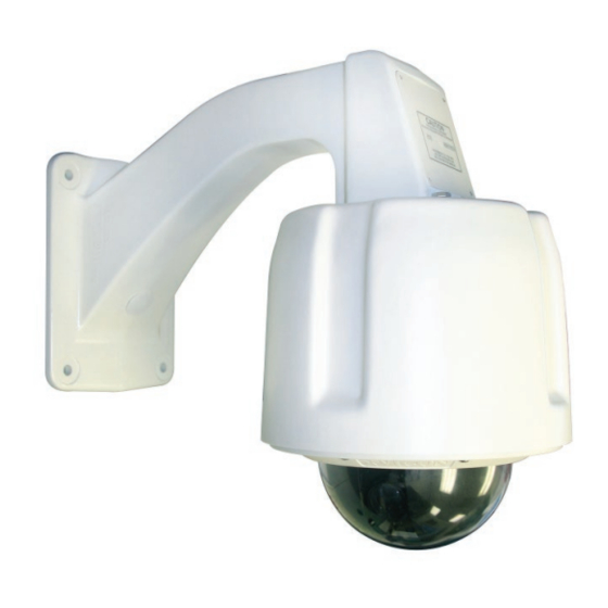
Surveyor® HD Network
Pressurized Camera Domes
Vicon Industries Inc.
Tel: 631-952-2288 Fax: 631-951-2288 Toll Free: 800-645-9116
24-Hour Technical Support: 800-34-VICON (800-348-4266) UK: 44/(0) 1489-566300
Vicon Industries Inc. does not warrant that the functions contained in this equipment will meet your requirements or that the
operation will be entirely error free or perform precisely as described in the documentation. This system has not been designed
to be used in life-critical situations and must not be used for this purpose.
www.vicon-security.com
Document Number: 8009-8214-60-06
Issued: 514
Product specifications subject to change without notice.
Copyright © 2013 Vicon Industries Inc. All rights reserved.
Advertisement
Table of Contents

Subscribe to Our Youtube Channel
Related Manuals for Vicon XX214-60-06


Summary of Contents for Vicon XX214-60-06
- Page 1 24-Hour Technical Support: 800-34-VICON (800-348-4266) UK: 44/(0) 1489-566300 Vicon Industries Inc. does not warrant that the functions contained in this equipment will meet your requirements or that the operation will be entirely error free or perform precisely as described in the documentation. This system has not been designed to be used in life-critical situations and must not be used for this purpose.
-
Page 2: Fcc Notice
FCC Notice Note: Complies with Federal Communications Commission Rules & Regulations Part 15, Subpart B for a Class A digital device. WARNING This equipment generates and uses radio frequency energy and if not installed and used properly, that is, in strict accordance with the manufacturer’s instruction, may cause interference to radio and television reception. - Page 3 6. Cleaning - (Do not use caustic, abrasive or aerosol The product shows a significant change in performance. cleaners) 21. Replacement Parts - Use only Vicon specified replacement For units that CAN BE DISCONNECTED from the power parts or an approved equivalent to prevent unit damage and source, use a damp cloth for cleaning.
-
Page 4: Chapter 1 Introduction
General Information Chapter 1 Introduction This chapter provides general information about the Surveyor® HD and Surveyor SD Pressurized Network Dome. Refer to the end of this chapter for the organization of the rest of this manual. The chapter consists of the following topics: Topic Page General Information... -
Page 5: General Information
H.264 or M-JPEG compression. The dome supports ONVIF open architecture connectivity to enable integration into third party Video Management Systems (VMS), including Vicon’s ViconNet. The Surveyor HD/SD is designed for easy installation and serviceability. The entire drive assembly simply snaps into the housing. When removed, the mechanism retains all programmed functions in its on-board memory. - Page 6 General Information Table 1: Models and Descriptions Model Environment Resolution Mount Optical Zoom/ Lower Number Type Digital Zoom Dome Type SN130P Outdoor/ 1.3 megapixel Pendant Clear Pressurized SN220P-L Outdoor/ 2 megapixel Pendant Clear Pressurized Add a –FM to the model number for a multi-mode fiber version and a –FS to the model number for a single mode fiber model.
- Page 7 Chapter 1 Introduction Organization of this Manual Chapter Description Introduction: Provides general information about the Surveyor HD/SD Pressurized Network Dome Installation: Describes how to install the Surveyor HD/SD Pressurized Network Dome and wiring instructions Configuration and Operation: Describes how to, configure and operate the Surveyor HD/SD Pressurized Network Dome Maintenance and Reference: Describes basic system...
- Page 8 Installation Chapter 2 Installation This chapter provides installation information for the Surveyor HD/SD Pressurized Network Dome. The chapter consists of the following topics: Topic Page Installation ...................... 2-2 Quick Installation ................... 2-6 Detailed Installation ..................2-7 Uninstalling ....................2-28 Surveyor HD Pressurized Network Dome XX214-60...
-
Page 9: Installation
Chapter 2 Installation Installation Caution This unit should only be installed by a qualified technician using common hand tools and approved materials and wiring methods in accordance with the National Electrical Code ANSI/NFPA 70, state and local wiring codes. All interconnecting equipment or accessories must be UL Listed. -
Page 10: Accessory Kits
Optionally, a 23-pin prefabricated cable assembly may be purchased separately for ease of wiring. Unpacking All Vicon equipment is tested and inspected before leaving the factory. It is the carrier’s responsibility to provide suitable delivery. Inspect the cartons upon delivery and, if damage is present, make detailed notes on the carrier’s bill. - Page 11 Chapter 2 Installation Note By default, when the pressure in the housing dips below 1/2 psig an On Screen Display message appears stating “Low Pressure Warning.” Alternatively, this alarm warning may be sent to the CPU by enabling the alarm in the camera dome’s menu. When this is activated, the On Screen Display message will not appear.
-
Page 12: Mac Address
Installation MAC Address Surveyor HD Pressurized Network Dome XX214-60... -
Page 13: Quick Installation
Chapter 2 Installation Quick Installation XX214-60 Surveyor HD Pressurized Network Dome... -
Page 14: Detailed Installation
23-pin cable assembly can be used. Use the applicable sub-section to install the correct connector type included. Wall Mount Method Use this method to install, wire and configure a unit with a Vicon wall mount. Refer to the Figure below as required. Wall Mount Installation Installing the Wall Mount 1. - Page 15 Chapter 2 Installation 3. Place a bead of silicone sealant around the wall mount mounting flange, press it to the surface and line up the flange holes with drilled holes. Install the appropriate 3/8 in. (9.5 mm) stainless steel hardware and fasten snugly.
- Page 16 Detailed Installation Installing the 23-Pin Connector Assembly (If the prefabricated 23-pin cable assembly is used.) 6. Use the 23-pin cable assembly purchased separately. It should resemble the assembly of Figure below. a. Identify the cables required for attaching to the 23-pin connector assembly.
- Page 17 2-10 Chapter 2 Installation Note The wire color code may not match the Figure. Verify each wire is labeled with a function. DO NOT remove the labels. Use the wire labels for absolute reference. Wiring and Assembling the 23-Pin Connector (Using the discrete 23-pin connector with crimp pins provided.) Assemble the 23-pin connector as shown in Figure below.
- Page 18 2-11 Detailed Installation a. Identify the cables required for attaching to the 23-pin connector. There should be a minimum of three (3), power (18 to 32 VAC); pins A, C, D, P, T, L, M, J, K, X and U are not used.
- Page 19 2-12 Chapter 2 Installation Identify each wire on the site installed cables and label it (A, B, C, D, etc.) in accordance with the labels on the 23-pin connector assembly wires. Assembling the connector is complete. Caution Overheating the shrink wrap tubing can result in damage to the tubing and the entire 23-pin connector assembly.
- Page 20 2-13 Detailed Installation Housing Connections All the necessary connections are provided at the top of the housing, including the 23-pin connector and connectors for IP video/data transmission. Refer to the figure below. Preparing the Camera Drive Open the box containing the camera drive assembly and remove it. Setting the DIP Switches There are two DIP switches that must be set on the pressurized Surveyor HD.
- Page 21 2-14 Chapter 2 Installation DIP Switch Location on CI Board Caution Changing the positions on the DIP switch on the Main board should only be done by a qualified person. Positions 1 is used only if it is necessary to force the unit into default setup if network or system connections are lost.
- Page 22 2-15 Detailed Installation Position 7 – Set password. OFF = Default Position (default password is password or 1234). ON = Set new password; must be set OFF after reboot and before next power up. Position 8 – System Mode. OFF = Default Position, ViconNet Mode ON = ONVIF/NTCIP Mode.
- Page 23 2-16 Chapter 2 Installation holes. Install the eight (8) screws and tighten only with a torque wrench set for 15-in. lb (170-N cm) of force. Use an alternating (star) pattern to tighten all the screws. Pressurizing the Housing Assembly Refer to Figure below as needed. Reattach the previously removed service cover to the service opening using the four (4) captive screws.
- Page 24 2-17 Detailed Installation Warning Do not use any gas type other than dry Nitrogen. The use of Shop Air can introduce moisture into the housing assembly that can damage it over time. Proceed to the Operation section of this manual. Communication Ports If using NTCIP protocol, communicate to the Surveyor HD/SD using ports 3000/UDP or 3001/TCP.
- Page 25 2-18 Chapter 2 Installation Pipe Mount Method Use this method to install, wire and configure a pipe mounted unit. Refer to Figure below as required. Installing the Pipe Mount Select a suitable mounting location and verify that the site wiring is present.
- Page 26 2-19 Detailed Installation Installing the 23-Pin Connector Assembly (If the prefabricated 23-pin cable assembly is used.) Use the 23-pin cable assembly purchased separately. It should resemble the assembly of Figure below. a. Identify the cables required for attaching to the 23-pin connector assembly.
- Page 27 2-20 Chapter 2 Installation Note The wire color code may not match the Figure. Verify each wire is labeled with a function. DO NOT remove the labels. Use the wire labels for absolute reference. Wiring and Assembling the 23-Pin Connector (Using the discrete 23-pin connector with crimp pins provided.) 7.
- Page 28 2-21 Detailed Installation a. Identify the cables required for attaching to the 23-pin connector. There should be a minimum of three (3), power (18 to 32 VAC); pins A, C, D, P, T, L, M, J, K, X and U are not used.
- Page 29 2-22 Chapter 2 Installation Identify each wire on the site installed cables and label it (A, B, C, D, etc.) in accordance with the labels on the 23-pin connector assembly wires. Assembling the connector is complete. Caution Overheating the shrink wrap tubing can result in damage to the tubing and the entire 23-pin connector assembly.
- Page 30 2-23 Detailed Installation Housing Connections All the necessary connections are provided at the top of the housing, including the 23-pin connector and connectors for IP video/data transmission. Refer to the figure below. Preparing the Camera Drive Open the box containing the camera drive assembly and remove it. Setting the DIP Switches There are two DIP switches that must be set on the pressurized Surveyor HD.
- Page 31 2-24 Chapter 2 Installation DIP Switch Location on CI Board Caution Changing the positions on the DIP switch on the Main board should only be done by a qualified person. Positions 1 is used only if it is necessary to force the unit into default setup if network or system connections are lost.
- Page 32 2-25 Detailed Installation Position 7 – Set password. OFF = Default Position. ON = Reset to default password (password or 1234); must be reset to OFF after reboot and before next power up. Position 8 – System Mode. OFF = Default Position, ViconNet Mode. ON = ONVIF/NTCIP Mode.
- Page 33 2-26 Chapter 2 Installation Pressurizing the Housing Assembly Refer to Figure below as needed. Reattach the previously removed service cover to the service opening using the four (4) captive screws. Using a regulated source of dry Nitrogen gas with the proper Schraeder type fill fitting, as shown in Figure below, regulate the gas pressure to 10.0 psi (0.68 atm or bars).
- Page 34 2-27 Detailed Installation Warning Do not use any gas type other than dry Nitrogen. The use of Shop Air can introduce moisture into the housing assembly that can damage it over time. Proceed to the Operation section of this manual. Communication Ports If using NTCIP protocol, communicate to the Surveyor HD/SD using ports 3000/UDP or 3001/TCP.
-
Page 35: Uninstalling
2-28 Chapter 2 Installation Uninstalling If it becomes necessary to uninstall to pressurized Surveyor HD, follow the steps below. Warning Before starting to uninstall the unit, be sure to release all the pressure through the fill valve on the side of the unit. 1. - Page 36 Configuration and Operation Chapter 3 Configuration and Operation This chapter will describe how to wire, configure and operate the Surveyor HD Pressurized Network Dome. The chapter consists of the following topics: Topic Page Typical Relay and Alarm Connections Configuring and Operating the Pressurized Surveyor HD Network Dome Surveyor HD Pressurized Network Dome XX214-60...
-
Page 37: Typical Relay And Alarm Connections
Chapter 3 Configuration and Operation Typical Relay and Alarm Connections Alarm input and relay output type signals are also carried on individually- shielded twisted-pair cable sets. The signals are defined in the following descriptions. Note The twisted-pair cable should have a wire gauge (AWG) of 24-16 and a category type of 2, 3, 4, 5 or better. - Page 38 Configuration and Operation The “active” state can be programmed through the Surveyor HD web browser interface. These signals are connected to terminal block TB1. Alarm signals can be programmed for their status (enabled/disabled), active level definition (high/low), action/reset function (none, preset, aux on, aux off or tour), acknowledgment mode (automatic, momentary or manual) and report status (yes/no).
- Page 39 Chapter 3 Configuration and Operation Configuring and Operating the Pressurized Surveyor HD Network Dome Following the completion of the installation, the pressurized Surveyor HD is setup and operated through a web browser interface. Refer to the Web Browser instruction manual XX214-40 for detailed information on camera configuration.
- Page 40 Pressurized Network Dome. The chapter consists of the following topics: Topic Page 4-2 Operation 4-3 Maintenance 4-4 Shipping Instructions 4-5 Network Cable 4-6 Technical Specifications 4-9 Vicon Standard Equipment Warranty Surveyor HD Pressurized Network Dome XX214-60...
- Page 41 The Pressurized Surveyor HD Camera Dome operates on an Onvif compliant platform that allows it to work with any Onvif compliant Video Management System (VMS), including Vicon’s ViconNet. Refer to the documentation for those operating systems to setup the Surveyor HD. After the camera dome is configured according to the requirements for the specific video management system, it is controlled through the Web Browser.
-
Page 42: Fuse Replacement
Operation, Maintenance and Reference Maintenance The Pressurized Surveyor HD requires no scheduled maintenance; however, the lower domes require occasional cleaning. All domes require careful handling and occasional cleaning. Care and Cleaning of Smoked and Clear Acrylic Domes 1. Always handle the lower dome by the flange and avoid touching the inside surface. -
Page 43: Shipping Instructions
Shipping Instructions Use the following procedure when returning a unit to the factory: 1. Call or write Vicon for a Return Authorization (R.A.) at one of the locations listed below. Record the name of the Vicon employee who issued the R.A. -
Page 44: Network Cable
Network Cable Caution Careful selection of proper cable is essential to obtain the best performance. Vicon assumes no responsibility for poor performance when cables other than the recommended types, or equivalent, are used. Materials Use pure copper stranded conductors to obtain a low DC resistance. The preferred insulation and cable jacket is Polyvinyl chloride (PVC). -
Page 45: Technical Specifications
1280 x 720 @ 30 fps. 2 megapixel version: 1920 x 1080 @ 30 fps.. Programming Interface: ONVIF or Vicon API. Protocols: IP, HTTP, RTSP/RTP, DNS client, FTP, SMTP, PPPoE, TCP/IP, DHCP, UDP, Multicast, NTP, DDNS, IGMP, ARP, SOAP, WSDL, WS- Discovery. - Page 46 Operation, Maintenance and Reference Backlight Compensation: On/Off, selectable. Iris Control: Automatic. Digital Noise Reduction: On/Off, selectable. Wide Dynamic Range: On/Off, selectable. Video Focus: Automatic/Manual (near-far). White Balance: Automatic/Manual; Red/Blue gain adjustable. Shutter Speed: 1.3 megapixel version: Automatic/Manual: 1/4 - 10,000 sec. 2.0 megapixel version: Automatic/Manual: 1/0.75 - 30,000 sec.
- Page 47 Operation, Maintenance and Reference e enable/disable. Report state (report on/off). Active state (high/low). Mode (manual, momentary or automatic) with programmable dwell time control. Set and reset action (preset solve, relay on/off, tour, autotour). Alarm titling. Alarm Output: 1 relay, momentary or latching. Control Display: Web browser interface.
-
Page 48: Vicon Standard Equipment Warranty
“autopan” or “tour” modes of operation. Such continuous operation is outside the scope of this warranty. Any product sold as “special” or not listed in Vicon’s commercial price list: One year from date of original retail purchase. - Page 49 Vicon Industries Inc. For office locations, visit the website: www.vicon-security.com...
Need help?
Do you have a question about the XX214-60-06 and is the answer not in the manual?
Questions and answers