ABB TTR200 Operating Instructions Manual
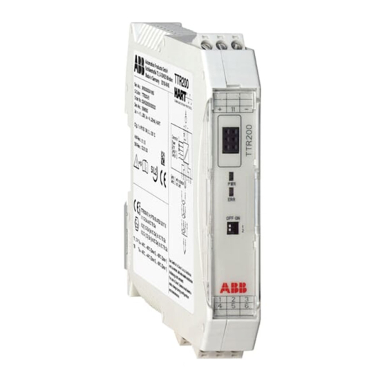
Rail mounted temperature transmitter
Hide thumbs
Also See for TTR200:
- Operating instruction (24 pages) ,
- Safety instructions (24 pages) ,
- Additional instructions (20 pages)

Related Manuals for ABB TTR200


Summary of Contents for ABB TTR200
- Page 1 Operating Instruction Rail Mounted Temperature Transmitter OI/TTR200-EN TTR200 Pos: 1 /Titelblätter / Copyright/BA-IA/Temperatur/TTR200 @ 15\mod_1195562171781_3101.doc @ 141598...
- Page 2 Tel.: +49 551 905-534 Fax: +49 551 905-555 CCC-support.deapr@de.abb.com © Copyright 2008 by ABB Automation Products GmbH Subject to change without notice This document is protected by copyright. It assists the user with the safe and efficient operation of the device.
-
Page 3: Table Of Contents
Pin configuration............................14 5.2.1 Supply voltage / sensor connection ......................14 Block diagram...............................15 Standard application.............................16 Electrical interconnection in explosion risk area ..................18 5.5.1 Installation in ignition protection areas....................19 5.5.2 Zone 0 ..............................19 5.5.3 Zone 1 (0)..............................20 5.5.4 Zone 1 (20)............................21 OI/TTR200-EN TTR200... - Page 4 Configuration via DTM ..........................24 7.1.4 Configuration via EDD...........................24 Write protection ............................24 Sensor error adjustment (TTR200 DTM Adjust function) TTR200 ..............25 D/A analog output compensation (4 and 20 mA trim) ..................25 HART variables ............................26 Communication / HART tag / Device address....................26 Description of parameters ..........................27...
-
Page 5: Safety
Pos: 4.5 /Sicherheit/Allgemein/Hinweis zur bestimmungswidrigren Verwendung (Wartung/Reparatur) @ 0\mod_1129707002440_3101.doc @ 3240 Repairs, alterations and enhancements or the installation of replacement parts is only permissible as far as described in the manual. Further actions must be verified with ABB Automation Products GmbH. Excluded from this are repairs performed by ABB-authorized specialist shops. -
Page 6: Technical Limits
The symbol indicates a possibly damaging situation. If it is not avoided, the product or something in its area can be damaged. Important The symbol indicates operator tips or especially useful information. This is not a message for a dangerous or damaging situation. Pos: 4.12 /======= Seitenumbruch ======== @ 0\mod_1126532365768_3101.doc @ 3830 TTR200 OI/TTR200-EN... -
Page 7: Name Plate
The temperature range on the name plate (7) refers only to the permissible ambient temperature range for the transmitter and not to the measuring element used in the measuring inset. Pos: 4.15 /======= Seitenumbruch ======== @ 0\mod_1126532365768_3101.doc @ 3830 OI/TTR200-EN TTR200... -
Page 8: Operator Liability
Before the use of corrosive and abrasive measuring fluid, the operator must clarify the resistance of all parts that come into contact with the fluid to be measured. ABB will gladly support you with the selection, however, cannot accept any liability. -
Page 9: Information On Weee Directive 2002/96/Ec (Waste Electrical And Electronic Equipment)
WEEE directive 2002/96/EC. Proper disposal prevents negative effects on people and the environment, and supports the reuse of valuable raw materials. If it is not possible to dispose of old equipment properly, ABB Service can accept and dispose of returns for a fee. -
Page 10: Operating Safety Information
(PBB) and polybrominated diphenyl ethers (PBDE) (also known as hazardous substances with restricted uses). The products provided to you by ABB Automation Products GmbH do not fall within the current scope of the directive on waste from electrical and electronic equipment according to ElektroG. -
Page 11: Use In Areas Requiring Ignition Protection
The approvals for use of the TTR200 temperature transmitter in explosion-protection areas can be found in the section "Explosion-protection relevant information" in the operating instructions. Level of protection The adapters for the model TTR200 temperature transmitter meet the IP 20 level of protection in accordance with IEC 60529:1989. Electrostatic charging When using the transmitter in zone 0, make sure you prevent electrostatic charging of the TTR200-E1H temperature transmitter (observe warnings on equipment). -
Page 12: Design And Function
Design and function Pos: 8 /Überschriften/1/A - C/Aufbau und Funktion @ 0\mod_1129797620733_3101.doc @ 3140 Design and function Pos: 9 /Aufbau und Funktion/Temperatur/TTR200/Aufbau und Funktion @ 15\mod_1195565201671_3101.doc @ 141694 Digital transmitters communication-ready devices with microprocessor-controlled electronics. For bidirectional communication, an FSK signal is superimposed on the 4 … 20 mA output signal via the HART protocol. -
Page 13: Electrical Connection
The signal cable wires must be provided with wire end sleeves. The slotted screws of the connection terminals are tightened with a size 1 screwdriver (3.5 mm). Pos: 14.3 /Elektrischer Anschluss/Temperatur/TTR200/Hinweis zu Leitungsmaterial TTR200 @ 15\mod_1195568460984_3101.doc @ 141814 Conductor material •... -
Page 14: Pin Configuration
RTD, 3-wire circuit RTD, 4-wire circuit Pos: 14.8 /Elektrischer Anschluss/Temperatur/TTR200/Anmerkung zu Anschlussplan (BA) @ 18\mod_1205827740529_3101.doc @ 170993 Note Terminal 11: Measurement of 4 … 20 mA output current without opening / interrupting the current loop (see chapter 5.3 Block diagram ) •... -
Page 15: Block Diagram
Electrical connection Pos: 14.10 /Überschriften/1.1/1-spaltig/A - C/Blockschaltbild @ 16\mod_1199270222218_3101.doc @ 147214 Block diagram Pos: 14.11 /Technische Daten / Datenblatt/Temperatur/TTR/Technische Daten/Blockschaltbild @ 15\mod_1194870440921_3101.doc @ 139841 Sensor TTR200 Power supply 3,5 kV DC ( 2,5 kV AC 60s) A00202 Fig. 4 24-bit A/D converter... -
Page 16: Standard Application
Electrical connection Pos: 14.13 /Überschriften/1.1/1-spaltig/S - U/Standardanwendung @ 16\mod_1198073912500_3101.doc @ 146614 Standard application Pos: 14.14 /Elektrischer Anschluss/Temperatur/TTR200/Signal-/Versorgungsanschluss Teil 1 @ 16\mod_1198168131718_3101.doc @ 146748 Field Control room Fig. 5 A Transmitter B Power supply / SPS input with supply When connecting transmitters and power supplies, observe the following specification: ≤... - Page 17 : Minimum operating voltage of transmitter (refer to technical data for transmitter) Mmin : Minimum supply voltage of repeater power supply / SPS input Smin Line resistance between transmitter and power supply Resistance for HART functionality Pos: 14.15 /======= Seitenumbruch ======== @ 0\mod_1126532365768_3101.doc @ 3830 OI/TTR200-EN TTR200...
-
Page 18: Electrical Interconnection In Explosion Risk Area
Pos: 14.16 /Überschriften/1.1/1-spaltig/D - F/Elektrische Zusammenschaltung im explosionsgefährdeten Bereich @ 16\mod_1198154339484_3101.doc @ 146654 Electrical interconnection in explosion risk area Pos: 14.17 /Elektrischer Anschluss/Temperatur/TTR200/Elektrische Zusammenschaltung im explosionsgeschützten Bereich @ 16\mod_1198162640515_3101.doc @ 146700 Special interconnections are required for use in hazardous areas depending on the safety requirements. -
Page 19: Installation In Ignition Protection Areas
Electrical connection Pos: 14.19 /Elektrischer Anschluss/Temperatur/TTR200/Installation im explosionsgefährdetem Bereich @ 15\mod_1195572347828_3101.doc @ 141910 5.5.1 Installation in ignition protection areas Transmitters can be installed in a wide variety of industrial sectors. Systems that requires ignition protection are divided into zones. As a result, different instruments are also required. -
Page 20: Zone 1 (0)
For instruments in zone 1, the input for the repeater must be at minimum in [EEx ib] design. The sensor must be used by the user in accordance with applicable ignition-protection standards. It can be installed in zone 1 or zone 0. TTR200 OI/TTR200-EN... - Page 21 For instruments in zone 1, the input for the repeater must be at minimum in [EEx ib] design. The sensor must be used by the user in accordance with applicable ignition-protection standards. It can be installed in zone 0, zone 1 or zone 20. OI/TTR200-EN TTR200...
-
Page 22: Zone 2
For instruments in zone 2, the transmitter must be installed in its own housing with a minimum of IP 54 level of protection. Ensure that in case of a disturbance the supply voltage cannot exceed 40 % of the normal voltage. Pos: 15 /======= Seitenumbruch ======== @ 0\mod_1126532365768_3101.doc @ 3830 TTR200 OI/TTR200-EN... -
Page 23: Startup Operation
Pos: 19.1 /Überschriften/1/J - L/Kommunikation und Konfiguration @ 1\mod_1144747059078_3101.doc @ 6033 Communication and configuration Pos: 19.2 /Überschriften/1.1/1-spaltig/J - L/Konfigurationsarten @ 0\mod_1140521210140_3101.doc @ 3196 Configurations Pos: 19.3 /Konfiguration, Parametrierung/Temperatur/TTR200/Konfigurationsarten TTR200 / HART- Kommunikation @ 15\mod_1195573382203_3101.doc @ 141935 Transmitters can be configured as follows: • via HART protocol and handheld terminal •... -
Page 24: Configuration With The Handheld Terminal
Pos: 19.11 /Konfiguration, Parametrierung/Temperatur/TTR200/Schreibschutz @ 15\mod_1195574376984_3101.doc @ 141982 To protect the device setup, the TTR200 provides write protection for software and hardware. You can enable or disable the hardware write protection via the 2-pin DIP switch on the front of the unit (see Fig. -
Page 25: Sensor Error Adjustment (Ttr200 Dtm Adjust Function) Ttr200
Error compensation for the superordinate system is possible at the LRL with 4 mA or 20 mA. (Single point error correction: Offset or two-point error correction offset + linear gradient) The D/A analog output compensation can be accessed in the TTR200 DTM via the path Device / Maintenance / Adjust. -
Page 26: Hart Variables
Pos: 19.13.8 /Überschriften/1.1/1-spaltig/J - L/Kommunikation / HART-Tag / Geräte-Adressierung @ 8\mod_1174410351609_3101.doc @ 73867 Communication / HART tag / Device address Pos: 19.13.9 /Konfiguration, Parametrierung/Temperatur/TTR200/Kommunikation / HART-Tag / Geräte-Adressierung @ 15\mod_1195815541078_3101.doc @ 142514 For ease of identification, each HART device features a configurable 8-digit HART tag. -
Page 27: Description Of Parameters
Communication and configuration Pos: 19.14 /Überschriften/1.1/1-spaltig/P - R/Parameterbeschreibung @ 8\mod_1174488666890_3101.doc @ 73934 Description of parameters Pos: 19.15 /Konfiguration, Parametrierung/Temperatur/TTR200/Parameterbeschreibung @ 15\mod_1195815792125_3101.doc @ 142558 Device Description DTM parameters Effective range parameters Activates write protection for the <Basic Parameters> Yes: locked Write protection entire device. - Page 28 <Device> <Maintenance> mode: Point-to-point communication, (Multidrop) <Poll Address / Tag> 4 ... 20 mA output signal address = 1 ... 15 conforms to HART multidrop operating mode output signal 3.6 mA only the digital HART readings are available TTR200 OI/TTR200-EN...
-
Page 29: Factory Settings
3,5 ... 23,6 mA corresponding to the value specified Pos: 19.16 /==== Leeres Modul mit einer Absatzmarke, IM, 1-spaltig ==== @ 14\mod_1194422545687_0.doc @ 136717 Pos: 19.17 /Konfiguration, Parametrierung/Temperatur/TTR200/Werkseinstellungen @ 16\mod_1196672946593_3101.doc @ 143933 7.7.1 Factory settings The transmitter is configured in the factory. The following table contains the values for the individual parameters. -
Page 30: Ttr200 Dtm Diagnostic Information
<Reset> button. Analog output / LED diagnostic information The TTR200 features a green and a red diagnostic LED for fault signaling. The green LED indicates that the supply voltage is connected and the red LED provides fault information about the sensor, sensor lead and unit;... -
Page 31: Maintenance / Repair
Pos: 21.3 /Wartung / Reparatur/Allgemein/1.1 Reinigung @ 0\mod_1132066200463_3101.doc @ 3550 Cleaning When cleaning the exterior of meters, make sure that the cleaning agent used does not corrode the housing surface and the seals. Pos: 22 /======= Seitenumbruch ======== @ 0\mod_1126532365768_3101.doc @ 3830 OI/TTR200-EN TTR200... -
Page 32: Explosion-Protection Relevant Information
10.2 TTR200-E2… (non-incendive) Pos: 25 /Technische Daten / Datenblatt/Temperatur/TTR/Zertifizierungen @ 15\mod_1194876510140_3101.doc @ 139987 Approved for use in zone 2. CE mark: The TTR200 meets all requirements for the CE mark in accordance Designation: with IEC 61326 (2006). • II 3 G EEx n A II T6... -
Page 33: Technical Data
(offset adjustment) via two point adjustment Sensor fault signaling RTD sensor: Short circuit and wire break Linear resistance measurement: Wire break Thermocouple: Wire break Linear voltage measurement: Wire break Pos: 28.5 /======= Spaltenumbruch ======== @ 0\mod_1132937966324_3101.doc @ 3831 OI/TTR200-EN TTR200... -
Page 34: Power Supply (Polarity Safe)
Fig. 13 150 kHz … 80 MHz 10 V < 0,5% TTR200 HART communication - Surge resistor TTR200 in EEx ia design between the supply lines no malfunction 0,5 kV Max. power consumption Line to earth no malfunction 1 kV P = U x 0.022 mA... -
Page 35: Appendix
EMC directive 89/336/EEC Ex approvals By placing the Ex mark on the name plate, ABB Automation Products GmbH also declares its conformance with the following directive: ATEX directive 94/9/EC Pos: 36 /Hinweise/Wichtig/Wichtig - Verweis auf Download-Bereich @ 21\mod_1215086830219_3101.doc @ 204693... - Page 36 Appendix Pos: 38 /Zertifikate/Temperatur/EG-Konformatätserklärung_TTR200/300 @ 18\mod_1204548362612_0.doc @ 166374 Pos: 39 /======= Seitenumbruch ======== @ 0\mod_1126532365768_3101.doc @ 3830 TTR200 OI/TTR200-EN...
- Page 37 Which substances have had contact with the device? We hereby certify that the devices/parts shipped were cleaned and are free from any dangerous or poisonous materials. City, Date Signature and company stamp Pos: 41 /======= Seitenumbruch ======== @ 0\mod_1126532365768_3101.doc @ 3830 OI/TTR200-EN TTR200...
-
Page 38: Index
Electrical installation safety information.....9 Permits and certifications.........35 Electrical interconnection.........18 Personnel qualification..........8 Electrostatic charging ..........11 Pin configuration ............14 EMC directive............35 Explosion-protection relevant information ....32 Resistance ...............33 Returning devices ............8 Factory settings............29 Safety.................5 General information ..........31 Safety information on deinstallation......10 TTR200 OI/TTR200-EN... - Page 39 Index Sensor connections ..........33 Thermocouples ............33 Sensor error adjustment (TTR200 DTM Adjust Transmission characteristics ........33 function)..............25 Transport safety information ........9 Sensor short-circuit..........33 TTR200 DTM diagnostic information .......30 Sensor wire break ............33 Types ...............33 Simulation mode ............33 Standard application ..........16 Use in areas requiring ignition protection ....11 Startup Operation.............23...
- Page 40 ABB has Sales & Customer Support The Company’s policy is one of continuous product expertise in over 100 countries worldwide. improvement and the right is reserved to modify the information contained herein without notice. www.abb.com/temperature Printed in the Fed. Rep. of Germany (08.2008) ©...
Need help?
Do you have a question about the TTR200 and is the answer not in the manual?
Questions and answers