Table of Contents
Advertisement
Quick Links
Advertisement
Table of Contents

Subscribe to Our Youtube Channel
Related Manuals for Crestron TPMC-9L


Summary of Contents for Crestron TPMC-9L
- Page 1 Crestron TPMC-9L 9” Wall Mount Touch Screen Operations & Installation Guide...
- Page 2 States and/or other countries. Other trademarks, registered trademarks, and trade names may be used in this document to refer to either the entities claiming the marks and names or their products. Crestron disclaims any proprietary interest in the marks and names of others. Crestron is not responsible for errors in typography or photography.
-
Page 3: Table Of Contents
Crestron TPMC-9L 9” Wall Mount Touch Screen Contents 9” Wall Mount Touch Screen: TPMC-9L Introduction ..........................1 Features and Functions ....................1 Applications......................... 4 Specifications ......................5 Physical Description ....................8 Setup ............................12 Network Wiring ......................12 Identity Code ......................12 Configuring the Touch Screen ................... -
Page 5: 9" Wall Mount Touch Screen: Tpmc-9L
9” Wall Mount Touch Screen: TPMC-9L Introduction ® The TPMC-9L Wall Mount Touch Screen from Crestron delivers high end style and performance in a compact, cost effective flush mount design. Featuring a generous 9” (~229 mm) widescreen display, advanced touch screen graphics, H.264 ®... - Page 6 Streaming video capability makes it possible to view security cameras and other video sources right on the touch screen. Native support for H.264 and MJPEG formats allows the TPMC-9L to display live from an IP camera, a streaming server ®...
- Page 7 TPMC-9L’s integrated microphone and speakers. Audio Feedback Customized audio files can be loaded on the TPMC-9L to add another dimension to the touch screen graphics using personalized sounds, button feedback and voice prompts.
-
Page 8: Applications
9” Wall Mount Touch Screen Crestron TPMC-9L Applications The following diagram shows a TPMC-9L in a typical application. TPMC-9L in a Typical Application 4 • 9” Wall Mount Touch Screen: TPMC-9L Operations & Installation Guide – DOC. 7030F... -
Page 9: Specifications
Crestron TPMC-9L 9” Wall Mount Touch Screen Specifications Specifications for the TPMC-9L are listed in the following table. TPMC-9L Specifications SPECIFICATION DETAILS Touch Screen Display Display Type TFT active matrix color LCD Size 9 inch (229 mm) diagonal Aspect Ratio... - Page 10 Backlit Button Faceplate with Custom T_ENGRAVED Engraving (specify color) ® VMK-WIN Touchpoint Virtual Mouse & Keyboard ® Software for Windows WMKB-6L Replacement Wall Mount Clips (Continued on following page) 6 • 9” Wall Mount Touch Screen: TPMC-9L Operations & Installation Guide – DOC. 7030F...
- Page 11 Post-Construction Wall Mount Kit with Mud Ring WMKT-9L Lectern or Post-Construction Wall Mount Kit with Trim Ring Refer to “Identity Code” which starts on page 12 for details. 9” Wall Mount Touch Screen: TPMC-9L • 7 Operations & Installation Guide – DOC. 7030F...
-
Page 12: Physical Description
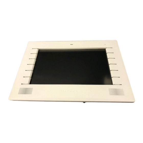
Physical Description This section provides information on the connections, controls and indicators available on the TPMC-9L. TPMC-9L Physical View TPMC-9L Physical View (With No-Button Faceplate) 8 • 9” Wall Mount Touch Screen: TPMC-9L Operations & Installation Guide – DOC. 7030F... - Page 13 Crestron TPMC-9L 9” Wall Mount Touch Screen TPMC-9L Overall Dimensions (Front and Side Views, with Faceplate) 1.86 in (48 mm) 0.38 in (10 mm) Light Sensor Microphone 0.39 in (10 mm) 7.52 in (191 mm) 10.83 in (275 mm) TPMC-9L Overall Dimensions (Front and Side Views) 10.69 in...
- Page 14 Input level: 1 Vp-p nominal, 1.5 Vp-p maximum; Maximum dc offset: ± 2 volts; Connects to any conventional coax video source (Continued on following page) 10 • 9” Wall Mount Touch Screen: TPMC-9L Operations & Installation Guide – DOC. 7030F...
- Page 15 RX - RX + 1. Interface connectors for VIDEO and NET ports are provided with the unit. 2. Balanced and unbalanced video inputs are mutually exclusive. 9” Wall Mount Touch Screen: TPMC-9L • 11 Operations & Installation Guide – DOC. 7030F...
-
Page 16: Setup
The IP ID is set within the TPMC-9L’s IP table using the internal setup menu (refer to “IP Table” which starts on page 16). IP ID may also be set from a PC via Crestron Toolbox. For information on setting an IP table, refer to the Crestron Toolbox help file. -
Page 17: Configuring The Touch Screen
NOTE: The only connection required to configure the touch screen is power. Refer to “Hardware Hookup” which starts on page 31 for details. NOTE: The TPMC-9L can take up to 45 seconds to boot to a display after initial power up. - Page 18 Touch Ethernet to enter the Ethernet Setup Menu, shown in the illustration below. Ethernet Setup Menu The Ethernet Setup Menu displays information about the Link Status, Control Connection, DHCP, MAC address, IP address, subnet, default gateway, primary 14 • 9” Wall Mount Touch Screen: TPMC-9L Operations & Installation Guide – DOC. 7030F...
- Page 19 Primary WINS or Static Secondary WINS, touch Edit DNS Servers on the IP Address screen. The IP Address screen changes to show these addresses, as shown in the illustration below. 9” Wall Mount Touch Screen: TPMC-9L • 15 Operations & Installation Guide – DOC. 7030F...
- Page 20 IP Table From the main Setup menu, touch IP Table to enter the Control System Interface menu, shown in the illustration below. Control System Interface Menu 16 • 9” Wall Mount Touch Screen: TPMC-9L Operations & Installation Guide – DOC. 7030F...
- Page 21 Touch OK to accept the entry or CANCEL to cancel the entry. This hides the on- screen keyboard and returns the display to the Edit IP Table Entry screen. 9” Wall Mount Touch Screen: TPMC-9L • 17 Operations & Installation Guide – DOC. 7030F...
- Page 22 Touch OK to confirm the removal or touch CANCEL to cancel the removal. The display returns to the Control System Interface menu (refer to the second illustration on page 16). 18 • 9” Wall Mount Touch Screen: TPMC-9L Operations & Installation Guide – DOC. 7030F...
- Page 23 There is also a Restore Defaults button to return to factory settings and a window to display video. Touch the video window for a full screen video display, as shown in the illustration below. Full Screen Video Display 9” Wall Mount Touch Screen: TPMC-9L • 19 Operations & Installation Guide – DOC. 7030F...
- Page 24 Play Test Wave button. Touch Return to go back to the main Setup menu. Cresnet From the main Setup menu, touch Cresnet to enter the Cresnet Interface screen, shown in the illustration below. Cresnet Interface Screen 20 • 9” Wall Mount Touch Screen: TPMC-9L Operations & Installation Guide – DOC. 7030F...
- Page 25 Touch Test Patterns to display a selection of test pattern options, as shown in the illustration below. 9” Wall Mount Touch Screen: TPMC-9L • 21 Operations & Installation Guide – DOC. 7030F...
- Page 26 After calibration, the display returns to the screen shown above. Touch Return to go back to the Diagnostics menu. 22 • 9” Wall Mount Touch Screen: TPMC-9L Operations & Installation Guide – DOC. 7030F...
- Page 27 Swiping a finger on screen, left to right, right to left, top to bottom or bottom to top lights the appropriate indicator, showing the swipe was recognized. Touch Return to go back to the Diagnostics menu. 9” Wall Mount Touch Screen: TPMC-9L • 23 Operations & Installation Guide – DOC. 7030F...
- Page 28 Speak into the microphone on the front of the TPMC-9L and the recording is played back to confirm the microphone is functioning. When playback is finished, the display goes back to the Diagnostics menu.
- Page 29 Display Settings Screen The Display Settings screen contains buttons for turning the TPMC-9L’s Auto Brightness Control on or off, controls for pre-setting the Screen Brightness Level – HIGH and Screen Brightness Level – LOW, as well as HIGH and LOW buttons for instantly activating these presets.
- Page 30 Keypad Backlight Settings Screen The Keypad Backlight Settings screen contains buttons for setting the TPMC-9L’s Auto Key Backlight Control for optimal performance to match the color bezel (white, almond or black), setting the control manually or turning off the key backlighting.
-
Page 31: Mounting Options
Mounting Options The TPMC-9L installs simply and cleanly into existing or newly constructed walls, with an assortment of pre- and post-construction mounting options. The TPMC-9L is supplied with four screws and clips for post-construction installation. All available mounting options are listed in the following table. -
Page 32: Touch Screen Mounting
Screw, #04-40 x 2”, Pan Head* 2018793 The #04-40 x 2” screws are for use with TPMC-9L mounting kits such as the BB-9L (sold separately). NOTE: The following drawings are not to scale. Do not attempt to use them to prepare the hole in the mounting surface. - Page 33 (183 mm) EDGE OF MOUNTING PLATE 1 in (25 mm) 3 5/16 in (84 mm) 6 13/16 in (172 mm) 10 1/16 in (255 mm) 9” Wall Mount Touch Screen: TPMC-9L • 29 Operations & Installation Guide – DOC. 7030F...
- Page 34 Remove the template, and then cut out and remove the traced shape to produce the required opening. NOTE: Before inserting the TPMC-9L in the mounting hole, ensure that all required cables have been installed in the wall. Install the four supplied #6-AB x 2-1/2” screws and mounting clips as shown in the following diagram (two on the top and two on the bottom).
-
Page 35: Touch Screen Removal
Hardware Hookup Ventilation The TPMC-9L should be used in a well-ventilated area. The venting holes should not be obstructed under any circumstances. If the TPMC-9L is hot to the touch, consider using forced air ventilation. -
Page 36: Recommended Cleaning
CAUTION: Do not apply excessive pressure to the touch screen display during handling. Doing so can crack the screen and damage the touch screen. 32 • 9” Wall Mount Touch Screen: TPMC-9L Operations & Installation Guide – DOC. 7030F... -
Page 37: Uploading And Upgrading
(including the FTP site). Establishing Communication NOTE: For PCs running Windows 2000 or XP, ActiveSync 4.5 or later is required for Toolbox to communicate with the TPMC-9L via USB to upload firmware and ® display lists. Download and install ActiveSync from the Microsoft website (www.microsoft.com/windowsmobile/en-us/help/synchronize/device-synch.mspx). -
Page 38: Programs, Projects, And Firmware
Toolbox version 1.15.143 or later. Click on the TPMC-9-L to display information about the device. USB Communication The USB port on the TPMC-9L connects to the USB port on the PC: Select Tools > System Info. Click the icon. -
Page 39: Program Checks
A defined IP table can be saved to a file or sent to the device. Edit the control system’s IP table to include an entry for the TPMC-9L. The entry should list the TPMC-9L’s IP ID (specified on the TPMC-9L’s IP table) and the internal gateway IP address 127.0.0.1. -
Page 40: Problem Solving
9” Wall Mount Touch Screen Crestron TPMC-9L Problem Solving Troubleshooting The following table provides corrective action for possible trouble situations. If further assistance is required, please contact a Crestron customer service representative. TPMC-9L Troubleshooting TROUBLE POSSIBLE CAUSE(S) CORRECTIVE ACTION Device does not... -
Page 41: Check Network Wiring
Cresnet power usage of the entire chain. If the unit is run from a Crestron system power supply network port, the Cresnet power usage of that unit is the Cresnet power usage of the entire run. The wire gauge and the Cresnet power usage of the run should be used in the following equation to calculate the cable length value on the equation’s left side. -
Page 42: Reference Documents
Crestron worldwide offices at www.crestron.com/offices. To post a question about Crestron products, log onto Crestron’s Online Help at www.crestron.com/onlinehelp. First-time users must establish a user account to fully benefit from all available features. - Page 43 Crestron TPMC-9L 9” Wall Mount Touch Screen This page is intentionally left blank. 9” Wall Mount Touch Screen: TPMC-9L • 39 Operations & Installation Guide – DOC. 7030F...
- Page 44 Crestron Electronics, Inc. Operations & Installation Guide – DOC. 7030F 15 Volvo Drive Rockleigh, NJ 07647 (2028354) Tel: 888.CRESTRON 12.14 Fax: 201.767.7576 Specifications subject to www.crestron.com change without notice.
Need help?
Do you have a question about the TPMC-9L and is the answer not in the manual?
Questions and answers